

Page 1
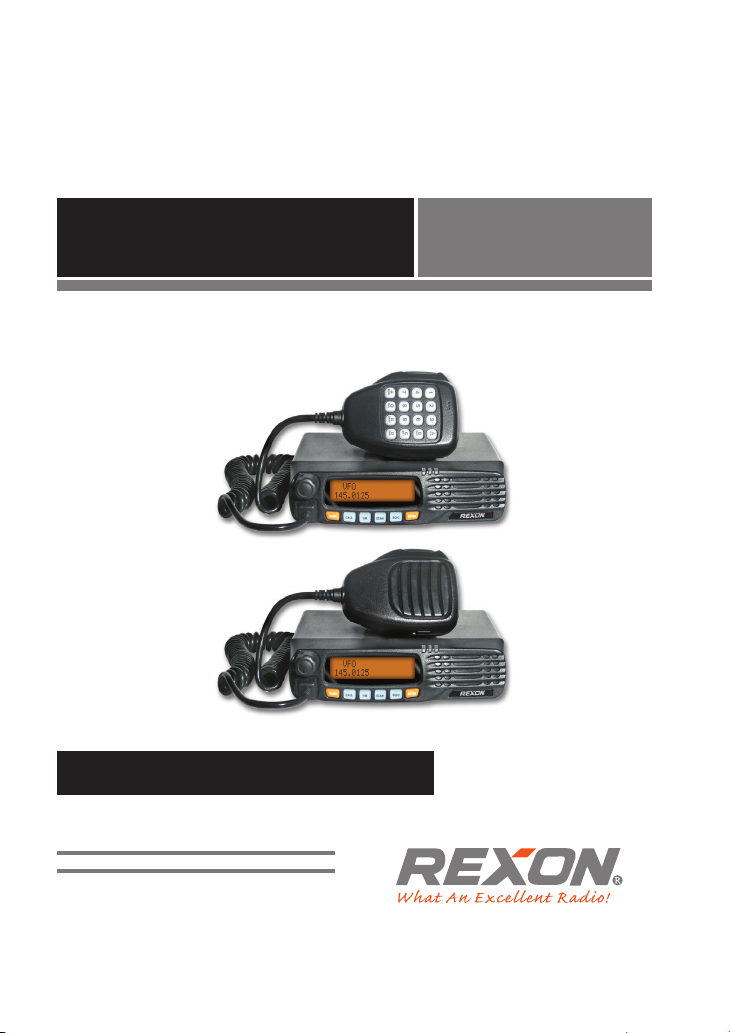
RM-03N
VHF/UHF TRANSCEIVER
INSTRUCTION MANUAL
Page 2

Table of Contents
Cautions ������������������������������������������������������������������1
Unpacking ���������������������������������������������������������������2
Installation & Connection ��������������������������������������3
Front Panel Description �����������������������������������������4
Rear Panel Description ������������������������������������������ 5
Operation Modes����������������������������������������������������6
Basic Operation ������������������������������������������������������7
• Turn The Radio On & O ������������������������������������������ 7
• Adjusting Volume ������������������������������������������������������ 7
• Change Operation Mode ���������������������������������������� 7
• Channel Selection / Frequency Changing �������� 7
• Lock The Buttons ��������������������������������������������������������7
• Scan ����������������������������������������������������������������������������� 8
• Monitor �������������������������������������������������������������������������� 8
• Transmitting ����������������������������������������������������������������� 9
• Receiving ����������������������������������������������������������������������� 9
Advanced Manual Operations �����������������������������10
• Editing A Channel ����������������������������������������������������10
• Duplicate A Channel ����������������������������������������������10
• Delete A Channel �����������������������������������������������������11
• Channel Name Tag ��������������������������������������������������11
• Make A Signalling Call ��������������������������������������������11
• Scan�������������������������������������������������������������������������������11
Page 3

• Priority Scan ���������������������������������������������������������������12
• TX Power Selection�������������������������������������������������12
• Oset ���������������������������������������������������������������������������13
• Band-Width Selection �����������������������������������������13
• Voice Compander ������������������������������������������������13
• Reverse TX/RX �����������������������������������������������������������13
• Searching & Dialing Pre-stored DTMF String �14
• Delete A Nuisance Channel ����������������������������������14
Menu for Radio’s General Setting �����������������������15
• Beep Enable/Disable �����������������������������������������������15
• TOT (Time-out timer) ���������������������������������������������15
• APO (Auto Power O) ��������������������������������������������16
• BCLO (Busy Channel Lockout) & BTLO ��������������16
• DTMF Transmitting Time ��������������������������������������17
• Squelch Level Setup �����������������������������������������������17
• Scan Dwell Time Setup ������������������������������������������18
• LCD Backlight ������������������������������������������������������������18
• Check Working Voltage �����������������������������������������18
• Burst Tone Selection �����������������������������������������������19
• DTMF ANI On/O �����������������������������������������������������19
• Channel Mode Setup ���������������������������������������������19
• Factory Default ��������������������������������������������������������20
Menu for Channel Settings ����������������������������������21
• Sub Tone (CTCSS/DCS) Encode Setup ������������21
• Sub Tone (CTCSS/DCS) Decode Setup �������������22
• DTMF/ 5 Tone/ 2 Tone Decode Selection ������22
Page 4

• Sending 2-Tone Call �����������������������������������������������23
• Sending 5-Tone Call �����������������������������������������������23
• Open Squelch Modes ���������������������������������������������24
• Oset Direction Setup ������������������������������������������24
• Oset Interval Setup �����������������������������������������������25
• Channel Step Setup �����������������������������������������������25
• Wide/Narrow Band Selection ���������������������������25
• Reverse TX/RX ����������������������������������������������������������26
• Talk Around ����������������������������������������������������������������26
• TX O Setup �����������������������������������������������������������26
• Compander ���������������������������������������������������������������27
• Scramble Setup(Optional) �����������������������������������27
MICROPHONE OPERATIONS ��������������������������������29
• Keypad Lock ��������������������������������������������������������������29
• Function Shortcut On Keypad �����������������������������29
• Restore Initial Setting ��������������������������������������������30
• Cloning ������������������������������������������������������������������������30
Page 5
Cautions
AVOID storing the radio under the sunshine or in hot areas� High tem-
perature can shorten the life of electronic devices, and warp or melt certain
plastics�
AVOID storing the radio in the dusty, dirty areas�
PLEASE keep the radio dry� Rainwater or damp will corrode electronic
circuits�
NEVER place the transceiver where normal operation of the vehicle may
be hindered or where it could cause bodily injury�
USE DC power supply, take notice of power voltage must be 13�8V only�
USE supplied microphone only� Other microphones have dierent pin
assignments and may damage the transceiver�
AVOID operating the transceiver without running the vehicle’s engine�
The vehicle’s battery will quickly run out if the transceiver is in transmission
while the vehicle’s engine OFF�
BE CAREFUL! The transceiver will overheat while operating con-
tinuously for a long period.
PAGE 1
Page 6
Unpacking
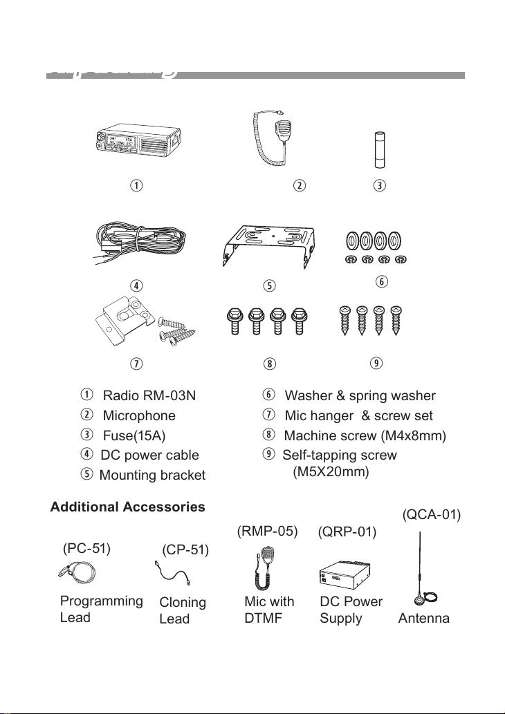
q w e
r
u i
Radio RM-03N
q
w Microphone
e Fuse(15A)
r DC power cable
t Mounting bracket
Additional Accessories
(PC-51)
Programming
Lead
(CP-51)
Cloning
Lead
t
y
o
y Washer & spring washer
u Mic hanger & screw set
i Machine screw (M4x8mm)
o Self-tapping screw
(M5X20mm)
(RMP-05)
Mic with
DTMF
(QRP-01)
DC Power
Supply
(QCA-01)
Antenna
PAGE 2
Page 7
Installation & Connection
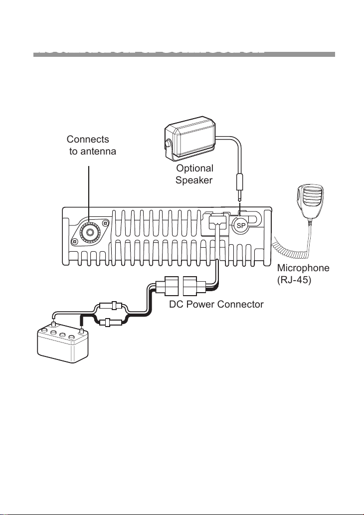
Connects
to antenna
Optional
Speaker
Microphone
(RJ-45)
RED(+)
12V Batter y
DC Power Connector
BLK(-)
PAGE 3
Page 8
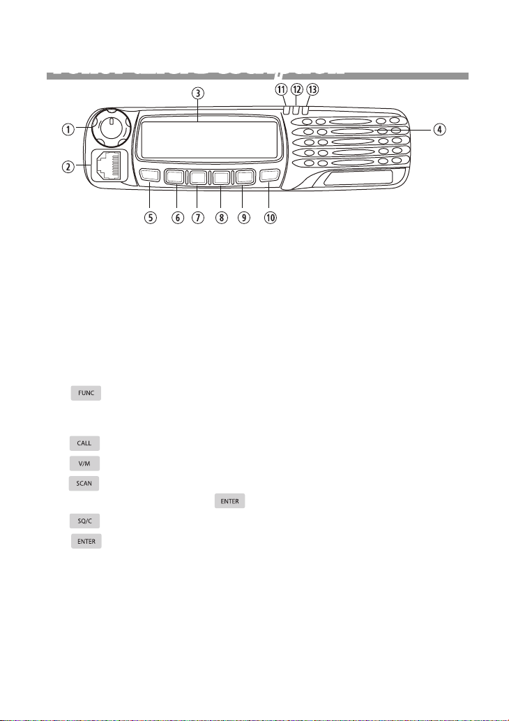
Front Panel Description
FUNC
C
A
L
L
V/M
SCAN
R
E
T
N
E
C
/
O
S
q Power button & Selector Knob:
Press the power button to turn radio ON, hold the button to turn radio OFF
for 3 seconds.
Turn selector knob clock wisely go through next channel or increase a frequency step and counter clock wisely to previous channel or decrease a frequency step.
w RJ45 Connector: Microphone connector or programming lead.
e LCD Display: The display include 16x2 two rows of dot matrix
r Speaker: Inner speaker
t button: Press it then press relevant key, or keep pressing within
2 seconds press relevant key to achieve multiple shortcut operations. Press
and hold more than 2 seconds to enter background operations.
y button: transmits selected DTMF/2-Tone/5Tone signalling
u button: To toggle channel and VFO mode.
i button: Select scan type FREQ/CH SCAN ,CTCSS/DCS SCAN or
PRIORITY WATCH then press button to execute.
o button: Press the button to temporarily monitor receiving.
a button: Press once to enter channel setup.
s Busy/Scan Indicator:
The lamp glows green when the channel is busy.
The lamp ashes green which mean matching carrier and signaling.
d TX indicator: The lamp glows red when the transceiver is transmitting.
f Power On Indicator: indicates transceiver is turn ON.
PAGE 4
Page 9
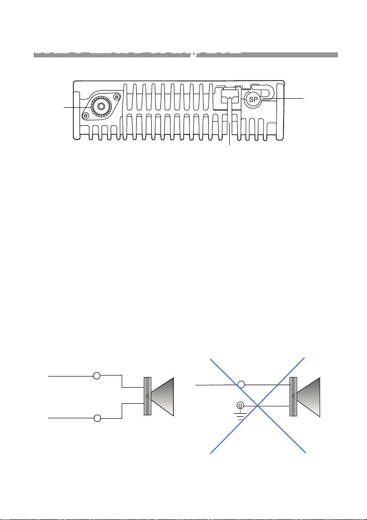
Rear Panel Description
q
e
q Antenna Socket
Connect an antenna to the socket with M type cable.
w
w DC Power Cable
Connects 12VDC battery to the cable. pay attention to polarities .
DO NOT connect to 24VDC battery. This will damage the transceiver.
e External Speak Jack :
Connects an 8 Ω external speaker with 3.5mm phone jack if desired.
CAUTION: External Speaker is designed with Bridge Tied
Load(BTL) audio output. The Speaker-plus and Speaker-minus
outputs should NEVER be tied to ground. Doing so could result in
damage to the BTL output , please following below installation.
Speaker +
Speaker
Speaker +
Speaker
Speaker -
Equipment Ground
PAGE 5
Page 10
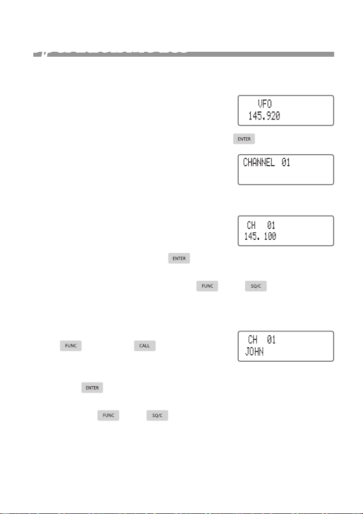
Operation Modes
There are four types of operation mode .
1. VFO mode (Frequency mode): This mode
shows only frequency on the display. All
menu settings will be changed & stored as
the latest value permanently, after pressing .
2. Channel number mode: At this mode, all
settings are done through PC programmer.
The user is not allowed to change any settings of the radio.
3. Channel+Frequency mode: At this mode,
frequency and channel number are shown
on LCD. The user can temporarily change
radio settings after pressing . Once the radio is turned off or
switched to another channel, the temporary setting will be erased
and back to initial settings. Press and to remove this
channel from scan list permanently. (Delete a nuisance channel
during scan.)
4. Channel+Name Tag mode: After press-
ing and then , you can rotate
the power knob to change name tag permanently. You can also temporarily change radio’s settings after
pressing . Once the radio is turned off or switched to another
channel, the temporary setting will be erased and back to initial settings. Press and buttons to remove this channel from
scan list permanently. (Delete a nuisance channel during scan.)
There are three levels of operation menu; shortcut operation
menu, channel setting menu and radio setting menu.
PAGE 6
Page 11

Basic Operation
• Turn The Radio On & Off
Press the power knob to turn the radio on. Hold power knob for 3
seconds to turn it off.
• Adjusting Volume
Press power knob once, LCD display will appear ”SET VOLUME”
, turn the knob clockwise to increase volume or counterclockwise to
reduce it.
• Change Operation Mode
Press on the front panel or on extended DTMF microphone
to toggle between either VFO mode (frequency) & Channel+Name
Tag mode, or VFO & Channel+Frequency mode.
Access is denied when the radio is programmed at Channel
mode
• Channel Selection / Frequency Changing
1. Channel mode: RM-03N can be programmed up to 250 channels.
Rotate power knob clockwise to go through next channel or counterclockwise to previous channel.
2. VFO mode: Rotate power knob to change the frequency. You can
also input the desired frequency through DTMF Mic. Channel step at
5KHz, 6.25KHz, 10KHz, 12.5KHz, 20KHz, 25KHz, 30KHz, or 50KHz
can be set by user after pressing
to choose it.
• Lock The Buttons
Press and then keep pressing for 2 seconds to lock all
buttons. Thus, radio’s settings would not be changed by user’s accidental touch.
PAGE 7
Page 12

• Scan
RM-03 allows optionally looking for carrier or carrier with CTCSS or
DCS. Your dealer can program those channels to be scanned on the
scan list.
Frequency/Channel Scan (Carrier Scan)
Press
then press
nels.
During scanning, press UP/DOWN button on the Mic or rotate power
knob to change scanning direction; press any button to stop scanning.
(except
When the transceiver is programmed with PA frequencies
and PB frequencies, in frequency mode (VFO), frequency subsection scan is valid. For more details, please refer to HELP options in
programming software.
CTCSS / DCS Scan (Tone Scan)
Press
SCAN?”. Then press
ing signaling, the scan will resume for 15 seconds. Press any key to
stop scanning.
Tone Scan will be invalid if no sub audio tone is received in
current channel. Press Mic UP/DOWN or power knob to change
scanning direction.
button repeatedly until LCD shows “FREQ/CH SCAN?”,
button to begin scanning per frequencies or per chan-
button).
button repeatedly till LCD displays “CTCSS/DCS
to start scanning. When nding a match-
• Monitor
This function allows you to override the squelch and the CTCSS
,DCS or 5 tone or listen to weak signal. Through PC programmer, you
can dene Monitor function to be operated as:
1. Keep pressing
monitor. or
2. Press
to stop monitor.
one time to activate monitor function. Presss it again
button to open squelch and release it to stop
PAGE 8
Page 13

• Transmitting
Before transmitting, it is recommended to monitor the channel you
are using to ensure it is not busy by pressing
button on extended microphone. Then, keep pressing PTT button
and start talking at approximately 2 inches from the Mic hole. During
transmitting, the LED on the front panel will glow red. Release PTT
button when you have nished talking.
button or Moni
Sending Burst Tone
Burst tone is an alternative means of accessing public repeater, except for sub audio tone such as CTCSS or DCS. Hold PTT button and
press DOWN key on the Mic, you will send out burst tone, which has
been set through PC programmer.
Sending Selcall Signalling
Hold PTT button and press UP key on the Mic, you will send out
DTMF/ 5 tone/ 2 tone signalling, which has been set through PC programmer.
• Receiving
RM-03N can be programmed to work channel by channel in “Open
trafc” or “Group Mode”(CTCSS or DCS). Group mode prevents other
users on the same channel from being heard on your radio.
Open Trafc:
In this mode, you will hear all communication transmitted on the
channel. When a message is received, radio’s squelch will be unmute and LED will grow green, and you will hear the message.
Group Mode:
CTCSS/DCS (Continuous Tone Code Squelch system / Digital Coded Squelch) are particular TX signaling as an access key to work a
repeater (encoder) or to unlock the party signaling sensitive squelch.
In group mode,
PAGE 9
Page 14
You will receive only messages coming from those parties sending
a proper TX signaling. (By this way, more radios share the same frequency.) If an incorrect code or no code is received, LED glow green
but squelch will still remain mute.
Advanced Manual Operations
• Editing A Channel
1. In VFO mode, turn power knob to select the frequency you need.
2. Press button to edit all settings in channel mode.(Please refer
channel mode settings)
3. Press button, LCD will show “FUNC”. Then, press but-
ton, and LCD will appear “WAIT”.
4. Rotate power knob to choose a channel would be stored with the
above setting.
5. Press button, LCD will show “FUNC”. Then hold button
for 2 seconds till LCD appears “COPY”. Finally the radio sounds
2 beeps, “COPY” is disappeared and the channel editing is stored
successfully.
• Duplicate A Channel
1. In VFO mode, press button to get into channel mode. Then
rotate power knob to select the source channel.
2. Press button, LCD will show “FUNC”. Then, press but-
ton LCD will appear “WAIT”
3. Rotate power knob to select the destination channel.
4. Press button, LCD will appear “FUNC”. Hold button for
2 seconds till LCD shows “COPY”. Finally the radio sound 2 beeps,
PAGE 10
Page 15
“COPY” is disappeared and the channel duplicating is stored successfully.
• Delete A Channel
1. In VFO mode or channel mode, press button, LCD will show
“FUNC”. Then, press button, LCD will appear “WAIT”.
2. Rotate power knob to select a channel being deleted.
3. Press button, LCD will show “FUNC”. Hold button for 2
seconds till LCD appears “CLEAR”. Finally the radio sound 2 beep,
“CLEAR” is disappeared and channel is deleted successfully.
4. Repeat step 2 & 3 to delete more channels continuously.)
5. Press button to exit
• Channel Name Tag
In channel name tag mode, press button and then press
button to edit its channel name tag. Rotate power knob to set alphanumeric you want. Press
button for next character. Finally press
exit.
button for previous character or
button to conrm and
• Make A Signalling Call
Press button to make a signalling call, if this channel has bee
programmed with signalling (DTMF, 2-Tone, 5-Tone) by your dealer. .
• Scan
Frequency/Channel Scan (Carrier Scan)
Press
then press
nels.
During scanning, press UP/DOWN button on the Mic or rotate power
button repeatedly until LCD shows “FREQ/CH SCAN?”,
button to begin scanning per frequencies or per chan-
PAGE 11
Page 16

knob to change scanning direction; press any button to stop scanning.
(except
button).
When the transceiver is programmed with PA frequencies
and PB frequencies, in frequency mode (VFO), frequency subsection scan is valid. For more details, please refer to HELP options in
programming software.
CTCSS / DCS Scan (Tone Scan)
Press
SCAN?”. Then press
ing signaling, the scan will resume for 15 seconds. Press any key to
stop scanning.
button repeatedly till LCD displays “CTCSS/DCS
to start scanning. When nding a match-
Tone Scan will be invalid if no sub audio tone is received
in current channel. Press Mic UP/DOWN or rotate power knob to
change scanning direction
• Priority Scan
In VFO mode, Priority scan will monitor the priority scan channel
once every 5 seconds.
1. In VFO mode, press button switch to channel mode. Then,
rotate power knob to select a channel as priority channel.
2. Press button repeatedly till LCD displays “PRIORITY
WATCH?”, then press button to start priority scanning.
When the priority channel receives a matching carrier and
signaling, scanning will resume at priority scan channel for 10 seconds. If you press PTT during this time, the priority scan will be
stopped and the radio will stay in this channel for communication.
• TX Power Selection
Keep pressing and then buttons or press H/L button at
extended Mic repeatedly to choose TX power among HIGH/MIDDLE/
LOW.
1. “TX POWER HIGH” indicates TX power is high.
PAGE 12
Page 17

2. “TX POWER MIDDLE” indicates Tx power is middle.
3. “TX POWER LOW” indicates TX power is low.
In Channel number mode, the user is not allowed to change
TX power manually.
• Offset
Keep pressing and then buttons to choose either OFFSET+/OFFSET-/ OFFSET OFF.
1. “OFFSET+” indicates plus offset Transmitting frequency is higher
than receiving frequency.
2. “OFFSET-” indicates minus offset Transmitting frequency is lower
than receiving frequency.
3. “OFFSET OFF” indicates shut offset off.
• Band-Width Selection
Keep pressing and then buttons to choose bandwidth
among 25K/20K/12.5K.
1. “W/N 25K” indicates wide band.
2. “W/N 20K” indicates middle band.
3.“W/N 12.5K” indicates narrow band.
In Channel number mode, the user is not allowed to change
band width manually.
• Voice Compander
Keep pressing and then buttons to switch COMPANDER
ON or OFF.
“COMPANDER ON” : Compander feature is activated.
“COMPANDER OFF”: Compander feature is not activated.
• Reverse TX/RX
Keep pressing and then buttons to switch REVERSE ON
or OFF.
PAGE 13
Page 18

“REVERSE ON” : TX & RX will be reversed.
“REVERSE OFF”: TX & RX will remain as it is programmed.
• Searching & Dialing Pre-stored DTMF String
RM-03N can be programmed with 16 pre-stored DTMF string dial.
(Pre-stored DTMF string dials must be edited through PC programmer)
1. Press button once, and then press button to get into
pre-stored DTMF dial list. “EMPTY” means there are nothing in
pre-stored code.
2. Rotate power knob or press UP/DOWN on the Mic to choose DTMF
string dial.
3. Press PTT or button to send DTMF string dial.
In Channel number mode, the user is not allowed to choose
DTMF dial manually.
• Delete A Nuisance Channel
lt allows you to remove the channels which you don’t want to hear
from the scan list. Press
switch SKIP ON/OFF.
1. “SKIP ON” indicates current channel will be deleted from scan list.
button once and press button to
2. “SKIP OFF” indicates current channel will be remaining the scan
list.
This operation is only available in channel + name mode &
channel + frequency modes. It is invalid in channel number mode &
VFO mode.
PAGE 14
Page 19
Menu for Radio’s General Setting
Any changing on the general settings will be stored permanently.
These general settings can be done through buttons in any mode
(VFO/Channel):
3. Keep pressing
of RM-03N.
4. Press button repeatedly or press Up/Down key on extended
microphone till desired setting appears.
5. Rotate power knob to change the setting.
6. Press button conrm and exit.
for 2 seconds to get into general setting menu
• Beep Enable/Disable
The beep sound indicates conrmation of entry, error status, and
malfunctions.
1. Hold button for 2 seconds to get into general setting menu.
2. Press button repeatedly or press Up/Down key on extended
microphone till LCD displays “BEEP”
3. Rotate power knob to select ON or OFF.
4. ON: Beep enabled ; OFF: Beep disabled
Default: ON
• TOT (Time-out timer)
TOT is the function that prevents from locking up a repeater or frequency by prolonged keying of PTT. The time-out timer limits the
amount of time you have to transmit your message. When you reach
the time limit which has been programmed by your dealer, your transmission will be cut off. In order to transmit again, you must push PTT
button to reset the timer.
PAGE 15
Page 20

1. Hold button for 2 seconds to get into general setting menu.
2. Press button repeatedly or press Up/Down key on extended
microphone till LCD displays “TIME OUT TIMER”
3. Rotate power knob to select OFF/1~30Min
4. OFF: Time-out timer disabled
Default: OFF
• APO (Auto Power Off)
Once APO is activated, the radio will be automatically switched off
when the pre-set timer is running to end.
1. Hold button for 2 seconds to get into general setting menu.
2. Press button repeatedly or press Up/Down key on extended
microphone till LCD displays “AUTO POWER OFF”
3. Rotate power knob to select OFF/1 /2 HOUR.
4. 30MIN: Automatic power off after 30 minutes; 1HOUR:Automatic
power off after 1 hour; 2HOUR Automatic power off after 2 hours
Default: OFF
• BCLO (Busy Channel Lockout) & BTLO
BCLO is to disable transmitting while RX signal is received. Once
the channel is busy and you press PTT, the radio will beep as warning
and get back to receiving.
BTLO is mainly for repeater application. It will not be transmitted
until receiving RX carrier with correct sub tone. If the repeater is occupied by other group when you press PTT button, BTLO will standby
till the using group is leaving. And then, the radio’s loudspeaker will
beep for 3 times to remind you that you are allowed to use the repeater
now.
1. Hold button for 2 seconds to get into general setting menu.
2. Press button repeatedly or press Up/Down key on extended
PAGE 16
Page 21

microphone till LCD displays “LOCKOUT”
3. Rotate power knob to set OFF/BUSY/REPEATER LOCK.
4. REPEATER LOCK: transmitting is inhibited when current channel
receives a matching carrier but dis-matching CTCSS/DCS.
5. BUSY: Carrier lockout, transmitting is inhibited when current chan-
nel receives a matching carrier;
6. OFF: Busy channel lockout is disabled.
Default: OFF
• DTMF Transmitting Time
1. Hold button for 2 seconds to get into general setting menu.
2. Press button repeatedly or press Up/Down key on extended
microphone till LCD displays “DTMF SPEED”
3. Rotate power knob to set 50MS/100MS/200MS/300MS/500MS,
which indicates the time for sending each DTMF signal & the interval between each DTMF being sent.
Default: 100MS
• Squelch Level Setup
Setting the radio to a tight squelch level, you can avoid unwanted
signals or noise, but you may not receive a weak signal. Therefore, it
will be better for you to select the normal squelch level (default value:
4).
1. Hold button for 2 seconds to get into general setting menu.
2. Press button repeatedly or press Up/Down key on extended
microphone till LCD displays “SQUEL LEVEL”
3. Rotate power knob to set squelch level between off-20. off means
open squelch and speaker.
PAGE 17
Page 22

quick tips : You can also adjust the squelch level by keep
pressing button, and then rotating power knob.
• Scan Dwell Time Setup
1. Hold button for 2 seconds to get into general setting menu.
2. Press button repeatedly or press Up/Down key on extended
microphone till LCD displays “DWELL TIME”
3. Rotate power knob to set PAUSE/5/10/15 Sec.
4. 5SEC/10SEC/15SEC means the scan resume time. Once the ra-
dio stops on a busy channel, Scan mode will stop and resume for
a period of time.
5. Pause: Once the radio stops on a busy channel, Scan will not keep
going until RX signal is gone for 2 seconds.
Default: 15SEC
This setup can be also applied to CTCSS/DCS scan
• LCD Backlight
1. Hold button for 2 seconds to get into general setting menu.
2. Press button repeatedly or press Up/Down key on extended
microphone till LCD displays “BACKLIGHT”
3. Rotate power knob to select LOW/HIGH.
4. LOW:. Low brightness; HIGH:. High brightness
Default: HIGH
• Check Working Voltage
1. Hold button for 2 seconds to get into general setting menu.
2. Press button repeatedly or press Up/Down key on extended
microphone till LCD displays “VOLTAGE”
PAGE 18
Page 23

3. The LCD will show working voltage.
• Burst Tone Selection
Burst tone is an alternative means of accessing the repeater, in addition to CTS or DCS tone.
1. Hold button for 2 seconds to get into general setting menu.
2. Press button repeatedly or press Up/Down key on extended
microphone till LCD displays “TBST”
3. Rotate power knob to set burst tone at either 1750Hz, 2100Hz,
1000Hz, or 1450Hz.
Default: 1750Hz
• DTMF ANI On/Off
Alpha Numeric Identication function is available by DTMF or 5Tone
signaling. Enable this function, the radio will display the caller’s ID
number when receiving a DTMF ANI calling
1. Hold button for 2 seconds to get into general setting menu.
2. Press button repeatedly or press Up/Down key on extended
microphone till LCD displays “DTMF ANI”
3. Rotate power knob to switch ON/OFF.
4. OFF: DTMF ANI is disable; ON: DTMF ANI is enabled.
Default: OFF
Notice: DTMF or 5 tone ANI must be set through PC pro-
grammer.
• Channel Mode Setup
There are 3 different Channel modes: Channel+frequency mode,
Channel+name tag mode, & Channel mode.
1. Hold button for 2 seconds to get into general setting menu.
2. Press button repeatedly or press Up/Down key on extended
PAGE 19
Page 24

microphone till LCD displays “DISPLAY TYPE”
3. Rotate power knob to choose either FREQ/CHANNEL/NAME.
Default: FREQ
Once you choose Channel mode, the radio will not be able to
switch between channel & VFO modes by pressing
button.
• Factory Default
If your radio seems to be malfunctioning, resetting the microprocessor may solve the problem. When performing the reset, you may lose
memory data and stored information. Back up or write down important data before performing the reset.
1. Hold button for 2 seconds to enter menu items.
2. Press button repeatedly or press Up/Down key on extended
microphone until LCD shows “RESTORE”
3. Turn selector knob to choose OFF/SETUP?/FACTORY.
4. FACTORY: resume factory default; SETUP: return initial setup;
OFF:Non application
5. Press button to conrm and exit.
PAGE 20
Page 25
Menu for Channel Settings
In channel modes, including channel + frequency mode & channel
+ name tag mode, the edition of channel menu setting is a temporary
changing. Once you turn the radio off or switch to other channel, this
temporary setting will be erased and back to initial channel setting by
PC programmer.
1. Under Channel modes, press button to get into channel
menu.
2. Press the button repeatedly or press Up/Down key on ex-
tended microphone to turn through the channel menu.
3. Rotate power knob to set parameter.
4. Press or button to conrm and exit the channel menu
setup.
This edition is invalid in channel number mode. The edition
of channel setting in VFO mode will be stored permanently.
• Sub Tone (CTCSS/DCS) Encode Setup
1. Press button to get into channel menu.
2. Press button repeatedly or press Up/Down key on extended
microphone till LCD shows “CTDCS/ ENCODE”
3. Press button to select CTCSS, DCS or OFF. When DCS is
selected, press button to select N or I (positive /inverse)
4. Rotate power knob to select CTCSS/DCS subtone.
5. CTCSS code: 62.5Hz-254.1Hz, total 51 subtones.
6. DCS code: 000N-777I, total 1024 codes, N stands for positive code,
I stands for inverse code.
Default : 023N
PAGE 21
Page 26

• Sub Tone (CTCSS/DCS) Decode Setup
1. Press button to get into channel menu.
2. Press button repeatedly or press Up/Down key on extended
microphone till LCD shows “CTDCS DECODE”
3. Press button to select CTCSS, DCS, or OFF. When DCS is
selected, press button to select N or I (positive /inverse)
4. Rotate power knob to select CTCSS/DCS subtone.
5. CTCSS code: 62.5Hz-254.1Hz, total 51 subtones.
6. DCS code: 000N-777I, total 1024 codes, N stands for positive code,
I stands for inverse code.
Default: 023N
• DTMF/ 5 Tone/ 2 Tone Decode Selection
DTMF/ 5Tone/ 2Tone signalling function as similarly as CTCSS/
DCS. Without receiving correspondent tone signalling, the speaker
will remain mute. DTMF and 5Tone signalling can be applied for other
advanced features such as ANI, PTT ID, group call, individual call,
stun, remote kill, revival, tail eliminator,...etc. The signalling edition
must be done through PC programmer. Please refer to the HELP
option in the programming software to know how to operate these
features.
1. Press button to get into channel menu.
2. Press button repeatedly or press Up/Down key on extended
microphone till LCD shows “TONE DECODE”
3. Rotate power knob to select either DTMF/ 2TONE/ 5TONE/ OFF.
4. “DTMF”: the channel will be mute by a DTMF signal. The speaker
won’t be open until receiving a correspondent DTMF signal. To
transmit the pre-stored DTMF signaling, hold “PTT” then press UP.
5. “2TONE: the channel will be mute by a 2-Tone signal. The speaker
PAGE 22
Page 27

won’t be open until receiving a correspondent 2-Tone signal. To
transmit the pre-stored 2-Tone signaling, hold “PTT” then press
UP.
6. “5Tone”: the channel will be mute by a 5-Tone signal. The speaker
won’t be open until receiving a correspondent 5-Tone signal. To
transmit the pre-stored 5-Tone signaling, hold “PTT” then press
UP.
7. “OFF”: DTMF, 2Tone, or 5Tone signaling decoder is cancelled and
this channel will not be mute.
• Sending 2-Tone Call
1. Press button to get into channel menu.
2. Press button repeatedly or press Up/Down key on extend-
ed microphone till LCD shows “2TONE CALLXX” , XX means the
group in the list.
3. Rotate power knob to select the 2-Tone group you want to send.
Press PTT to transmit the selected 2Tone group call.
There are up to 32 groups of 2-Tone Call to be set with name
alias through PC programmer.
• Sending 5-Tone Call
1. Press button to get into channel menu.
2. Press button repeatedly or press Up/Down key on extend-
ed microphone till LCD shows “5TONE CALLXX” , XX means the
group in the list.
3. Rotate power knob to select the 5-Tone group you want to send.
Press PTT to transmit the selected 5-Tone group call.
There are up to 100 groups of 5-Tone Call to be set with
name alias through PC programmer.
PAGE 23
Page 28

• Open Squelch Modes
This function used to setup the mode to open radio’s squelch.
1. Press button to get into channel menu.
2. Press button repeatedly or press Up/Down key on extended
microphone till LCD shows “SIGNAL”
3. Rotate power knob to select either SQUELCH, CTCSS/DCS,
CTDCS&TONE, or CTDCS/TONE .
“SQUELCH”: The speaker will be unmute while receiving a matching carrier.
“CTCSS/DCS”, The speaker will be unmute while receiving a matching carrier and CTCSS/DCS sub audio tone.
“TONE”, The speaker will be unmute while receiving a matching
carrier and DTMF/2-Tone/5-Tone signaling.
“CTDCS&TONE”, The speaker will be unmute while receiving
a matching carrier and CTCSS/DCS sub audio tone and DTMF/2Tone/5-Tone signaling.
“CTDCS/TONE”, The speaker will be unmute while receiving a
matching carrier and either CTCSS/DCS/DTMF/2-Tone/5-Tone signaling.
• Offset Direction Setup
This function should coordinate with the offset frequency setup,
which enable you to communication with other transceivers through
a repeater.
1. Press button to get into channel menu.
2. Press button repeatedly or press Up/Down key on extended
microphone till LCD shows “OFFSET”
3. Rotate power knob to select an offset direction
4. “OFFSET-”, indicate minus offset, TX frequency is lower than RX
frequency. When “Reverse” function is enabled, TX frequency will
be higher than RX frequency.
PAGE 24
Page 29

5. “OFFSET+”, indicate plus offset, TX frequency is higher than RX
frequency. When “Reverse” function is enabled, TX frequency will
be lower than RX frequency.
6. “OFFSET OFF” means shut offset function off.
Note: Offset function will be invalid when “Talk around”
function is enabled.
• Offset Interval Setup
1. Press button to get into channel menu.
2. Press button repeatedly or press Up/Down key on extended
microphone till LCD shows “OFFSET FREQ”
3. Rotate power knob to set offset frequency from 00 to 69.995 MHz.
4. default is 0.6MHz.
• Channel Step Setup
Channel step means the frequency interval to the next frequency.
1. Press button to go through channel menu settings.
2. Press button repeatedly or press Up/Down key on extended
microphone till LCD shows “STEP”
3. Rotate power knob to select a channel step from 5K, 6.25K, 10K,
12.5K, 20K, 25K, 30K,or, 50K.. Default: 20K
This function work in frequency (VFO) mode only.
• Wide/Narrow Band Selection
Select band width.
1. Press button to get into channel menu.
2. Press button repeatedly or press Up/Down key on extended
microphone till LCD shows “W/N”
3. Rotate power knob to select bandwidth from 25KHz, 20KHz, or
PAGE 25
Page 30

12.5KHz.
• Reverse TX/RX
TX frequency turns to RX frequency & RX frequency change to TX
frequency. The signaling will also be reversed if CTCSS/DCS signaling existed in this channel.
1. Press button to get into channel menu.
2. Press button repeatedly or press Up/Down key on extended
microphone till LCD shows “REVERSE”
3. Rotate power knob to set ON/OFF reverse frequency.
4. ON: enable frequency reverse; OFF: disable frequency reverse
This function will be disabled while “Talk around” function
is enabled.
• Talk Around
By Talk Around function, you can directly communicate with other
radios in your group in case the repeater is not activated or when you
are out of the repeater range. The transceiver will transmit by RX
frequency with its CTCSS/DCS signaling.
1. Press button to get into channel menu.
2. Press button repeatedly or press Up/Down key on extended
microphone till LCD shows “Talk Around”.
3. Rotate power knob to switch ON or OFF.
4. ON: talk around enabled; OFF: talk around disabled.
Default: OFF
• TX Off Setup
PTT is invalid and the current channel works in RX mode.
1. Press button to get into channel menu.
2. Press button repeatedly or press Up/Down key on extended
PAGE 26
Page 31

microphone till LCD shows “TX INHIBIT”.
3. Rotate power knob to switch ON or OFF.
4. ON: TX OFF function is enabled, PTT is invalid.
5. OFF: TX OFF function is disabled, PTT is valid.
Default: OFF
• Compander
Enable this function to reduce background noise and enhance audio clarity, especially in long range communication.
1. Press button to get into channel menu.
2. Press button repeatedly or press Up/Down key on extended
microphone till LCD shows “COMPANDER”.
3. Rotate power knob to switch ON or OFF.
4. ON: voice compander is enabled; OFF: compander is disabled
Default: OFF
• Scramble Setup(Optional)
An analog voice inversion scrambler can be equipped as optionals.
This special audio process can offer a more condential communication. Other radios at same frequency will receive only disordered
PAGE 27
Page 32

noises.
1. Press button to get into channel menu.
2. Press button repeatedly or press Up/Down key on extended
microphone till LCD shows “SCRAMBLE”.
3. Rotate power knob to switch ON or OFF.
4. ON: Scrambler is enabled; OFF: Scrambler is disabled
Default: OFF
PAGE 28
Page 33
MICROPHONE OPERATIONS
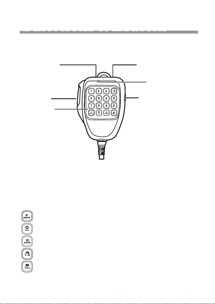
Using convenient microphone keypad to operate desired frequency/
channel through the RMP-05 Mic keys
Down Key
PTT key
Keypad
Up Key
Microphone
Keypad lock
• Keypad Lock
Pull down the slider switch to lock keypad for overriding keypad entry, The lamp is turned off and all of keypads is not work except PTT
switch.
• Function Shortcut On Keypad
Moni button : forced monitor this channel or frequency.
Power button: switch tx power to HI/MIDDLE/LOW level.
Bandwidth button: switch bandwidth to 12.5K/20K/25KHz.
V/M button : Toggle VFO to frequency with channel mode
button : Transmit selected signaling (DTMF,2-Tone,5-Tone)
PAGE 29
Page 34
button: Set function menu list same as channel operation,
Press button repeatedly or press Up/Down key on extended microphone. Then press button to conrm and exit.
work failure at channel number mode.
button : Transmit string dial , press Down/Up key to select prestored DTMF codes, data entry through the number keys as well , then
press PTT to transmit and store the data.
Numbers button: Frequency entry or channel selection by extended
microphone.
• Restore Initial Setting
Holding and buttons turn the radio on to start initializa-
tion.
All programming data will be automatically delete after this
operation.
• Cloning
Duplicate a radio by cloning lead.
1. Plug cloning lead into source and destination radio.
2. Holding and buttons and then turn the radio on, LCD
shows “CLONE”.
3. Press button on source radio, both of radios show “CLONE
xx”, xx means cloned size.
4. Destination radio will restart after nished cloning. unplug the desti-
nation radio and plug a new radio which desired cloning. follow step
2 and 4 for more radios. turn off the source radio after all done.
PAGE 30
 Loading...