


®
M2507R
10 in. (254 mm) MiterMate
TM
COMPOUND MITER SAW
INSTRUCTION MANUAL

2 3
SECTION PAGE
Product Specifications .............................................................................
2
Power Tool Safety ....................................................................................
3
Compound Miter Saw Safety ................................................................... 5
Electrical Requirements and Safety...........................................................
7
Tools Needed for Assembly ..................................................................... 8
Carton Contents ....................................................................................... 9
Know Your Miter Saw.................................................................................
10
Assembly ................................................................................................. 11
Adjustments ............................................................................................. 15
Operation ................................................................................................. 21
Maintenance ............................................................................................ 33
Troubleshooting Guide ............................................................................ 34
Parts List ................................................................................................ 35
MOTOR
Power Source ..................................................................... 220V~ 50Hz
Speed ................................................................................. 4800 min-1 (No load)
Brake .................................................................................. Electric
Double Insulated ................................................................. Yes
BLADE SIZE
Diameter.............................................................................. 254 mm
Arbor size............................................................................ 25.4 mm w/a 16 mm
reducer
ROTATING TABLE
Diameter.............................................................................. 32.4 mm
Miter Detent Stops .............................................................. 0°, 22.5°, 45° R & L
Bevel Positive Stops ........................................................... 0, 45° L
CUTTING CAPACITY
Crosscut .............................................................................. 66.7 mm x 141.3 mm
Miter 45° R & L .................................................................... 66.7 mm x 88.9 mm
Bevel 45° L .......................................................................... 39.7 mm x 141.3 mm
45° Miter and 45° Bevel ....................................................... 39.7 mm x 88.9 mm
Crown Molding Nested Against Fence................................. 108 mm
TABLE OF CONTENTS
PRODUCT SPECIFICATIONS

GENERAL SAFETY INSTRUCTIONS
BEFORE USING THIS POWER TOOL
Safety is a combination of common
sense, staying alert and knowing how
to use your power tool.
CAUTION
To avoid mistakes that could cause
serious injury, do not plug the tool in
until you have read and understood
the following.
1. READ and become familiar with
the entire Instruction
Manual. LEARN the tool’s
application, limitations and
possible hazards.
2. KEEP GUARDS IN PLACE and in
working order.
3. REMOVE ADJUSTING KEYS
AND WRENCHES. Form the habit
of checking to see that keys and
adjusting wrenches are removed
from the tool before turning ON.
4. KEEP WORK AREA CLEAN.
Cluttered areas and benches invite
accidents.
5. DO NOT USE IN DANGEROUS
ENVIRONMENTS. Do not use
power tools in damp locations, or
expose them to rain or snow. Keep
work area well lit.
6. KEEP CHILDREN AWAY. All
visitors and bystanders should be
kept a safe distance from work
area.
7. MAKE WORKSHOP CHILD
PROOF with padlocks, master
switches or by removing starter
keys.
8. DO NOT FORCE THE TOOL. It will
do the job better and safer at the
rate for which it was designed.
9. USE THE RIGHT TOOL. Do not
force the tool or an attachment
to do a job for which it was not
designed.
10. USE PROPER EXTENSION
CORDS. Make sure your extension
cord is in good condition. When
using an extension cord, be sure
to use one heavy enough to carry
the current your product will draw.
An undersized cord will result in a
drop in line voltage and in loss of
power which will cause the tool to
overheat.
11. WEAR PROPER APPAREL. Do
not wear loose clothing, gloves,
neckties, rings, bracelets or other
jewelry which may get caught in
moving parts. Nonslip footwear is
recommended. Wear protective
hair covering to contain long hair.
12. ALWAYS WEAR EYE
PROTECTION. Any power
tool can throw foreign
objects into the eyes and
could cause permanent eye
damage. ALWAYS wear Safety
Goggles (not glasses) that comply
with ANSI Safety standard Z87.1.
Everyday eyeglasses have
only impact–resistant lenses.
They ARE NOT safety glasses.
NOTE: Glasses or goggles not in
compliance with ANSI Z87.1 could
seriously injure you when they
break.
POWER TOOL SAFETY

4 5
20. NEVER LEAVE THE TOOL
RUNNING UNATTENDED. TURN
THE POWER “OFF”. Do not walk
away from a running tool until the
blade comes to a complete stop
and the tool is unplugged from the
power source.
21. DO NOT OVERREACH. Keep
proper footing and balance at all
times.
22. MAINTAIN TOOLS WITH CARE.
Keep tools sharp and clean for best
and safest performance. Follow
instructions for lubricating and
changing accessories.
23. DO NOT use power tool in
presence of flammable liquids or
gases.
24. DO NOT operate the tool if you are
under the influence of any drugs,
alcohol or medicationn that could
affect your ability to use the tool
properly.
25. WARNING: Dust generated from
certain materials can be hazardous
to your health. Always operate saw
in well-ventilated area and provide
for proper dust removal.
26.
People with
electronic devices,
such as pacemakers, should
consult their physician(s) before
using this product. Operation
of electrical equipment in close
proximity to a heart pacemaker
could cause interference or failure
of the pacemaker.
27. WEAR HEARING
PROTECTION to reduce
the risk of induced hearing
loss.
13. WEAR A FACE MASK
OR DUST MASK. Sawing
operation produces dust.
14. SECURE WORK. Use clamps or
a vise to hold work when
practical. It is safer than
using your hand and it frees
both hands to operate the
tool.
15. DISCONNECT TOOLS FROM
POWER SOURCE before servicing,
and when changing accessories
such as blades, bits and cutters.
16. REDUCE THE RISK OF
UNINTENTIONAL STARTING.
Make sure switch is in the OFF
position before plugging the tool in.
17. USE RECOMMENDED
ACCESSORIES. Consult this
Instruction Manual for recommended
accessories. The use of improper
accessories may cause risk of injury
to yourself or others.
18. NEVER STAND ON THE TOOL.
Serious injury could occur if the
tool is tipped or if the cutting tool is
unintentionally contacted.
19. CHECK FOR DAMAGED PARTS.
Before further use of the tool, a
guard or other part that is damaged
should be carefully checked to
determine that it will operate
properly and perform its intended
function – check for alignment of
moving parts, binding of moving
parts, breakage of parts, mounting
and any other conditions that may
affect its operation. A guard or
other part that is damaged should
be properly repaired or replaced.
DANGER
!

COMPOUND MITER SAW SAFETY
SPECIFIC SAFETY INSTRUCTIONS
FOR THIS COMPOUND MITER SAW
1. DO NOT USE THIN KERF
BLADES they can deflect and
contact guard and can cause
possible injury to the operator.
2. DO NOT operate the miter saw
until it is completely assembled
and installed according to these
instructions.
3. IF YOU ARE NOT thoroughly
familiar with the operation of miter
saws, seek guidance from your
supervisor, instructor or other
qualified person.
4. ALWAYS hold the work firmly
against the fence and table.
DO NOT perform any operation
free hand (use clamp wherever
possible).
5. KEEP HANDS out of the path of the
saw blade. If the workpiece you are
cutting would cause your hands to
be within 15.2 cm. of the saw blade,
the workpiece should be clamped in
place before making the cut.
6. BE SURE the blade is sharp, runs
freely and is free of vibration.
7. ALLOW the motor to come up to
full speed before starting a cut.
8. KEEP THE MOTOR AIR SLOTS
CLEAN and free of chips or dust.
9. ALWAYS MAKE SURE all handles
are tight before cutting, even if the
table is positioned in one of the
positive stops.
10. BE SURE both the blade and the
collar are clean and the arbor bolt
is tightened securely.
11. USE only blade collars specified for
your saw.
12. NEVER use blades larger in
diameter than 254 mm.
13. NEVER apply lubricants to the
blade when it is running.
14. ALWAYS check the blade for
cracks or damage before operation.
Replace a cracked or damaged
blade immediately.
15. NEVER use blades recommended
for operation at less than 4800
RPM.
16. ALWAYS keep the blade guards in
place and use at all times.
17. NEVER reach around the saw
blade.
18. MAKE SURE the blade is not
contacting the workpiece before the
switch is turned ON.
19. IMPORTANT: After completing the
cut, release the trigger and wait for
the blade to stop before returning
the saw to the raised position.
20. MAKE SURE the blade has come
to a complete stop before removing
or securing the workpiece,
changing the workpiece angle or
changing the angle of the blade.
21. NEVER cut metals or masonry
products with this tool. This miter
saw is designed for use on wood
and wood-like products.

6 7
22. NEVER cut small pieces. If the
workpiece being cut would cause
your hand or fingers to be within
15.2 cm. of the saw blade the
workpiece is too small.
23. PROVIDE adequate support to the
sides of the saw table for long work
pieces.
24. NEVER use the miter saw in an
area with flammable liquids or
gases.
25. NEVER use solvents to clean
plastic parts. Solvents could
possibly dissolve or otherwise
damage the material.
26. SHUT OFF the power before
servicing or adjusting the tool.
27. DISCONNECT the saw from
the power source and clean the
machine when finished using.
28. MAKE SURE the work area is
clean before leaving the machine.
29. SHOULD any part of your miter saw
be missing, damaged, or fail in any
way, or any electrical component
fail to perform properly, lock the
switch and remove the plug from
the power supply outlet. Replace
missing, damaged, or failed parts
before resuming operation.

CONNECTING TO THE POWER SUPPLY
Check that the power supply and plug used is in accordance with your miter saw.
Have a look at the rating plate of the motor or the rating on the miter saw. Any
changes should always be carried out by a qualified electrician.
This machine must be earthed.
If not properly earthed this machine can cause an electrical shock. Be sure that
the power supply outlet is earthed. If there is any doubt, have it checked by a
qualified electrician.
Avoid contact with the terminals on the plug when installing (removing) the
plug to (from) the power supply outlet. Contact will cause a severe electrical
shock.
USING AN EXTENSION LEAD
The use of any extension lead will cause some loss of power. To keep this to
a minimum and to prevent overheating and motor burn-out, ask advice from a
qualified electrician to determine the minimum wire size of the extension lead.
The extension lead should be equipped with an earthed type plug that fits the
power supply outlet at one end, and with an earthed type socket that fits the plug
of this machine at the other end.
WARNING
!
WARNING
!
ELECTRICAL REQUIREMENTS AND SAFETY

8 9
Blade Wrench
Supplied Not supplied
TOOLS NEEDED FOR ASSEMBLY
Phillips Screwdriver
Adjustable Wrench
Hex Wrench
Combination Square
Slotted Screwdriver
Square Bar

UNPACKING YOUR MITER SAW
To avoid injury from unexpected
starting or electrical shock, do not
plug the power cord into a source
of power during unpacking and
assembly. This cord must remain
unplugged whenever you are
working on the saw.
1. Remove the miter saw from the
carton. IMPORTANT: Do not lift
miter saw by the trigger switch
handle. It may cause misalignment.
Only lift machine by the base builtin carry handle.
2. Place the saw on a secure
stationary work surface.
3. Separate all parts from the packing
material. Check each one with
the illustration to make certain all
items are accounted for, before
discarding any packing material.
●
If any part is missing or damaged,
do not attempt to assemble the
miter saw, or plug in the power
cord until the missing or damaged
part is correctly replaced. To avoid
electric shock, use only identical
replacement parts when servicing
double insulated tools.
WARNING
!
WARNING
!
CARTON CONTENTS
Dust Bag
Blade Wrench
MiterMate™
Angle Finder
Miter Saw
Clamp
Instruction Manual

10 11
KNOW YOUR MITER SAW
Switch Handle
Motor
Sliding Fence
Extension Wing
Lock Knob
Table
Clamp
Stop Plate
Hold Plate
Bevel Lock Handle
Laser Guide
Dust Bag
Upper Blade Guard
Carrying Handle
Safety Lock
Scale
Detent Lock Knob
Detent
ON/OFF Tigger Switch
Head Down
Lock Knob
Locking Lever
for Table
Extension Wing
Indicator
Lower Blade
Guard

ASSEMBLY
WARNING
!
To avoid injury from unexpected
starting or electrical shock, do not
plug the power cord into a source
of power during unpacking and
assembly. This cord must remain
unplugged whenever you are
working on the saw.
To avoid injury and damage to the
saw, transport or store the miter saw
with the cutting head locked in the
down position. Never use the head
lock down knob to hold the cutting
head in a down position for cutting
operations.
CUTTING HEAD (FIG. A)
Raising the Cutting Head
1. Push down slightly on the switch
handle (1).
2. Pull out the head lock down knob (2)
out of the locking hole (3).
3. Pull up the switch handle (1) to raise
to the up position.
Fig. A
Locking Cutting Head in Down
Position
When transporting or storing the miter
saw, the cutting head should always be
locked in the down position.
1. Push the switch handle (1) down to
its lowest position.
WARNING
!
2. Push out the head lock down knob
(2) into the locking hole (3).
IMPORTANT: To avoid damage, never
carry the miter saw by the switch
handle or the cutting arm.
INSTALLING THE DUST BAG (FIG. B)
1. Squeeze the metal collar wings (1)
of the dust bag (2).
2. Place the dust bag neck opening
around the exhaust port (3), and
release the metal collar wings.
Fig. B
INSTALLING THE CLAMP (FIG. C)
NOTE: The clamp is used to secure the
workpiece during cutting operations.
1. Install the clamp on the saw by
inserting the fixed shaft (1) into one
of the holes (2) provided in the miter
saw base.
Fig. C
1
2
1
2
3
1
2
3

12 13
Removing Blade (Fig. F, G, H)
1. Unplug the saw from the outlet.
2. Allow the cutting head to rise to the
upright position. Raise the lower
blade guard (1) to the up position.
(Fig. F)
3. Loosen the cover plate screw (2)
with a Phillips screwdriver.
4. Rotate the cover plate (3) towards
the rear of the tool to expose the
arbor bolt (4).
5. Place the blade wrench over the
arbor bolt.
Fig. F
6.
Locate the arbor lock (5) on the motor,
below the switch handle. (Fig. G)
7. Press the arbor lock (5), holding
it in firmly while turning the blade
wrench clockwise. The arbour lock
(5) will engage after turning the
wrench. Continue to hold the arbor
lock in to keep it engaged, while
turning the wrench clockwise to
loosen the arbor bolt.
Fig. G
STORAGE
Storing the MiterMate™ Angle Finder
(Fig. D)
1. Loosen the knob (1) on the
MiterMate™ angle finder to fold up
the paddles (2), then tighten the
knob to lock the paddles.
Fig. D
Saw Blade Wrench (Fig. E)
For convenient storage and prevention
of loss, there is a slot (1) in the rear
of the switch handle (2) for storing the
blade wrench (3) when not in use.
Fig. E
REMOVING OR INSTALLING THE
BLADE
Only use a 254 mm diameter blade.
To avoid injury from an accidental
start, make sure the switch is in
the OFF position and plug is not
connected to the power source
outlet.
WARNING
!
1
4
3
2
2
1
2
1
3
5

8. Remove the arbor bolt (4), outer
blade collar (6), and the blade (7).
Do not remove the inner blade
collar. (Fig. H)
NOTE: Pay attention to the pieces
removed, noting their position and
direction they face. Wipe the blade collars
clean of any sawdust before installing
a new blade. Also, the 254 mm blade
has a 25.4 mm arbor hole with a 16 mm
reducer (8) to mount onto the saw.
Fig. H
Installing Blade (Fig. F, G, H)
1. Install a 254 mm blade with a 16 mm
arbour (or a 25.4 mm arbour with a
16 mm reducer as saw comes with)
making sure the rotation arrow on
the blade matches the clockwise
rotation arrow on the upper guard,
and the blade teeth are pointing
downward.
2. Place the blade collar (6) against
the blade and on the arbor. Thread
the arbor bolt (4) onto the arbor in a
counterclockwise direction. (Fig. H)
IMPORTANT: Make sure the flats of
the blade collars are engaged with
the flats on the arbor shaft. Also, the
flat side of the blade collar must be
placed against the blade.
3. Place the blade wrench on the arbor
bolt.
4. Press the arbor lock (5), holding
it in firmly while turning the blade
counterclockwise. When arbor
lock engages, continue to press it
in while tightening the arbor bolt
securely. (Fig. G)
5. Rotate the cover plate (3) back to its
original position until the slot in the
cover plate engages with the cover
plate screw (2). While holding the
lower blade guard, tighten the screw
with a Phillips screwdriver. (Fig. F)
NOTE: The lower blade guard must
be raised to the upright position to
access the cover plate screw.
6. Lower the blade guard (1) and verify
that the operation of the guard does
not bind or stick.
7. Be sure the arbor lock is released
so the blade turns freely.
● To avoid injury, never use the saw
without the cover plate secure
in place. It keeps the arbor bolt
from falling out if it accidentally
loosens, and helps prevent the
spinning blade from coming off
the saw.
● Make sure the collars are clean
and properly arranged. Lower the
blade into the table and check for
any contact with the metal base
or the turn table.
MOUNTING THE MITER SAW
(FIG. I, J, K)
To avoid injury from unexpected
saw movement:
●
Before moving the saw, disconnect the
power cord from the outlet, and lock
the cutting arm in the lower position
using the head lock down knob.
NOTE: The head lock down knob is
for carrying or storing the tool. It is not
to be used for holding the saw while
cutting. Lower blade and press in head
lock down knob to secure saw for
transport or storage.
WARNING
!
WARNING
!
6
6
7
4
7
4
8

14 15
NOTE: Mounting hardware is not
included with this tool. Bolts, nuts,
washers, and screws must be
purchased separately.
2. For portable use, place the saw on
a 19 mm thick piece of plywood. Bolt
the base of the miter saw securely
to the plywood using the mounting
holes on the base. Use C-clamps
to clamp this mounting board to a
stable work surface at the worksite.
Fig. J
Fig. K
● Never carry the miter saw by the
power cord or by the switch handle.
Carrying the tool by the power
cord could cause damage to the
insulation or wire connections
resulting in electric shock or fire.
● To avoid injury from flying debris, do
not allow visitors to stand behind the
saw.
● Place the saw on a firm, level worksurface where there is room for
handling and properly supporting
the workpiece.
● Support the saw on a level work
surface.
● Bolt or clamp the saw to its support.
Place the saw in the desired
location, either on a work bench or
recommended leg set. The base of
the saw has three mounting holes
(10). (Fig. J)
Mounting instructions:
1. For stationary use, place the saw
in the desired location, directly on
a workbench where there is room
for handling and proper support of
the workpiece. The base of the saw
has three mounting holes. Bolt the
miter saw base (1) to the workbench
(5), using the fastening method as
shown in Fig. I.
Fig. I
10
10
1. Miter saw base
2. Hex head bolt
3. Rubber washer
4. Flat washer
5. Workbench
6. Flat washer
7. Lockwasher
8. Hex nut
9. Jam nut
1
2
3
4
5
6
7
8
9
19 mm
Plywood

Fig. L
Fig.M
NOTE: The upper blade guard has
been removed from this drawing
for illustration purposes only. Never
remove the upper blade guard.
90° Bevel Indicator (Fig. N)
1. When the blade is exactly 90° to
the table, loosen the bevel indicator
screw (5) using a #2 Phillips
screwdriver.
2. Adjust bevel indicator (6) to the
“0°” mark (7) on the bevel scale and
retighten the screw.
Fig. N
WARNING
!
To avoid injury from an accidental
start, make sure the switch is in the
OFF position and the plug is not
connected to the power source outlet.
BEVEL STOP ADJUSTMENT
(FIG. L, M, N)
To avoid injury from unexpected
starting or electrical shock, make
sure the trigger is released and
remove the power cord from the
power source.
90° Bevel Adjustment (Fig. L, M)
1. Loosen bevel lock handle (1) and
tilt the cutting arm completely to the
right. Tighten the bevel lock handle.
Lower blade.
2. Place a combination square (2) on
the miter table with the rule against
the table and the heel of the square
against the saw blade.
3. If the blade is not 90° square with
the miter table, loosen the bevel
lock handle, tilt the cutting head
completely to the left, loosen the
locknut (4) on the bevel angle
adjustment bolt (3) and use a
wrench to adjust the bolt (3) in or
out to increase or decrease the
bevel angle.
4. Tilt the cutting arm to back to the
right at 90° bevel and recheck for
alignment.
5. Repeat steps 1 through 4 if further
adjustment is needed.
6. Tighten bevel lock handle and
locknut (4) when alignment is
achieved.
WARNING
!
6
5
7
ADJUSTMENTS
2
1
4
3

16 17
45° Bevel Adjustment (Fig. O)
1. Unlock the bevel lock handle (1)
and tilt the cutting arm as far to the
left as possible.
2. Using a combination square, check
to see if the blade angle is 45° to
the table.
3. If the blade is not at 45° to the miter
table, tilt the cutting arm to the right,
loosen the locknut (2) on the bevel
angle adjustment bolt (3) and use
a wrench to adjust the bolt (3) in
or out to increase or decrease the
bevel angle.
4. Tilt the cutting arm to the left to 45°
bevel and recheck for alignment.
5. Repeat steps 1 through 4 until the
blade is at 45° to the miter table.
6. Tighten bevel lock handle and locknut
(2) when alignment is achieved.
NOTE: For avoiding the interference
caused by the left sliding fence unit
during adjustment, slide the plate
leftward and tighten the knob.
Fig. O
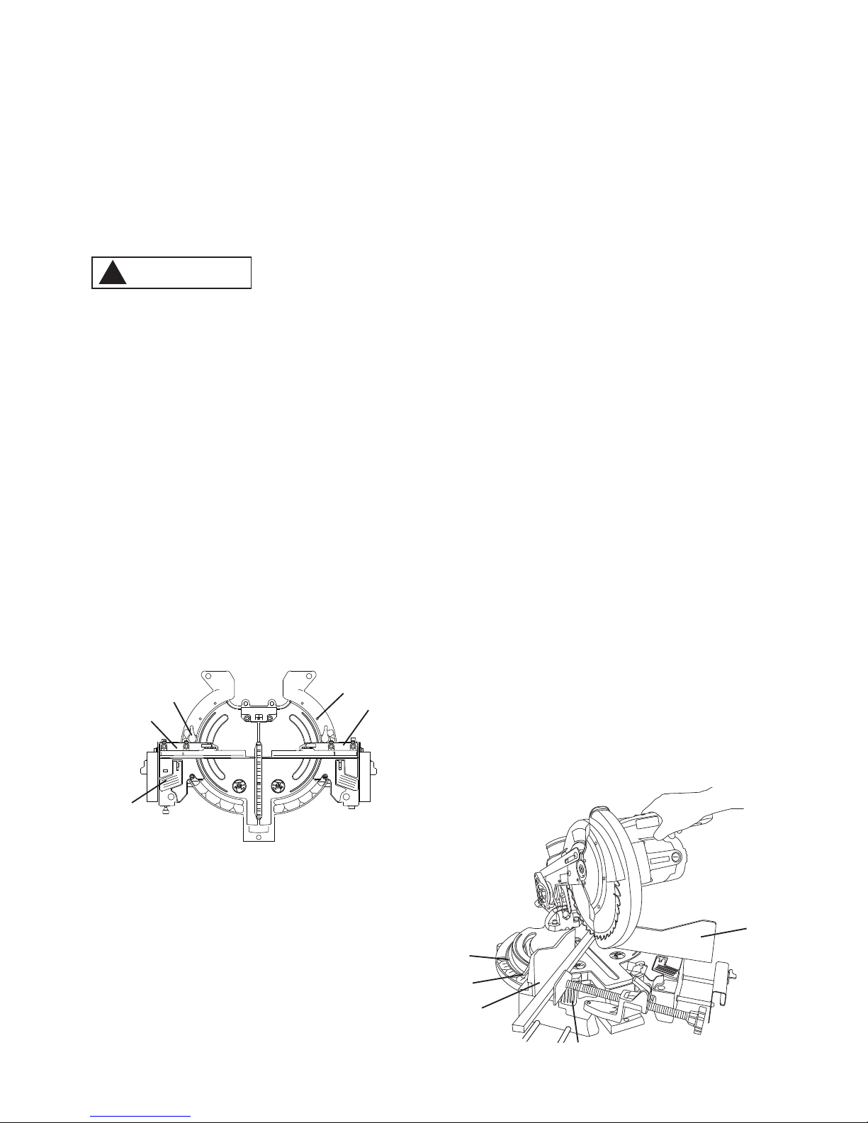
MITER ANGLE ADJUSTMENT (FIG. P)
NOTE: There are dual miter scales on
the miter saw. Each of the miter scales
assists the user in setting the desired
miter angle from 50° forward to 50°
backward. Each sliding table has most
common angle settings with positive
stops at 45°, 22.5° and 0°. These positive
stops position the sliding fence unit at the
desired angle quickly and accurately.
To Adjust the Angle:
1. Unlock the left sliding fence unit
by unlocking the positive stop lock
lever (1) behind the sliding fence
unit and lifting up the lock lever (2)
pivotally connected in the base.
2. Slide the left sliding fence unit forward
or backward to the desired angle.
3. If the desired angle is one of the
five detents (6), lock the positive
stop lock lever, and then flip the lock
lever down to lock the left sliding
fence unit.
4. If the desired angle is not one of the
five positive stops, simply lock the
left sliding fence unit by flipping the
lock lever down.
5. Adjust the angle of the right
sliding fence unit according to the
procedure foregoing 1–4.
To Adjust the Indicator:
1. Position the left sliding fence unit at
the positive stop angle 0° (refer to the
procedure of To adjust the angle),
loosen the bolt (3) and adjust the
indicator (4) to aim at the 0° mark on
the miter scale (5).
2. Adjust the indicator mounted on the
right sliding fence unit according to
the same way mentioned above.
Fig. P
3
1
2
3
4
5
1
2
6

ADJUSTING SLIDING FENCE UNITS
SQUARENESS AND ALIGNMENT
(FIG. Q, R, S)
1. Lower the cutting arm and lock in
position.
2. Using a square, lay the heel of the
square against the worktable, and
the rule against the blade. Check
to see if the angle between the
worktable and the blade is 90°.
3. If not, make the angle to be
90° by adjusting the bevel angle
adjustment bolt (1).
Fig. Q
4. Lay the heel of the square against
the blade, and the rule against the
left sliding fence unit (2) which is
positioned at positive stop angle
0°. Check to see if the angle
between the blade and the left
sliding fence unit is 90°. (Fig. R)
5. If not, unlock the left sliding fence
plate (3) by using a hex key to
loosen the three bolts (4) behind
the left slinding fence and two set
screws (5) vertically placed on the
lateral side of fence plate.
6. Adjust the left sliding fence plate (3)
to be perpendicular to the blade,
and then tighten the bolts (4) and
screws (5) to lock the plate.
7. Using a bar (6), lay the bar against
the left sliding fence unit (2) and
the right sliding fence unit (7) which
is also positioned at angle 0°, and
check to see if the left and right
sliding fence units are aligned on a
same line. (Fig. R, S)
Fig. S
8. If not, unlock the right sliding fence
plate (8) by using the hex key to
loosen the three bolts (4) behind
right sliding fence plate and two set
screws (5) vertically placed on the
lateral side of fence plate.
9. Adjust the right sliding fence plate (8)
into alignment with the left sliding
fence plate (3), and then tighten the
bolts (4) and screws (5) to lock the
right sliding fence plate.
1
Fig. R
2
3
4
5
6
7
8

18 19
5. Repeat until adjusted properly, and
tighten the locknut to secure the
adjustment bolt into position.
Fig. U
ADJUSTING THE CLAMP (FIG. V)
1. Rotate the knob (1)
counterclockwise to allow enough
room for the workpiece to fit
between the hold plate (2) and the
sliding fence unit.
2. The clamp incorporates a quickrelease lock lever (3). To use the
quick-release function, lift up the
quick-release lock lever and slide
the clamp forward or backward to
the desired position.
3. When the clamp plate is located at
the desired position, flip the quickrelease lock lever down to engage
the threads thereon with the threads
on the clamp, and rotate the knob
clockwise to secure the workpiece
within the hold plate and the sliding
fence unit.
NOTE: If intend to release the
workpiece from seccure status,
counterclockwise the knob first before
lifting up the quick-release lock lever.
Fig. V
1
2
ADJUSTING LOCK LEVERS (FIG. T)
After a period of use, the lock levers
might loosen and couldn’t clamp the
sliding fence units tightly.
An adjustment is needed.
1. Slightly lift up the miter saw base,
find out the location of lock nuts (1)
for both sides of lock levers. Properly
tighten the lock nuts and slightly lay
down the miter saw base.
NOTE: The adjustment of lock levers
have been completed at the factory.
Fig. T
CUTTING ARM TRAVEL
Cutting Arm Downward Travel
Adjustment (Fig. U)
To avoid injury from unexpected
starting or electrical shock, turn the
switch OFF and remove the power
cord from the power
source.
NOTE: Before each cutting operation,
check the position of the blade to make
sure it does not contact any metal surface.
If the blade contacts any metal surface,
the depth of travel must be adjusted.
1. Lower the blade as far as possible.
2. Loosen the locknut (1).
3. Turn the adjustment bolt (2) out
(counterclockwise) to decrease the
cutting depth or in (clockwise) to
increase the cutting depth.
4. Carefully rotate the blade manually
to check for contact. Avoid touching
blade points or edges.
WARNING
!
3
2
1
1

●
If you have any problem or question
on the laser guide, please call the
Service Center.
AVOID DIRECT EYE CONTACT
● Laser is radiated when laser
guide is turned on. Avoid direct
eye contact. Always un-plug the
miter saw from power source
before making any adjustments.
●
Laser Warning Label:
Max output < 5 mW DIODE
Wavelength: 630-660nm,
Complies with 21CFR 1040.10
and 1040. 11. (Fig. X)
●
Laser Aperture Label:
AVOID EXPOSURE: Laser
radiation is emitted from this
aperture. (Fig. X)
●
NOTE: All the adjustments for the
operation of this machine have
been completed at the factory.
Due to normal wear and use,
some occasional readjustments
may be necessary.
THE LASER GUIDE (FIG. W, X, Y)
For your own safety, never connect
the plug to a power source outlet
until all the adjustment steps
are complete and you have read
and understood the safety and
operational instructions.
Your tool is equipped with a laser guide
using a Class IIIa laser guide. The laser
guide allows you to preview the saw
blade path on the workpiece to be cut
before starting the miter saw. This laser
guide is powered by the transformed
alternating current supply directly
through the power lead. The saw must
be connected to the power source and
the laser on/off switch must be turned
on for the laser line to show.
TURNING SAW ON (FIG. W)
1. To turn laser on, turn switch (1) to
“I” position.
2. To turn laser off, turn switch to “O”
position.
Fig. W
NOTE:
●
All the adjustments for the operation
of the laser guide has been
completed at the factory.
●
Laser beam is calibrated and set up to
project to the left of the blade. (Fig. Y)
1
WARNING
!
LASER RADIATION-AVOID
DIRECT EYE EXPOSURE
Complies with 21 CFR 1040.10 and 1040.11
Max.Output <5 mW Wa
velength: 630-660 nm
WARNING
!
WARNING
!
WARNING
!
DANGER
!

20 21
● Use of controls or adjustments
or performance of procedures
other than those specified herein
may result in hazardous radiation
exposure.
● The use of optical instruments
with this product will increase
eye hazard.
●
Do not attempt to repair or
disassemble the laser. If unqualified
persons attempt to repair this laser
product, serious injury may result.
Any repair required on this laser
product should be performed by a
qualified service center.
A. Checking Laser Beam Alignment
(Fig. Y)
1. Mark a 90° straight line across the
top side and front side of a board to
serve as a “pattern line” to test laser
alignment. Lay the board on the
mitre table.
2. Turn the laser on and align the laser
beam with the pattern line.
3. Lower saw blade to pattern line.
If blade is not flush with the
pattern line, adjust the laser as in
procedures B and C.
Fig. X
B. Adjusting the Translation Position
of the Laser Beam (Fig. X, Y)
1. Loosen two securing screws (3)
slightly. (Fig. X)
2. Hold the laser assembly (2) to move
the laser element (1) toward left or
right for adjusting the translation
position of laser beam.
3. Once alignment of the laser is
achieved, tighten the securing
screws (3).
C. Aligning the Laser Beam (Fig. X, Y)
1. Loosen two securing screws (3)
slightly. (Fig. X)
2. Turn slightly the laser assembly (2)
for adjusting the horizontal angle
of the laser beam. When the laser
beam slopes from left to right,
turn the laser assembly (2) anticlockwise; when the laser beam
slopes from right to left, turn the
laser assembly (2) clockwise until
alignment of the laser is achieved.
3. Once alignment of the laser is
achieved, tighten the securing
screws (3).
Fig. Y
Cutting
Line
Laser Beam
Workpiece
Blade
Move
Toward Left
Move
Toward Right
Anti-clockwise
Clockwise
Blade
Left Side View
Right Side View
Laser Aperture
Label
Laser Warning Label
LASER RADIATION-AV
OID
DIRECT EYE EX
POSURE
Complies w
it
h 21
CFR 1040
.10 and 1040.11
Max.Output <5 mW Wa
velength: 630-660 nm
1
2
3
1
2
3

SAFETY INSTRUCTIONS FOR BASIC
SAW OPERATION
BEFORE USING THE MITER SAW
To avoid mistakes that could cause
serious, permanent injury, do not
plug the tool in until the following
steps are completed:
● Completely assemble and adjust
the saw, following the instructions.
(ASSEMBLY & ADJUSTMENTS)
● Learn the use and function of the
ON/OFF switch, lock-off switch,
upper and lower blade guards, head
lock down knob, bevel lock handle
and cover plate screws.
● Review and understand
all safety instructions and
operating procedures in this
Instruction Manual. (SAFETY &
OPERATIONS)
● Review the MAINTENANCE and
TROUBLESHOOTING GUIDE for
your miter saw.
● To avoid injury or possible death
from electrical shock:
Make sure your fingers do not
touch the plug’s metal prongs
when plugging or unplugging
your miter saw. (ELECTRICAL
EQUIREMENTS AND SAFETY)
BEFORE EACH USE INSPECT YOUR
SAW.
● Disconnect the miter saw.
To avoid injury from accidental
starting, unplug the saw before any
adjustments, including set-up and
blade changes.
WARNING
!
● Compare the direction of rotation
arrow on the guard to the direction
arrow on the blade. The blade teeth
should always point downward at
the front of the saw.
● Tighten the arbor bolt.
● Tighten the cover plate screw.
● Check for damaged parts.
Check for:
● Alignment of moving parts
● Damaged electric cords
● Binding of moving parts
● Mounting holes
● Function of arm return spring
and lower guard: Push the
cutting arm all the way down,
then let it rise until it stops.
The lower guard should fully
close. Follow instructions in
TROUBLESHOOTING GUIDE
for adjustment if necessary.
● Other conditions that may affect
the way the miter saw works.
● Keep all guards in place, in working
order and proper adjustment. If any
part of this miter saw is missing,
bent, damaged or broken in any
way, or any electrical parts don’t
work, turn the saw off and unplug it.
● Replace bent, damaged, missing or
defective parts before using the saw
again.
● Maintain tools with care. Keep the
miter saw clean for best and safest
performance. Follow instructions for
lubricating. Do not put lubricants on
the blade while it is spinning.
● Remove adjusting wrench from the
tool before turning it on.
● To avoid injury from jams, slips,
or thrown pieces, use only
recommended accessories.
OPERATION

22 23
SAFETY INSTRUCTIONS FOR BASIC
SAW OPERATION
BEFORE USING THE MITER SAW
To avoid mistakes that could cause
serious, permanent injury, do not
plug the tool in until the following
steps are completed:
● Completely assemble and adjust
the saw, following the instructions.
(ASSEMBLY & ADJUSTMENTS)
● Learn the use and function of the
ON/OFF switch, lock-off switch,
upper and lower blade guards, head
lock down knob, bevel lock handle
and cover plate screws.
● Review and understand
all safety instructions and
operating procedures in this
Instruction Manual. (SAFETY &
OPERATIONS)
● Review the MAINTENANCE and
TROUBLESHOOTING GUIDE for
your miter saw.
● To avoid injury or possible death
from electrical shock:
Make sure your fingers do not
touch the plug’s metal prongs
when plugging or unplugging
your miter saw. (ELECTRICAL
EQUIREMENTS AND SAFETY)
BEFORE EACH USE INSPECT YOUR
SAW.
● Disconnect the miter saw.
To avoid injury from accidental
starting, unplug the saw before any
adjustments, including set-up and
blade changes.
● Compare the direction of rotation
arrow on the guard to the direction
arrow on the blade. The blade teeth
should always point downward at
the front of the saw.
WARNING
!
● Tighten the arbor bolt.
● Tighten the cover plate screw.
● Check for damaged parts.
Check for:
● Alignment of moving parts
● Damaged electric cords
● Binding of moving parts
● Mounting holes
● Function of arm return spring
and lower guard: Push the
cutting arm all the way down,
then let it rise until it stops.
The lower guard should fully
close. Follow instructions in
TROUBLESHOOTING GUIDE
for adjustment if necessary.
● Other conditions that may affect
the way the miter saw works.
● Keep all guards in place, in working
order and proper adjustment. If any
part of this miter saw is missing,
bent, damaged or broken in any
way, or any electrical parts don’t
work, turn the saw off and unplug it.
● Replace bent, damaged, missing or
defective parts before using the saw
again.
● Maintain tools with care. Keep the
miter saw clean for best and safest
performance. Follow instructions for
lubricating. Do not put lubricants on
the blade while it is spinning.
● Remove adjusting wrench from the
tool before turning it on.
● To avoid injury from jams, slips,
or thrown pieces, use only
recommended accessories.
● Check the dust bag before you
work. Empty the bag if it is more
than half-full.
KEEP YOUR WORK AREA CLEAN
Cluttered areas and benches invite
accidents.

To avoid burns or other fire damage,
never use the miter saw near
flammable liquids, vapors, or gases.
● Plan ahead to protect your eyes,
hands, face and ears.
● Know your miter saw. Read and
understand this Instruction Manual
and labels affixed to this tool. Learn
its application and limitations as well
as the specific potential hazards
peculiar to this tool. To avoid injury
from accidental contact with moving
parts, do not do layout, assembly, or
setup work on the miter saw while
any parts are moving.
● Avoid accidental starting, make sure
the trigger switch is disengaged
before plugging the miter saw into a
power outlet.
PLAN YOUR WORK
● Use the right tool. Don’t force a tool
or attachment to do a job it was not
designed to do. Use a different tool
for any workpiece that can’t be held
in a solidly braced, fixed position.
This machine is not designed for
cutting masonry, masonry products,
ferrous metals (steel, iron, and ironbased metals.) Use this miter saw to
cut only wood, wood-like products,
or non-ferrous metals. Other
material may shatter, bind the blade,
or create other dangers. Remove all
nails that may be in the workpiece to
prevent sparking that could cause a
fire. Remove dust bag when cutting
non-ferrous metals.
DRESS FOR SAFETY
Any power tool can throw
foreign objects into the eyes.
This can result in permanent
eye damage. Everyday
eyeglasses have only impact resistant
lenses and are not safety glasses.
Glasses or goggles not in compliance
with ANSI Z87.1 could seriously injure
you when they break.
● Do not wear loose clothing, gloves,
neckties or jewelry (rings, watches).
They can get caught and draw you
into moving parts.
● Wear non-slip footwear.
● Tie back long hair.
● Roll long sleeves above the elbow.
● Noise levels vary widely. To avoid
possible hearing damage, wear ear
plugs when using any miter saw.
● For dusty operations, wear a dust
mask along with safety goggles.
INSPECT YOUR WORKPIECE
Make sure there are no nails or foreign
objects in the part of the workpiece
being cut. Plan your work to avoid small
pieces that may bind, or that are too
small to clamp and get a solid grasp on.
Plan the way you will grasp the
workpiece from start to finish. Avoid
awkward operations and hand positions.
A sudden slip could cause your fingers
or hand to move into the blade.
DO NOT OVER-REACH
Keep good footing and balance. Keep
your face and body to one side, out of
the line of a possible kickback. NEVER
stand in the line of the blade.
Never cut freehand:
● Brace your workpiece firmly against
the fence and table stop so it will
not rock or twist during the cut.
● Make sure there is no debris between
the workpiece and the table or fence.
WARNING
!
CAUTION
!

24 25
To avoid injury, follow all applicable
safety instructions, when cutting
non-ferrous metals:
● Use only saw blades specifically
recommended for non-ferrous
metal cutting.
● Do not cut metal workpieces
that must be hand held. Clamp
workpieces securely.
● Cut non-ferrous metals only if you
are under the supervision of an
experienced person and the dust bag
has been removed from the saw.
WHEN SAW IS RUNNING
Do not allow familiarity from
frequent use of your miter saw
to result in a careless mistake.
A careless fraction of a second is
enough to cause a severe injury.
Before cutting, if the saw makes an
unfamiliar noise or vibrates, stop
immediately. Turn the saw OFF.
Unplug the saw. Do not restart until
finding and correcting the problem.
BODY AND HAND POSITION (FIG. Z)
Never place hands near
the cutting area. Proper
positioning of your body and
hands when operating the miter
saw will make cutting easier and
safer. Keep children away. Keep all
visitors at a safe distance from the
miter saw. Make sure bystanders
are clear of the saw and workpiece.
Don’t force the saw. It will do the job
better and safer at its designed rate.
WARNING
!
WARNING
!
● Make sure there are no gaps
between the workpiece, fence and
table that will let the workpiece shift
after it is cut.
● Keep the cut off piece free to move
sideways after it is cut off. Otherwise,
it could get wedged against the
blade and thrown violently.
● Only the workpiece should be on
the saw table.
● Secure work. Use clamps or a vise to
help hold the work when it’s practical.
USE EXTRA CAUTION WITH LARGE
OR ODD SHAPED WORKPIECES.
● Use extra supports (tables,
sawhorses, blocks, etc.) for
workpieces large enough to tip.
● Never use another person as a
substitute for a table extension, or as
an additional support for a workpiece
that is longer or wider than the basic
miter saw table, or to help feed,
support, or pull the workpiece.
● Do not use this saw to cut small
pieces. If the workpiece being cut
would cause your hand or fingers to
be within 15.2 cm of the saw blade
the workpiece is too small. Keep
hands and fingers out of the “no
hands zone” area marked on the
saw table.
● When cutting odd shaped
workpieces, plan your work so it
will not bind in the blade and cause
possible injury. Molding, for example,
must lie flat or be held by a fixture or
jig that will not let it move when cut.
● Properly support round material
such as dowel rods, or tubing, which
have a tendency to roll when cut,
causing the blade to “bite”.
WARNING
!

BASIC SAW OPERATIONS
For your convenience, your saw
has a blade brake. The brake is
not a safety device. Never rely on
it to replace the proper use of the
guard on your saw. If the blade
doesn’t stop within approximately 6
seconds, wait for the blade to stop,
unplug the saw and contact Service
Center.
TURNING SAW ON (FIG. AA)
To reduce the likelihood of accidental
starting, a thumb activated lock-off
switch is located on top of the switch
handle. The lock-off switch (1) must
be pushed in before the trigger switch
(2) can be activated and the miter saw
started.
Make the switch child-proof. Insert
a padlock through the hole (3) in
the trigger switch and lock it. This
will prevent children and other
unauthorized users from engaging
the trigger switch ON.
Fig. AA
WARNING
!
WARNING
!
Starting a cut:
● Place hands at least 15.2 cm away
from the path of the blade – out of
the “no-hands zone” (1).
● Hold workpiece firmly against the
fence to prevent movement toward
the blade.
● With the power switch OFF,
bring the saw blade down to the
workpiece to see the cutting path of
the blade.
● Press in lock-off switch in trigger
switch handle.
● Squeeze trigger switch to start saw.
● Lower blade into workpiece with a
firm downward motion.
Finishing a cut:
● Hold the cutting arm in the down
position.
● Release trigger switch and wait
for all moving parts to stop before
moving your hands and raising the
cutting arm.
● If the blade doesn’t stop within
6 seconds, unplug the saw
and follow the instructions in
TROUBLESHOOTING GUIDE
section.
Before freeing jammed material:
● Release trigger switch.
● Wait for all moving parts to stop.
● Unplug the miter saw.
Fig. Z
15.2 cm 15.2 cm
1
1
2
3
26 27
BEFORE LEAVING THE SAW
● Never leave tool running
unattended. Turn power OFF. Wait
for all moving parts to stop and
unplug unit from power source.
● Make workshop child-proof. Lock the
shop. Disconnect master switches.
Store tool away from children and
other unqualified users.
To avoid injury from materials being
thrown, always unplug the saw
to avoid accidental starting , and
remove small pieces of material
from the table cavity.
MITER CUT (FIG. BB, CC)
1. Choose the left or right sliding fence
unit to perform the miter cutting.
2. If the left sliding fence unit (1) is
chosen, unlock the left sliding fence
unit by unlocking the positive stop
lock lever (2) behind the left sliding
fence unit and lifting up the lock lever
(3) pivotally connected in the base.
Fig. BB
3. Slide the left sliding fence unit to
the desired angle from 0° to 50°
forward.
4. If the desired angle is one of the
positive stops (4), engage the
positive stop lock lever, and then
flip the lock lever down to lock the
sliding fence unit. Positive stops
for miter cutting are provided at 0°,
22.5° and 45°.
5. If the desired angle is not one of
positive stops, simply lock the
sliding fence unit by flipping the lock
lever down.
6. For avoiding the interference
caused by the right sliding fence
unit (5) during cutting operation,
lock the right sliding fence at the
angle 45° forward.
7. Unlock the right sliding fence plate
by loosening the knob, and slide the
right sliding fence plate rightward to
the distal end, and tighten the knob.
8. Place the workpiece against the left
sliding fence unit and secure the
workpice by the vise to perform the
miter cutting.
9. If the right sliding fence unit is
chosen, inversely adjust the two
sliding fence units according to the
procedure foregoing 2–8.
IMPORTANT:Make sure both sliding
fences are secure and tight before
beginning any cutting operation.
IMPORANT: Make sure that both sides
of the sliding fences are positioned
so that they do not contact the saw
blade. Check this before plugging in
and starting the saw. Secure and Lock
into position before making any cutting
operations.
Fig. CC
2
3
1
4
5
WARNING
!
3
1
4
2
5

3.
If the desired angle is one of the
positive stops, tighten the positive stop
lock lever, and then flip the lock lever
down to lock the sliding fence unit.
Positive stops for compound cutting
are provided at 0°, 22.5° and 45°.
4. If the desired angle is not one of
positive stops, simply lock the
sliding fence unit by flipping the lock
lever down.
5.
Unlock the left sliding fence plate by
loosening the knob, and slide the left
sliding fence plate leftward for avoiding
interference, and tighten the knob.
6. Lock the right sliding fence at the
angle 45° forward, loosen the knob,
and slide the right sliding fence plate
rightward to the distal end for avoiding
interference, then tighten the knob.
7. Loosen the bevel lock handle and
position the cutting head at the
desired bevel angle which can be
read from the bevel scale, and then
tighten the bevel lock handle.
8. Place the workpiece against the left
sliding fence plate and secure the
workpice by the vise to perform the
compound cutting.
IMPORTANT: Make sure both sliding
fences are secure and tight before
beginning any cutting operation.
Fig. EE
BEVEL CUT (FIG. DD)
1. When a bevel cut is required,
loosen the bevel lock handle for
angle adjusting.
2. Tilt the cutting head to the desired
angle as shown on the bevel scale
(1). The blade can be positioned at
any angle, from a 90° straight cut
(0° on the scale) to a 45° left bevel.
3. Unlock the left sliding fence plate
by loosening the knob, and slide
the plate leftward for avoiding
interference, and tighten the knob.
4. Tighten the bevel lock handle to
lock the cutting head in position.
5. Positive stops are provided at 0°
and 45°.
IMPORTANT:Make sure both sliding
fences are secure and tight before
beginning any cutting operation.
Fig. DD
COMPOUND CUT (FIG. EE)
A compound cut is the combination of
a miter and a bevel cut simultaneously.
1. Unlock the left sliding fence unit
by unlocking the positive stop lock
lever behind the left sliding fence
unit and lifting up the lock lever
pivotally connected in the base.
2. Slide the left sliding fence unit to the
desired angle from 0°~ 50° forward.
1

28 29
Fig. HH
a) For inside corner, adjust the
paddles to make the angle (X1)
between two paddles larger than
the inside corner angle (X2), and
then butt each paddle flat against
the wall surface.
b) For outside corner, adjust the
paddles to make the angle (Y1)
between two paddles smaller than
the outside corner angle (Y2), and
then utt each paddle flat against
the wall surface.
2. Tighten the knob to the lock position
and remove the MiterMate™ angle
finder from the corner.
Adjusting the sliding fences for
miter angle setting (Fig. II):
1. Place the angle copied MiterMate™
angle finder on the saw. Make sure
the fitting block (3-Fig. II) under the
MiterMate™ angle finder is inserted
into the slot (4) through table.
2. Individually unlock the left and right
sliding fence units by unlocking the
positive stop lock lever (5) behind the
fence unit and lift up the lock lever (6)
pivotally connected in the base.
3. Individually slide the left and right
sliding fence units toward the
paddles until each sliding fence
plate (7) flat against the paddle (8).
WORKPIECE SUPPORT AND
REPETITIVE CUTTING USING THE
STOP PLATE (FIG. FF)
Long workpieces need to be supported
by the extension wing.
1. Slide the extension wing to desired
position and tighten the knob.
2. The stop plate (1) is designed for
use during repetitive cutting. Only
use one stop plate a time. To use
this function, simply rotate the stop
plate to vertical position.
Fig. FF
SETTING UP THE TABLES FOR
ANGLE CUTS USING THE MiterMate™
ANGLE FINDER (FIG. GG, HH)
The Miter accurate angle cutting is
suited to do with the fact that most
walls and ceiling are not 90 degrees to
each other, and so you can make the
accurate angles for fewer miscut and
quicker task completion.
Using the MiterMate™ angle finder to
copy a corner angle:
1. Unlock the MiterMate™ angle finder
by loosening the knob (1), open up
the paddles (2) to copy the corner
angle.
Fig. GG
1
2
3
1
X2
X1
Y1
Y2
Inside Corner
Outside Corner

4. Individually lock the left and right
sliding fence units by flipping down
the lock lever (6).
5. Remove the MiterMate™ angle
finder from the saw.
6. Respectively place a base/crown
molding piece against the left and
right sliding fence units, and perform
the cross cutting to accomplish
base/crown molding cutting.
Fig. II
Cutting crown molding:
Your miter saw is suited for making the
difficult task of cutting crown molding
easily. To fit properly, crown molding
must be cut with extreme accuracy.
The two surfaces on a piece of crown
molding that fit flat against the ceiling
and wall are at angles that, when
added together equal exactly 90°. Most
crown molding has a top rear angle (the
section that fits flat against the ceiling)
and a bottom rear angle (the section
that fits flat against the wall). The
two common spring angles for crown
molding are: 52°/38° and 45°/45°.
1. Determine the spring angle for the
crown molding, for example, 52/38
degrees as shown in Fig. JJ.
Fig. JJ
2. Measure the angle of corner by
MiterMate™ angle finder and lock
the sliding fences unit in positions.
3. Place the crown molding piece
upside down with against the table
and the fence as shown in Fig. JJ.
(Think of the table as the ceiling.)
Fig. KK
4. Use the clamp to secure the
molding piece and hold it at the
proper spring angle.
NOTE: Use the extension wings to
steady long molding pieces.
5. Cut on the side of the saw as shown
in the following chart.
NOTE: If molding piece is too tall,
cut flat using the instructions of a
conventional way on page 30.
4
6
7
8
5
F
e
n
c
e
Miter saw table
Clamp
52°
38°
Ceiling
Wall
52°
38°
Ceiling/Wall (Crown Molding Orientation)
Orientation
Inside corner Outside corner
Right
side of
wall
Left
side of
wall
Right
side of
wall
Left
side of
wall
Cut on this
side of the saw
Left Right Left Right

30 31
Cutting base molding:
Base moldings and many other
moldings can be cut on your miter
saw. The setup of the saw depends on
molding characteristics and application.
Perform practice cuts on scrap material
to achieve best results.
1. Place the base molding piece
upside against the fence and table
as shown in Fig. LL.
Fig. LL
2. Measure the angle of corner by
MiterMate™ angle finder and lock
the sliding fences unit in positions.
3. Use the clamp to secure the base
molding piece.
NOTE: Use the telescoping
extension wings to support long
molding pieces.
4. Cut on the side of the saw as shown
in the following chart.
NOTE: If molding piece is too tall, reset
fences to 0° and cut flat using the bevel
like a conventional saw.
CONVENTIONAL WAY OF CUTTING
CROWN/BASE MOLDING
The following instructions are not the
optimum way to cut molding using
the miter cutting feature. Use these
instructions only for cutting molding too
large for the Miter feature.
Cutting base molding (Fig. MM):
Base moldings and many other
moldings can be cut on a compound
miter saw. The setup of the saw
depends on molding characteristics
and application, as shown. Perform
practice cuts on scrap material to
achieve best results:
1. Always make sure moldings rest
firmly against fence and table. Use
hold-down or C-clamps, whenever
possible, and place tape on the
area being clamped to avoid marks.
2. Reduce splintering by taping the cut
area prior to making cut. Mark cut
line directly on the tape.
3. Splintering typically happens due
to wrong blade application and
thinness of the material.
Fig. MM
NOTE: Always perform a dry run cut
so you can determine if the operation
being attempted is possible before
power is applied to the saw.
Wall/Ground (Base Molding Orientation)
Orientation
Inside corner Outside corner
Right
side of
wall
Left
side of
wall
Right
side of
wall
Left
side of
wall
Cut on this
side of the saw
Right Left Right Left
Miter at 45°, Bevel at 0°
Workpiece
F
e
n
c
e
Miter Saw Table
Miter at 0°, Bevel at 45°
Workpiece
Miter Saw Table
F
e
n
c
e

Fig. NN
Bevel/Miter Settings
Fig. OO
Settings for standard crown molding
lying flat on compound miter saw
table
Cutting crown molding
(Fig. NN, OO):
Your compound miter saw is suited
for the difficult task of cutting crown
molding. To fit properly, crown molding
must be cut with extreme accuracy.
The two surfaces on a piece of crown
molding that fit flat against the ceiling
and wall are at angles that, when
added together equal exactly 90°.
In order to accurately cut crown
molding for a 90° inside or outside
corner, lay the molding with its broad
back surface flat on the saw table.
When setting the bevel and miter angles
for compound miters, remember that the
settings are interdependent; changing
one changes the other, as well.
IL
EI
ED
ID
Outside Corner
Inside Corner
Workpiece
Miter Saw Table
F
e
n
c
e
NOTE: The chart below references a compound cut for crown molding ONLY
WHEN THE ANGLE BETWEEN THE WALLS EQUALS EXACTLY 90°.
KEY
BEVEL
SETTING
MITER SETTING TYPE OF CUT
Inside corner - Left side
IL 33.9° 31.6° Right
1. Position top of molding against fence.
2. Miter table set at RIGHT 31.6°.
3. LEFT side is finished piece.
Inside corner - Right side
IR 33.9° 31.6° Left
1. Position bottom of molding against fence.
2. Miter table set at LEFT 31.6°.
3. LEFT side is finished piece.
Outside corner - Left side
OL 33.9° 31.6° Left
1. Position bottom of molding against fence.
2. Miter table set at LEFT 31.6°.
3. RIGHT side is finished piece.
Outside corner - Right side
OR 33.9° 31.6° Right
1. Position top of molding against fence.
2. Miter table set at RIGHT 31.6°.
3. RIGHT side is finished piece.

32 33
CROWN MOLDING CHART
MiterMate™ Miter Saw
Miter and Bevel Angle Settings
Wall to Crown Molding Angle
52/38° Crown Molding 45/45° Crown Molding 52/38° Crown Molding 45/45° Crown Molding
Angle
Between
Walls
Miter Setting Bevel Setting
Miter
Setting
Bevel
Setting
Angle
Between
Walls
Miter
Setting
Bevel
Setting
Miter
Setting
Bevel
Setting
67 42.39 41.08 46.69 36.13 124 18.13 21.71 20.61 19.39
68 42.39 40.79 46.35 35.89 125 17.77 21.34 20.21 19.06
69 41.85 40.50 45.81 35.64 126 17.42 20.96 19.81 18.72
70 41.32 40.20 45.28 35.40 127 17.06 20.59 19.42 18.39
71 40.79 39.90 44.75 35.15 128 16.71 20.21 19.03 18.06
72 40.28 39.61 44.22 34.89 129 16.37 19.83 18.64 17.72
73 39.76 39.30 43.70 34.64 130 16.02 19.45 18.25 17.39
74 39.25 39.00 43.18 35.38 131 15.67 19.07 17.86 17.05
75 38.74 38.69 42.66 34.12 132 15.33 18.69 17.48 16.71
76 38.24 38.39 42.15 33.86 133 14.99 18.31 17.09 16.38
77 37.74 38.08 41.64 33.60 134 14.66 17.93 16.71 16.04
78 37.24 37.76 41.13 33.33 135 14.30 17.55 16.32 15.70
79 36.75 37.45 40.62 33.07 136 13.97 17.17 15.94 15.36
80 36.27 37.13 40.12 32.08 137 13.63 16.79 15.56 15.02
81 35.79 36.81 39.62 32.53 138 13.30 16.40 15.19 14.62
82 35.31 36.49 39.13 32.25 139 12.96 16.02 14.81 14.34
83 34.83 36.17 38.63 31.98 140 12.63 15.64 14.43 14.00
84 34.36 35.85 38.14 31.70 141 12.30 15.25 14.06 13.65
85 33.90 35.52 37.66 31.42 142 11.97 14.87 13.68 13.31
86 33.43 35.19 37.17 31.34 143 11.64 14.48 13.31 12.97
87 32.97 34.86 36.69 30.86 144 11.31 14.09 12.94 12.62
88 32.52 34.53 36.21 30.57 145 10.99 13.71 12.57 12.29
89 32.07 34.20 35.74 30.29 146 10.66 13.32 12.20 11.93
90 31.62 33.86 35.26 30.00 147 10.34 12.93 11.83 11.59
91 31.17 33.53 34.79 29.71 148 10.01 12.54 11.46 11.24
92 30.73 33.19 34.33 29.42 149 9.69 12.16 11.09 10.89
93 30.30 32.86 33.86 29.13 150 9.37 11.77 10.73 10.55
94 29.86 32.51 33.40 28.83 151 9.05 11.38 10.36 10.20
95 29.43 32.17 32.94 28.54 152 8.73 10.99 10.00 9.85
96 29.00 31.82 32.48 28.24 153 8.41 10.60 9.63 9.50
97 28.58 31.48 32.02 27.94 154 8.09 10.21 9.27 9.15
98 28.16 31.13 31.58 27.64 155 7.77 9.82 8.91 8.80
99 27.74 30.78 31.13 27.34 156 7.46 9.43 8.55 8.45
100 27.32 30.43 30.68 27.03 157 7.14 9.04 8.19 8.10
101 26.91 30.08 30.24 26.73 158 6.82 8.65 7.83 7.75
102 26.50 29.73 29.80 26.42 159 6.51 8.26 7.47 7.40
103 26.09 29.38 29.36 26.12 160 6.20 7.86 7.11 7.05
104 25.69 29.02 28.92 25.81 161 5.88 7.47 6.75 6.70
105 25.29 28.67 28.48 25.50 162 5.57 7.08 6.39 6.35
106 24.89 28.31 28.05 25.19 163 5.26 6.69 6.03 6.00
107 24.49 27.96 27.62 24.87 164 4.95 6.30 5.68 5.65
108 24.10 27.59 27.19 24.56 165 4.63 5.90 5.32 5.30
109 23.71 27.23 26.77 24.24 166 4.32 5.51 4.96 4.94
110 23.32 26.87 26.34 23.93 167 4.01 5.12 4.61 4.59
111 22.93 26.51 25.92 23.61 168 3.70 4.72 4.25 4.24
112 22.55 26.15 25.50 23.29 169 3.39 4.33 3.90 3.89
113 22.17 25.78 25.08 22.97 170 3.08 3.94 3.54 3.53
114 21.79 25.42 24.66 22.66 171 2.77 3.54 3.19 3.10
115 21.42 25.05 24.25 22.33 172 2.47 3.15 2.83 2.83
116 21.04 24.68 23.84 22.01 173 2.15 2.75 2.48 2.47
117 20.67 24.31 23.43 21.68 174 1.85 2.36 2.12 2.12
118 20.30 23.94 23.02 21.36 175 1.54 1.97 1.77 1.77
119 19.93 23.57 22.61 21.03 176 1.23 1.58 1.41 1.41
120 19.57 23.20 22.21 20.70 177 0.92 1.18 1.06 1.06
121 19.20 22.83 21.80 20.38 178 0.62 0.79 0.71 0.71
122 18.84 22.46 21.40 20.05 179 0.31 0.39 0.35 0.35
123 18.48 22.09 21.00 19.72

NOTE: To reinstall the same brushes,
first make sure the brushes go back in
the way they came out. This will avoid
a break-in period that reduces motor
performance and increases wear.
Fig. PP
●
When cleaning the lower guard,
unplug the saw from the power
source receptacle to avoid
unexpected startup.
● Do not use solvents on the
guard. They could make the
plastic “cloudy” and brittle.
EMPTYING SAWDUST BAG
Periodically, sawdust will accumulate
under the work table and base. This
could cause difficulty in the movement
of the worktable when setting up
a miter cut. Frequently blow out or
vacuum up the sawdust.
Wear proper eye protection to keep
debris from entering eyes when
removing sawdust from unit.
CHECKING AND TIGHTENING THE
TABLE LOCK LEVER
After a period of use, the lock levers
might loosen and couldn’t clamp the
sliding fence units tightly.
An adjustment is needed. Please see
ADJUSTING LOCK LEVERS section
on page 18.
MAINTENANCE
To avoid injury, never put lubricants
on the blade while it is spinning.
●
To avoid fire or toxic reaction,
never use gasoline, naphtha
acetone, lacquer thinner or
similar highly volatile solvents to
clean the miter saw.
● To avoid injury from unexpected
starting or electrical shock,
unplug the power cord before
working on the saw.
● For your safety, this saw is
double-insulated. To avoid
electrical shock, fire or injury,
use only parts identical to
those identified in the parts
list. Reassemble exactly as
the original assembly to avoid
electrical shock.
REPLACING CARBON BRUSHES
(FIG. PP)
Replace both carbon brushes when
either has less than 6.35 mm length
of carbon remaining, or if the spring or
wire is damaged or burned. To inspect
or replace brushes, first unplug the
saw. Then remove the black plastic
cap (1) on the side of the motor (2).
Remove the cap cautiously, because
it is springloaded. Then pull out the
brush and replace. Replace for the
other side. To reassemble reverse the
procedure. The ears on the metal end
of the assembly go in the same hole
the carbon part fits into. Tighten the
cap snugly, but do not overtighten.
DANGER
!
WARNING
!
WARNING
!
MAINTENANCE
1
2

34 35
To avoid injury from accidental starting, always turn switch OFF and unplug
the tool before moving, replacing the blade or making adjustments.
TROUBLESHOOTING GUIDE - MOTOR
PROBLEM PROBLEM CAUSE SUGGESTED CORRECTIVE ACTION
Brake does
not stop
blade within 6
seconds.
1. Motor brushes not sealed or
lightly sticking.
2. Motor brake overheated from
use of defective or wrong size
blade or rapid ON/OFF cycling.
3. Arbor bolt loose.
4. Brushes cracked, damaged,
etc.
5. Other.
1. Inspect/clean/replace brushes. See
MAINTENANCE section.
2. Use a recommended blade. Let
cool down. See REMOVING OR
INSTALLING THE BLADE section.
3. Retighten. See REMOVING OR
INSTALLING THE BLADE section.
4. Replace brushes.
5. Contact Service Center.
Motor does
not start.
1. Limit switch failure
2. Brush worn.
3. Fuse blown or circuit breaker
tripped on home panel.
1. Replace limit switch.
2. Replace brushes. See
MAINTENANCE section.
3. Verify there is electrical power at the
outlet.
Brush spark
when switch
released.
1. Brush worn.
2. Other.
1. Replace brushes. See
MAINTENANCE section.
2. Contact Service Center.
WARNING
!
TROUBLESHOOTING GUIDE
PROBLEM PROBLEM CAUSE SUGGESTED CORRECTIVE ACTION
Blade hits table. 1. Misalignment. 1. See ADJUSTMENT- CUTTING
ARM TRAVEL section.
Angle of cut not
accurate. Can not
adjust miter.
1. Miter table unlocked.
2. Sawdust under table.
1. See OPERATION - Miter Angle
Adjustment section.
2.
Vacuum or blow out dust. WEAR EYE
PROTECTION.
Cutting arm wobbles. 1. Loose pivot points. 1. Contact Service Center.
Cutting arm will not
fully raise, or blade
guard won’t fully close.
1. Pivot spring not
replaced properly after
service.
2. Sawdust build-up.
1. Clean and lubricate moving parts.
2. Contact Service Center.
Blade binds, jams,
burns wood.
1. Improper operation.
2. Dull or warped blade.
3. Improper blade size.
4 Wood is moving during
cut.
1. See BASIC SAW OPERATION
section.
2. Replace or sharpen blade.
3. Replace with 254 mm diameter
blade.
4. Use clamp to secure workpiece to
fenceunit and table.
Saw vibrates or
shakes.
1. Saw blade not round /
damaged / loose.
2. Arbor bolt loose.
1. Replace blade.
2. Tighten arbor bolt.
TROUBLESHOOTING GUIDE - SAW OPERATION

10 IN. (254 MM) MiterMateTM COMPOUND MITER SAW
When servicing use only REXON replacement parts. Use of any other parts
many create a HAZARD or cause product damage. Any attempt to repair
or replace electrical parts on this Miter Saw may create a HAZARD unless
repair is done by a qualified service technician. Repair service is available
at your nearest Service Center.
PARTS LIST FOR SAW SCHEMATIC A
WARNING
!
PARTS LIST
I.D. Description Size Q’ty I.D. Description Size Q’ty
0831 SHAFT SLEEVE 1 25Q0 WARNING LABEL 1
083Y COMPRESSION SPRING 1 2CA8
CR. RE. TRUSS HD. ROUND NECK SCREW
M6*1.0-12 1
083Z CORD CLAMP 1 2E35 TRIGGER 1
0CES COMPRESSION SPRING 1 2E7D
CR. RE. PAN HD. ROUND NECK SCREW
M6*1.0-9 1
0D87 TORSION SPRING 1 2FGW CONTROLLER ASS’Y 1
0D9B ANCHOR BLOCK 1 2FJF LEAD WIRE ASS’Y 1
0DHT SPRING GUARD WD=φ1.3 1 2T9B ROCK SWITCH ASS’Y 1
0DTZ ARBOR COLLAR 2 2V8U PC-GUARD ASS’Y 1
0DVJ BLADE WRENCH 1 2VFP ARM 1
0F1H COLLAR 1 2VFQ LASER SET 1
0J4C FLAT WASHER φ4*8-1 1 2VFR CABLE SHIELD 1
0J4E FLAT WASHER φ6*13-1 1 2VGB BRACKET 1
0JB0 WAVE WASHER WW-8 1 2VGS AXLE SEAT 2
0JVY HEX. SOC. HD. CAP BOLT M6*1.0-16 1 2VGU LASER PLUNGER HOUSING 1
0JZD HEX. SOC. SET SCREW M5*0.8-10 2 2VGW PIN 1
0JZN ARBOR BOLT M8*1.25-20 1 2VKG BRACKET 1
0K5C CR. RE. COUNT HD. SCREW M6*1.0-16 1 2VRT CUTTER SHAFT GUARD 1
0K74 CR. RE. TRUSS HD. SCREW M6*1.0-8 1 2VSN BUMPER 1
0K7Z
CR. RE. TRUSS HD. ROUND NECK SCREW
M6*1.0-14 1 2WG8 LEVER 1
0KA0 CR. RE. PAN HD. TAPPING SCREW M5*12-20 2 2WGD COLLAR 1
0KA4 CR. RE. PAN HD. TAPPING SCREW M4*16-16 2 2X5H LASER ASS’Y 1
0KA9 CR. RE. PAN HD. TAPPING SCREW M3*24-10 1 2X6M LABEL 1
0KB7 CR. RE. PAN HD. TAPPING SCREW M4*18-16 2 2ZH1 LEAD WIRE ASS’Y 1
0KB7 CR. RE. PAN HD. TAPPING SCREW M4*18-16 2 30V3 BAG-DUST ASS’Y 1
0KB8 CR. RE. PAN HD. TAPPING SCREW M4*18-20 4 36ZS BUTTON SWITCH 1
0KD8 CR. RE. PAN HD. SCREW M4*0.7-12 3 370K SEGMENT HANDLE 1
0KDH CR. RE. PAN HD. SCREW M5*0.8-8 3 37E0 BLADE 1
0KE0 CR. RE. PAN HD. SCREW M6*1.0-40 2 398Y PLUNGER HANDLE 1
0KQG CROWN NUT M4*0.7 T=6.5 1 39AA ANGLE FINDER 1
0KQX NUT M6*1.0 T=6 1 3CLW INSTRUCTIONS MANUAL 1
0KR3 LOCK NUT M6*1.0 T=6 1 3CW7 TRADE-MARK LABEL 1
0LN4 WIRE CONNECTOR 1 3CW8 TRADE-MARK LABEL 1
0LU3 LIMIT SWITCH 1 3CW9 LABEL 1
0U76 LASER STICKER 1 3CWA CAUTION LABEL 1
0XQ8 CR. RE. PAN HD. TAPPING SCREW M6*1.0-20 2 3DNE POWER CABLE 1
21GM FLAT WASHER ψ4*10-1 3 3DV6 MOTOR HANDLE 1
22XF CR. RE. PAN HD. TAPPING SCREW M3*20-15 1 3DV9 MOTOR HANDLE 1
23NX GUARD-CORD 1 3DVK MOTOR ASS’Y 1
250Z HEX. SOC. HD. CAP SCREW M5*0.8-35 3

36 37
10 IN. (254 MM) MiterMateTM COMPOUND MITER SAW SCHEMATIC A

10 IN. (254 MM) MiterMateTM COMPOUND MITER SAW
PARTS LIST FOR SAW SCHEMATIC B
I.D. Description Size Q’ty I.D. Description Size Q’ty
0824 PIVOT SHAFT 1 2VE6 BASE 1
0826 NEEDLE POINTER 1 2VE8 RIGHT-PIVOT-SUPPORT 1
0828 ROTATION SLIDE PLATE 1 2VE9 LEFT-PIVOT-SUPPORT 1
081U SUPPORT 1 2VEB RIGHT-FENCE 1
0D7W CLEVIS PIN 1 2VEC LEFT-FENCE 1
0D7Z KNOB-HANDLE 1 2VED RIGHT-ASSIST-FENCE 1
0G81 SADDLE 2 2VEE LEFT-ASSIST-FENCE 1
0J4D FLAT WASHER φ5*10-1 2 2VEF RUGHT-CLAMP-HANDLE 1
0J4E FLAT WASHER φ6*13-1 4 2VEH LEFT-CLAMP-HANDLE 1
0J4J FLAT WASHER φ10*20-2 1 2VEL BOLT 2
0J58 FLAT WASHER φ5*14-1 4 2VEN PLUNGER-HOUSING 2
0J7G FLAT WASHER 3/8*29/32-1/8 1
2VEP SHAFT 1
0JAZ WAVE WASHER WW-6 2
2VES LEFT-ARM-MITER 1
0JBH DISC SPRING WASHER φ10 1
2VET RIGHT-ARM-MITER 1
0JG7 PARALLEL KEY 4*4-12 1
2VEU LEFT-EXTENSION-WING 1
0JMM O-RING 1
2VEV RIGHT-EXTENSION-WING 1
0JPE HEX. HD. BOLT M6*1.0-20 3
2VEW COLLAR 2
0JPU HEX. HD. BOLT M8*1.25-20 2
2VFS COVER 1
0JX3 HEX. SOC. SET SCREW M5*0.8-8 2
2VFT ROLL PIN 2
0JXA HEX. SOC. SET SCREW M6*1.0-12 2
2VGG SPECIAL BOLT 2
0JZD HEX. SOC. SET SCREW M5*0.8-10 1
2VGR LEVELING PAD 2
0JZF HEX. SOC. SET SCREW M6*1.0-10 4
2VMA CUSHION 2
0K24 HEX. SOC. HD. CAP SCREW M8*1.25-35 2
2VPG ANGLE PEGULATOR 1
0K2D HEX. SOC. HD. CAP SCREW M8*1.25-25 4
2VT1 COMPRESSION SPRING 2
0K55 CR. RE. COUNT HD. SCREW M5*0.8-8 2
2VT4 CLAMP ASS’Y 1
0K56 CR. RE. COUNT HD. SCREW M5*0.8-12 2
2WEJ BUSH 2
0K7L
CR. RE. ROUND WASHER HD. SCREW
M6*1.0-16 2
2WHR ROLLING WHEEL 2
0KDH CR. RE. PAN HD. SCREW M5*0.8-8 2
2WJC HOLDER LINK 1
0KDJ CR. RE. PAN HD. SCREW M5*0.8-12 2
2WJD HOLDER LINK 1
0KDR CR. RE. PAN HD. SCREW M5*0.8-10 1
2WK5 LINK PLATE 2
0KMR HEX. NUT M5*0.8 T=4 2
2WRW TILTING SCALE 1
0KMS HEX. NUT M6*1.0 T=5 5
2WRZ BRACKET-TILT 2
0KMY HEX. NUT M8*1.25 T=6.5 2
2X5U FLAT WASHER φ5*10-2 2
0KQW LOCK NUT M5*0.8 T=5 2
2X5W RETAINING RING 2
0KQX NUT M6*1.0 T=6 2
30R2 HEX. SOC. HD. CAP SCREW M8*1.25-25 4
0KQZ NUT M10*1.5 T=10 1
30R3 HEX. SOC. HD. CAP SCREW M8*1.25-45 2
20VD
CR. RE. TRUSS HD. ROUND NECK SCREW
M6*1.0-16 2
399N BOLT CLAMP 2
25TE STOP BLOCK (LEFT) 1
399Z PLUNGER HANDLE 1
25TF STOP BLOCK (RIGHT) 1
39A1 PLUNGER HANDLE 1
283G HEX. SOC. HD. CAP SCREW M5*0.8-20 4
39AG NEEDLE POINTER 1
2B5S HEX. HD. BOLT M10*1.5-75 1
39AH NEEDLE POINTER 1
2MC4 UPER TUBE 2
39FR KNOB 2
2MC5 UPER TUBE 2
3CWB CAUTION LABEL 1
2N72 RUBBER INSERT 8
3CWC CAUTION LABEL 1
2SER HOLD DOWN CLAMP ASS’Y 1

38 39
10 IN. (254 MM) MiterMateTM COMPOUND MITER SAW SCHEMATIC B

10 IN. (254 MM) MiterMateTM COMPOUND MITER SAW
PARTS LIST AND SCHEMATIC FOR MOTOR
I.D. Description Size Q’ty I.D. Description Size Q’ty
0QGR COMPRESSION SPRING 1 3236 CR. RE. PAN HD. SCREW & WASHER M6*1.0-55 4
0QR0 BRUSH COVER 2 3712 ARMATURE ASS’Y 1
32CA BRACKET STOP ASS’Y 1 37J5 LEAD WIRE ASS’Y 1
0HX9 NEEDLE BEARING 1 2EGP CUTTER SHAFT ASS’Y 1
2DW9 WAVE WASHER 1 2VP2 MOTOR COVER 1
0JCD SPRING PIN 1 370R FIELD ASS’Y 1
0JX2 HEX. SOC. SET SCREW M5*0.8-6 2 2VGY GEAR BOX 1
0K43 CR. RE. PAN HD. SCREW & WASHER M5*0.8-16 2 2VPU FLOW GUIDE 1
0K44 CR. RE. PAN HD. SCREW & WASHER M5*0.8-12 1 3DVB MOTOR REAR COVER 1
0KBC CR. RE. PAN HD. TAPPING SCREW M5*16-25 2 0QM2 BRUSH HOLDER ASS’Y 2
0KCP
CR. RE. PAN HD. TAPPING &
WASHER SCREW
M5*12-60 2 0QQU CARBON BRUSH ASS’Y 2

40 40
®
 Loading...