


Operator’s Manual
GARAGE DOOR OPENER
CAUTION:
Before using this Garage Door Opener, Read this manual and follow
All its Safety Rules and Operating Instructions
MODEL: GDR02
▓Safety Instructions▓Installation▓Operation Maintenance▓Parts List
Power Tool Spe cialists Inc.
Visit our Home Master website: www.homemaster-gdo.com
Customer Help Line
1-800-243-5114
Table of Contents
Before You Begin........................................................................................................................................ 1
Tools Required for Assembly.................................................................................................................... 3
Materia ls Not Included In The Carton......................................................................................................3
Preparing The Installation Site.................................................................................................................. 4
As sembling the Garage Door Opener Rail and Chain.......................................................................... 5
A) Assemble the Rail and Attach the Cable........................................................................................ 5
B) Attaching the Rail to Motor As sembly............................................................................................. 7
C) Attach the Chain to the Motor and Trolley..................................................................................... 9
Mounting the Assembled Garage Door Opener................................................................................... 12
At tach the Motor Assem bly to Ceiling.................................................................................................... 16
Install Safety Sens ors and Rem ote Switches ......................................................................................17
A) Install the Safety Reversing Sens ors...........................................................................................17
B) Install The Premium Control Console........................................................................................... 20
C) Install the Keyless Entry Control Pad........................................................................................... 22
Attach The Door Brackets To The Garage Door And Garage Door Bracket...................................23
Testing and Adjusting the Garage Door Opener..................................................................................29
A) Adjus ting the Chain Tens ion...........................................................................................................29
B) Testing and Adjus ting the Door Range of Motion .......................................................................29
C) Testing and Adjusting the Safety Revers ing Sensors ................................................................ 31
D) Testing and Adjusting Door Force................................................................................................. 31
E) Testing and Adjus ting The Safety Reverse Fe ature................................................................... 32
Programm ing the Remote Controls....................................................................................................... 33
Using your Garage Door Opener...........................................................................................................35
Caring for your Garage Doo r Opener.................................................................................................... 36
Homelink Programm ing ........................................................................................................................... 37
Troubleshooting........................................................................................................................................39
Parts List and Schematic Diagrams....................................................................................................... 41
Parts List: Schematic A - Rail Assembly and Other Parts ..............................................................41
Parts List: Schematic B - Motor As sembly........................................................................................ 43
Table of Contents
1/2 HP Chain Drive Garage Door Opener
ii

Before You Begin........................................................................................................................................ 1
Tools Required for Assembly.................................................................................................................... 3
Materia ls Not Included In The Carton......................................................................................................3
Preparing The Installation Site.................................................................................................................. 4
As sembling Rail Components................................................................................................................... 5
A) Attaching the Trolley & Header Bracket to the Rail...................................................................... 5
B) Attaching the Rail to the Motor Assembly......................................................................................7
C) Attaching the Chain to the Motor & Rail As sembly....................................................................... 9
Mounting the Assembled Garage Door Opener................................................................................... 12
At tach the Motor Assem bly to Ceiling.................................................................................................... 16
Install Safety Sens ors and Rem ote Switches ......................................................................................17
A) Install the Safety Reversing Sens ors...........................................................................................17
B) Install The Door Bell........................................................................................................................20
C) Install the Keyless Entry Control Pad........................................................................................... 22
Attach The Door Brackets To The Garage Door And Garage Door Bracket...................................23
Testing and Adjusting the Garage Door Opener..................................................................................29
A) Adjus ting the Chain Tens ion...........................................................................................................29
B) Testing and Adjus ting the Door Range of Motion .......................................................................29
C) Testing and Adjusting the Safety Revers ing Sensors ................................................................ 31
D) Testing and Adjusting Door Force................................................................................................. 31
E) Testing and Adjus ting The Safety Reverse Fe ature................................................................... 32
Programm ing the Remote Controls....................................................................................................... 33
Using your Garage Door Opener...........................................................................................................35
Caring for your Garage Doo r Opener.................................................................................................... 36
Homelink Programm ing ........................................................................................................................... 37
Troubleshooting........................................................................................................................................39
Parts List and Schematic Diagrams....................................................................................................... 41
Parts List: Schematic A - Rail Assembly and Other Parts ..............................................................41
Parts List: Schematic B - Motor As sembly........................................................................................ 43
1/2 HP Chain Drive Garage Door Opener
iii

Before You Begin
Before you begin, make sure you have all the loose parts that shipped in the carton
1
1/2 HP Chain Drive Garage Door Opener

2
1/2 HP Chain Drive Garage Door Opener

Tools Required for Assembly
To make sure the installation goes smoothly, have the following tools on hand before you begin:
Materials Not Included In The Carton
You may need additional hardware (not included) to install this garage door opener, depending on your particular
situation:
• Additional brackets are needed to secure the garage door opener to the door or frame if the door is more than
7 feet tall or if there is not a suitable mounting surface near the door opener.
• The safety reve rsal system will no t work if there i s more th an ¼ “ space u nder the do or due to u ne ven d riveway,
warped or broken door, etc. Fix such conditions before installing your door opener.
• Thin, aluminum or brittle wood doors may require additional brackets or support.
Safe ty Precautions
Be sure to follow safety precautions while installing your garage door opener:
• To reduce the risk of electrical shock, do not install electrical equipment when standing in water or on a wet
driveway or garage floor.
• Be sure to securely fasten the garage door opener to the garage door and to the ceiling. Failure to secure the
garage door opener can lead to damaged property or personal injury or death.
• Be sure to properly adjust the emergency reversal system. A poorly installed or adjusted emergency reversal
syst e m w il l n o t wo rk and may result in property damage or personal injury or death.
• Keeps fingers, hands, etc. away from moving parts. Do not touch moving garage door opener parts.
• Do not stand under the garage door when adjusting & operating the opener.
3
1/2 HP Chain Drive Garage Door Opener

Preparing The Installation Site
You need a minimum of 2” clearance between the top of the garage door opener rail and ceiling. Make sure there is
enough room and no obstructions where the garage door opener will be installed.
2”
4
1/2 HP Chain Drive Garage Door Opener

Assembling Rail Components
Assembling the garage door opener rail components are completed in three main steps:
A) Attaching the Trolley & Header Bracket to the Rail
B) Attaching the Rail to the Motor Assembly
C) Attaching the Chain to the Motor and Rail Assembly
A) Attaching the Trolley & Header Bracket to the Rail
To avoid injury or death, be sure to securely assemble garage door opener components.
1. Slide the Inner Trolley into the Outer Trolley until it snaps into place.
Inner Trolley
Outer Trolley
2. Slide the Trolley onto the rail exactly as shown.
Front of Rail
5
1/2 HP Chain Drive Garage Door Opener

3. Secure the Header Section to the rail using four carriage bolts (M6-16) and four nuts (M6). Position header
so the square holes are at the bottom of the rail.
6
1/2 HP Chain Drive Garage Door Opener

B) Attaching the Rail to the M otor Assembly
To avoid injury or death:
• Be sure to securely assemble garage door opener components.
• Never touch any moving part while the garage door opener is in operation.
• Do not attempt to fix the garage door opener if it jams or malfunctions. Call a garage door installation
professional for assistance.
• Keep fingers and hands away from all moving parts.
• Do not attempt to operate the garage door opener at this time.
1. Remove the motor assembly and place it gear-side-up on a towel or other surface that won’t scratch the
housing.
2. Attach the rail section to the motor assembly using three hex bolts (M8-16) and three spring washers (∅8).
7
1/2 HP Chain Drive Garage Door Opener

3. Attach the two chain spreaders to the end of the rail with one screw (M4-10) and flat washer (#8) for
each spreader.
8
1/2 HP Chain Drive Garage Door Opener
C) Attaching the Chain to the M otor and Rail Assembly
y
To avoid injury or death:
• Be sure to securely assemble garage door opener components.
• Never touch any moving part while the garage door opener is in operation.
• Do not attempt to fix the garage door opener if it jams or malfunctions. Call a garage door installation
professional for assistance.
• Keep fingers and hands away from all moving parts.
• Do not attempt to operate the garage door opener at this time.
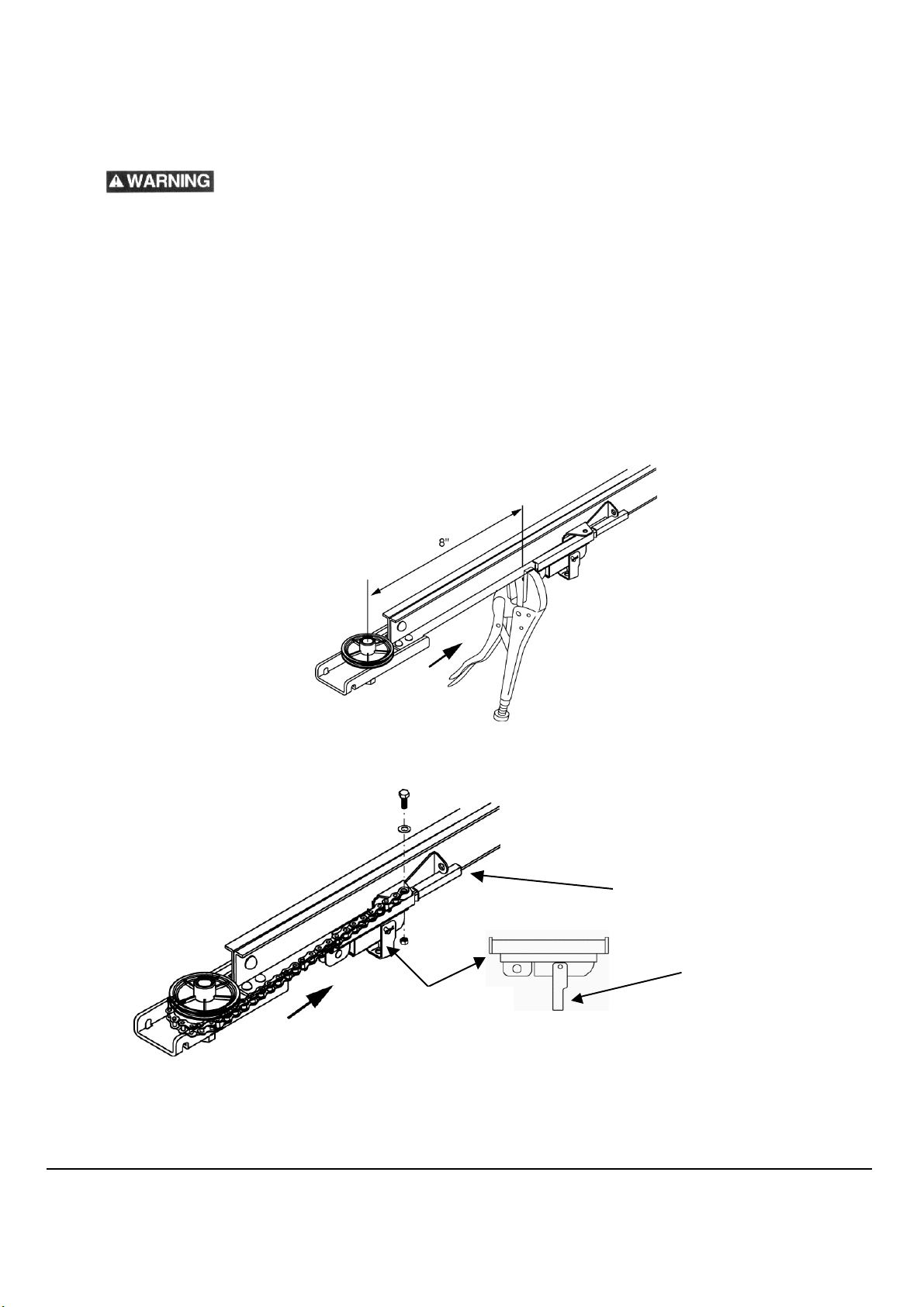
1. Atta ch a p a i r of l ocking p l i ers to the ra il 8 i nches awa y from the center of the gear on the header section
as shown to hold the trolley in position when attaching the chain.
2. Pull the emergency release lever on the Outer Trolley and separate it from the Inner Trolley.
Outer Trolle
Inner Trolley
Emergency Release Lever
a. Connect the end of the chain with the cable loop to the Inner Trolley by placing one washer (∅6-1.5) onto one
(M6-12) bolt, then place the cable loop onto bolt and insert bolt through the mounting hole on the inner trolley
as shown. Thread one (M6) nut onto bolt and tighten. Make sure cable loop is straight when tightening.
9
1/2 HP Chain Drive Garage Door Opener

3. Slide the Inner Trolley and Outer Trolley back together.
4. Attach a pair of locking pliers 8 inches away from the center of the pulley to the rail as shown to keep the
trolley from moving when you attach the chain. Then pull on the cable until the trolley is snug against
the locking pliers:
5. Hold on to the chain and pull the slack out of the cable. Then wrap the chain around the sprocket as
shown:
6.Thread 1 nut (M-8) and place one spring washer (∅8) onto the trolley bolt at the end of the Chain
7.Insert the trolley bolt through the mounting hole as shown, and thread on the second nut (M-8) as shown.
10
1/2 HP Chain Drive Garage Door Opener

8. Adj ust the chain tension by turning the outer nut with a 13mm wrench until the chain is ½ inch away from
the bottom of the rail at the midpoint of the rail. Caution: Use a second wrench to hold the chain from
twisting during assembly.
9. While holding the outer nut in position, tighten the inner nut securely to hold the proper chain tension.
Inner Nut
11
1/2 HP Chain Drive Garage Door Opener

Mounting the Assembled Garage Door Opener
Mounting the assembled garage door opener is done in three main steps:
- Attach the Rail to the Wall
- Attach the Motor Assem bly to the Ceiling
- Attach the Door Brackets to the Garage Door and Garage Door Bracket
Attach the Rail to the Wall – Sectional & One Piece Doors
To avoid injury or death:
- Be su re to securely mount the garage door opener.
- Never touch any moving part while the garage door opener is in operation.
- Do not attempt to fix the garage door opener if it jams or malfunctions. Call a DGO installation professional for
assistance.
1. T h e fi rst step is to d et e rm ine wh e re to a t tach t h e wall b racket. How you do this depends on whether you
have a sectional garage door on rails or a one piece garage door.
If you have a sectional garage door, do the foll owing:
a. Open the door to the highest point of travel. In the center of the wall above the door, draw a
horizontal line 2” above the high point of the garage door. This height will provide travel clearance for
the top edge of the door.
12
1/2 HP Chain Drive Garage Door Opener

If you have a o
ne-piece garage door
, do the following:
a. Open your door to the highest point of travel as shown. Measure the distance from the top of the door to the
floor. Subtract the actual height of the door. Add 8” to the remainder. For example:
91” = Distance from top of door at highest point of travel to floor
87” = Actual height of door
91” – 87” = 4” remainder
4” + 8” = 12”
d. Close the door and draw an intersecting horizontal line on the header wall at the determined height from
the top of the closed door.
13
1/2 HP Chain Drive Garage Door Opener

NOTE: If there is not enough room or if there is no way to secure the garage door opener to the wall
over the spring, you can secure it to the ceiling above the door. Mark the center of the ceiling, no
more than 6 inches from the wall.
2. Mount the Header Bracket with two lag bolts provided to either the wall or the ceiling
OR
14
1/2 HP Chain Drive Garage Door Opener

3. Lay the rail against the wall (or ceiling) mount and rest the motor assembly on something tall such as a ladder
which is enough to support the rail so it does not touch the garage door spring. Some garage doors require this
height to attach the rail to the header bracket. Other doors which do not have the door spring located directly
above the garage door, may allow you to rest the opener on the carton it was shipped in to ease assembly.
4. Then attach the rail front to the wall mount with the Ø8-35mm clevis pin and split pin as shown.
15
1/2 HP Chain Drive Garage Door Opener

Attach the Motor Assembly to Ceiling
To avoid injury or death:
- Be su re to securely mount the garage door opener. Failure to mount the garage door opener securely can result
in damage to property, personal injury and death.
- Never touch any moving part while the garage door opener is in operation.
- Do not attempt to fix the garage door opener if it jams or malfunctions. Call a garage door installation professional
for assistance.
- Do not pl ug in the electrical cord until specifically instructed to do so.
1. While another person steadies the garage door opener, position the hanging brackets on either side of
the motor assembly where they will reach beams in the ceiling overhead. If needed, cut the brackets to
fit. Then attach the brackets with the M8-20 bolts, spring washers and M8 nuts as shown, and
hand-tighten the screws. (Do not securely tighten the screws as you may need to adjust them when
securing the motor to the ceiling in the next step.)
3. Then attach the brackets to the overhead beams with the 2 lag screws.
NOTE: In some cases you may need additional hardware (not included) to secure the garage door.
3. Fi nish ti g h te ni n g t h e screws o n the mo t o r a sse m b l y unti l t h e g a rage door opener is securely mounted.
16
1/2 HP Chain Drive Garage Door Opener

A) Install Safety Sensors and Remote Switches
Installing the door sensors and remotes is done in three main steps:
A) Install the Safety Reversing Sensors
B) Install the Premium Control Console
C) Install the Keyless Entry Control Pad
Install the Safety Reversing Sensors
To avoid injury or death: Be sure to correctly install the safety sensors. Failure to correctly
i nst a l l th e sa f et y se n so rs m ay re su l t i n ma l f un c t io n o f the e m e r ge n c y r eve rse syst em whi ch can result in damage to
property, personal injury and death.
The garage door opener comes with two safety reversing sensors designed to stop the door from closing should
anything be in the way.
NOTES:
-The garage door will not operate unless the safety sensors are installed properly.
-When the invisible beam path is obstructed or misaligned while the door is closing, the door will reverse. If the
door is already open, it will not close. The door opener lights will flash.
Do the following to install the sensors.
1. M ea sure a poin t o n t he ga ra ge do o r whe el tra cks si x i nche s abo ve t he fl oo r whe re the se n so rs will go:
Repeat on the other wheel track.
17
1/2 HP Chain Drive Garage Door Opener

2. To attach the safety sensor bracket, hook the bottom edge of the bracket on the back side of the
wheel track and pull until the bracket snaps onto the track. Then secure the bracket to the rail with the
knobs. Repeat to install the other bracket on the other wheel track.
NOTE: If your garage door is a one-piece door, secure the sensors directly to the wall with two M4-20 screws.
3. Attach each of the two sensors to the sensor bracket using an M5 screw, flat washer, and a wing nut.
Note the “Sending/Transmitting” sensor marked with a “T” and “Receiving” sensor marked with an “R”
for the next step.
18
1/2 HP Chain Drive Garage Door Opener

4. Run the wires back to the garage door motor assembly. Open the side panel on the garage door opener
(
and connect the wires as shown:
Connect black
sending) wire
Connect both
white wires
he re
here
Connect blue
(receiving)
wire here
5. Then secure the wires to the wall and ceiling with the included wire clamps.
6. Finally, make sure the sensors are aligned and in line with each other. Verify alignment by looking at the
green light on the sending/transmitting sensor which will light consistently without flickering when
alignment is achieved.
19
1/2 HP Chain Drive Garage Door Opener

B) Install the Door Be ll
1. Position the control console near the inside door into the garage. Approximately five feet above the
floor to keep out of the reach of small children.
2. Pull the insulation off the ends of the bell wire, then attach the two ends to the back side of the
console as shown.
White (bell wire)
This view is of the back
of the control console
Bell Wire
3. Attach the door bell to the wall with two screws (M4 -20).
NOTE: Do not over-tighten the screw or you could damage the console.
Red (bel l wi re )
20
1/2 HP Chain Drive Garage Door Opener

4. Run the wires back to the garage door motor assembly. Open the side panel and connect as shown:
NOTE: Be sure to connect the wire with the dotted line to…
Connect red
(bell) wire
here
Connect the
white (bell)
wire here
21
1/2 HP Chain Drive Garage Door Opener

C) Install the Keyle ss Entry Control Pad
1. Position the keyless control pad outside of the garage door on the inside door frame and secure with the
two M4-20 screws. NOTE: Be sure the pad is not in the path of the garage door.
2. Remove the lower panel of the keyless control pad, insert the 9V battery, and close the lower panel.
22
1/2 HP Chain Drive Garage Door Opener

Attach the Door Brackets to the Garage Door and Garage Door Bracket
WARNING: To avoid injury or death:
- Be su re to securely mount the garage door opener. Failure to mount the garage door opener properly can result
in damage to property, personal injury and death.
- Never touch any moving part while the garage door opener is in operation.
- Do not attempt to fix the garage door opener if it jams or malfunctions. Call a garage door installation professional
for assistance.
- Do attempt to operate the garage door opener at this time.
- Determine where to attach the door bracket based on your garage door application (one-piece or sectional)
For Se c tiona l Do or s :
1. Mark a continuing centerline on the garage door face as you marked for the header bracket (see Fig. A).
2. Position the door bracket onto the garage door face (note the “UP” position) approximately 2” - 4” below the top
edge of the door, and directly below any structural supports located on the top of the door.
3. Mark and drill (4) 5/16” holes for the door bracket mounting bolts as shown.
4. Place 6 Flat Washers (∅ 10 x 20-2) onto 6 He x Bo l t s (5/16” x 1 8 x 2 -1 /2 ”), insert them through the garage door,
from the outside. Next, place 6 Spring Washers (∅8), and 6 Nuts (5/16”) onto the si x mounting bolts and
tighten.
Fig. A
Sectional Door
23
1/2 HP Chain Drive Garage Door Opener

5. Attach the curved bracket to the door bracket with the clevis pin (Ø8-35) and split pin as shown:
6. Raise the trolley safety release lever to the up/locked position, and slide the outer trolley onto the inner
trolley so they lock into position as shown:
Trolley Safety Release Lever
7. Attach the straight door arm section and attach with clevis pin (Ø8-25) and split pin as shown:
24
1/2 HP Chain Drive Garage Door Opener

8. Bring the straight door arm section and curved door arm section together and secure with two bolts
(M6-45), two spring washers and two nuts (M8):
9. Release/lower the trolley safety release lever into the horizonal position.
10. Feed the free end of the emergency release rope through the end of the trolley safety release lever and
tie a knot in both the ends of the rope. The knob should be at least six feet above the garage floor. Take
the slack out of the rope with an additional knot.
25
1/2 HP Chain Drive Garage Door Opener

For One-Piece Doors:
1. Mark a centerline on the top of the garage door as you marked for the header bracket (see Fig. B).
2. Position and center the door bracket onto the top of the garage door, mark and drill (2) 5/16” holes for the
left and right side of the door bracket (see below).
3. Place 2 Flat Washers (∅10 x 20-2) onto 2 Hex Bolts (5/16” x 18 x 2-1/2”), insert them through the bottom
of the garage, and through the top as shown. Next, place 2 Spring Washers (∅8), and 2 Nuts (5/16”) onto
the four mounting bolts and tighten.
Fig. B
One-Piece Door
26
1/2 HP Chain Drive Garage Door Opener

4. Attach the straight bracket to the curved bracket with the longest possible length, so there is a 3-hole
overlap as shown below. Secure the two sections together with two bolts (M6-45), two spring washers and
two nuts (M8).
5. Fasten the end of the straight arm section to the door bracket using the clevis pin (∅ 8 -35) and split pin as
shown.
Note: Before connecting the door arm to the trolley, you must adj ust the up and dow n travel limits first.
One full turn on the travel adj ustment screws equals approximately 2” of trav el adj ustment. For further
travel limit adjustment description, refer to “Testing & Adj usting the Door Range of Motion” ahead.
Adjusting the UP Travel Limit: (see next page for drawing)
1. Turn the UP travel adjustment screw counterclockwise 5 com plete turns (increasi ng the UP travel limit)
2. Press the door control push button on the Premium Control Console so the trolley will travel to the fully
open position.
3. Manually raise the door to the open position so the door is parallel with the garage floor. If the door has a
downward slope when opened, you have opened the door too far. The end of the curved arm section
should be close to the trolley door arm connector hole.
4. If the arm does not extend far enough to attach to the trolley, adjust the travel limit further.
Adjusting the DOWN Travel Limit: (see next page for drawing)
1. Turn the DOWN travel adjustment screw clockwise 5 complete turns (decreasing the DOWN travel limit)
2. Press the door control push button so the trolley will travel the fully closed position.
3. Manually close the door all the way. The end of the curved arm section should be next to the trolley door
arm connector hole.
4. If the arm does not extend far enough to attach to the trolley, adjust the travel limit further.
27
1/2 HP Chain Drive Garage Door Opener

Fully closed position
Door parallel to the garage floor
Door with a downward slope
Connect the Door Arm to the Trolley:
1. Close the door and connect the end of the curved arm section to the connector hole on the trolley with a
clevis pin (∅ 8-25) and split pin.
2. Run the opener through a complete travel cycle before making any adjustments. If the door has a
downward slope in the full open position as shown above with the dotted line drawing, decrease the UP
limit travel until the door is parallel with your garage floor (see Testing & Adjusting the Door Range of
Motion) on the next page.
28
1/2 HP Chain Drive Garage Door Opener

Testing and Adjusting the Garage Door Opener
Testing and adjusting garage door opener is done in five steps:
A) Adjusting the Chain Tension
B) Testing and Adjusting the Door Range of Motion
C) Testing and Adjusting the Safety Reversing Sensors
D) Testing and Adjusting Door Force
E) Testing and Adjusting the Safety Reverse Feature
A) Adjusting the Chain Te nsion
After you have adjusted the travel distance and force of the garage door opener, verify that the chain tension is still ½
inch away from the bottom of the rail at the chains lowest point.
Note: This is to be tested with the trolley disengaged. (see page 11 for detailed instructions)
B) Testing and Adjusting the Door Range of Motion
This section describes how to adjust the total range of motion for the garage door opener.
Check if Adjustments are Needed
1. Plug in the power cord into an approved power source.
2. Press the Door Control push button. Run the opener through a complete travel cycle.
- Does the door open and close completely?
- Does the door not open or close too far?
- Does the door stay closed and not reverse unintentionally when fully closed?
If your door passes both of these tests, no limit adjustments are necessary. Go to next section on Testing and
Adjusting the Safety Reversing Sensors
29
1/2 HP Chain Drive Garage Door Opener

Adj ust Range of M otion
To avoid injury or death:
- Be sure correctly adjust the door range of motion. Failure to correctly adjust the door range of motion may result
in malfunction of the emergency reverse system, which can result in damage to property, personal injury and
death.
- Do not stand under the garage door opener when adjusting the door range of motion.
If adjustments are needed, follow the adjustment procedures outlined below:
Check each of the following:
1. If the door does not open completely, increase the "up travel" distance by rotating the adjusting screw
clockwise. Locate the two adjustments on the bottom center of the motor housing:
Use a flathead screwdriver to make limit adjustments. Turn the UP limit adjustment screw clockwise as
needed. One full turn equals 2” of travel. Run the opener through a complete travel cycl e after each
adjustment and repeat as needed to fine tune the range of motion.
2. If the door does not close completely, increase "down travel" distance. Turn the down limit adjustment
screw counterclockwise. . Locate the two adjustments on the bottom center of the motor housing:
Use a flat head screwdriver to make limit adjustments. Turn the DOWN limit adjustment screw clockwise
as needed. One full turn equals 2” of travel. Run the opener through a complete travel cycle after each
adjustment and repeat as needed to fine tune the range of motion.
3. If the opener reverses when it reaches its fully closed position, decrease down travel by adjusting the
downward travel limit screw clockwise.
4. If the door reverses when closing and there is no visible interference to the travel cycle, check the door
for binding. Pull the trolley emergency release handle and manually open and close the door. If the door
is binding or unbalanced, call a trained garage door technician. If the door is not binding or unbalanced,
adjust the Down force. See next section:
30
1/2 HP Chain Drive Garage Door Opener

C) Testing and Adjusting the Safety Reversing Sensors
To avoid injury or death:
- Do not stand under the garage door opener when testing the safety sensors.
- Do not operate the garage door opener if the safety sensors are not working properly.
1. Press the remote control push button to open the door.
2. Place an empty cardboard box carton in the path of the door.
3. Press the remote control push button to close the door. The door should not move. If it does, contact
technical support for instructions.
4. Re m ove the box a n d p ress the re m ote con trol p u sh b u t ton to cl ose th e door. Place the box in the door's
path. The door should automatically reverse. If it doesn't, contact technical support for instructions.
D) Testing and Adjusting Door Force
To avoid injury or death:
- Be sure correctly adjust the door force controls. Failure to correctly adjust the door force controls may result in
malfunction of the emergency reverse system, which can result in damage to property, personal injury and death.
- Do not stand under the garage door opener when adjusting the door force controls.
- After any adjustments are made, test the safety reversal syst e m .
Force adjustment settings regulate the amount of power required to open and close the door. If the force adjustment is
set too light, door travel may be interrupted in the down direction and stops in the up direction. If it is set too heavy, the
door will not emergency reverse fast enough.
Weather conditions can affect the door movement, so occasional adjustment may be needed.
1. Locate the force adjustment controls on the side panel of the motor unit.
31
1/2 HP Chain Drive Garage Door Opener

The maximum force adjustment range is about ¾ of a complete turn. Do not force controls beyond that
point. Turn force adjustment controls with a screwdriver.
2. Test th e DOWN (cl o se) force. G rasp the door b o ttom wh en th e do or is about halfway through DOWN
(close) travel and try to stop the door. The door should reverse. If the door is hard to hold or doesn’t
reverse, DECREASE the DOWN (close) force by turning the control clockwise. Make small
adj u stm ents un ti l t h e d o or c o m pl ete s a close c ycl e . After each adjustment, run the opener through a
com plete trave l cycl e . Do n o t i ncre a se the fo rce beyond th e m inimum amount required to close the
door.
3. Test th e UP (open) force. If the door does not open ful l y INCREASE UP (Open) force by turning the
control clockwise. Make small adjustments until door opens completely. Readjust the UP limit if
necessary. After each adjustment, run the opener through a complete travel cycle.
E) Testing and Adjusting the Safety Reverse Feature
To avoid injury or death:
- Be sure correctly adjust the safety reversal system. Failure to correctly adjust the door force controls may result in
malfunction of the emergency reverse system, which can result in damage to property, personal injury and death.
- Do not stand under the garage door opener when adjusting the safety reversal system.
Your Garage Door Opener comes with a safety feature that makes the door automatically reverse if the door
encounters an object before it fully closes.
1. With the door fully open, place a one-inch board (or a 2x4 laid flat) on the floor, cenetered under the
garage door. Operate the door in the down direction. The door must reverse on striking the obstruction.
2. If the door stops shy of the obstruction, it is not traveling far enough in the down direction. Increase the
DO WN li m it by turn i ng t h e DOWN l imi t a d j ustm e n t screw countercl ockwise ¼ turn. Repeat until it hits the
board and reverses.
3. If the door stops on the obstruction but does not reverse, reduce the DOWN force by turning the
adjustment screw counterclockwise ¼ turn. Repeat until it automatically reverses when it hits the board.
32
1/2 HP Chain Drive Garage Door Opener

utto
cato
Programming the Remote Controls
Your garage door opener has already been programmed at the factory to operate with your hand-held remote control.
The door will open and close when you press the first push button.
Below are instructions for programming your opener to operate with additional remote controls.
Programming Remote Control
Using the "Learn" Button on the Garage Door Opener
1. Press and release the “learn” button on the motor unit. The learn indicator light and warning light will glow
st e adi l y fo r 30 se c o nd s.
Learn
Button
Learn B
2. Within 30 seconds, press all three push buttons on the remote control then release the buttons. Note:
learn indicator light will flash slowly.
3. Within 30 seconds, press and hold the button on the handheld remote that you wish to operate your
garage door for 3 seconds and release. Note: Learn indicator light will blink rapidly and stop.
n Indi
r Light
Erasing All Codes From Garage Door Opener M emory
To d eactiva te an y u n wanted remotes, first erase all co de s. Push the Lea rn button and hold for a pp roxima tel y 6 second s.
All previous codes are now erased.
Reprogram each remote or Keyless entry you wish to use.
Adding or Changing a Keyless Entry Code
The keyless entry control panel and garage door opener must be programmed with a code in order to operate your
garage door opener with the keyless entry.
33
1/2 HP Chain Drive Garage Door Opener

Adding a New Code
Using the "Learn" Button on the Garage Door Opener
1. Press and release the “learn” button on motor unit. The learn indicator light and warning light will glow
st e adi l y fo r 30 se c o nd s
2. Within 30 seconds, enter a four digit personal identification number (PIN) of your choice on the keypad.
Then press and hold the ENTER button for 3 seconds.
3. T h e learn i n di cator li gh t wil l f l a sh rapi d l y and the warn ing li g h t will flash 3 times. Your Wireless Keypad
has now learned the code.
4. Test by pressing the new PIN, then press Enter. The garage door opener should operate.
To Change an Existing Code
If the existing code is known, it may be changed by using the Keyless Entry.
1. Enter the four buttons for the present PIN, then press and hold the # button. The warning light will glow
steadily. Release the # button.
2. Within 15 seconds, press the new 4-digit code you have chosen, then press and hold Enter for 3
seconds. The warning light will blink twice, then blink rapidly and stop. The new code is now
programmed.
3. Test by pressing the new PIN, then press Enter. The garage door opener should operate.
To Add a Guest Entry (Temporary) PIN
A Guest Entry PIN can be added to your Keyless Entry Pad which allows you to authorize access by visitors or service
people by addiding a temporary 4 digit PIN.
1. Press the 4 buttons for your personal entry Master PIN, then press and hold the * button until the warning light
stays on.
2. Within 15 seconds, press the 4 buttons for your personal Guest Entry PIN (can not set as 0000), then press
and hold the ENTER button.
3. The warning light will blink twice when the Guest Entry PIN has been added successfully. If you input an
incorrect code more than ten times continuously, the Keyless Entry Pad would stop working for fifteen minutes.
During the fifteen-minute pause, the warning light will blink consistently. However, you can use the Hand-Held
Remote or the Control Console to recall the Keyless Entry to work.
To Erase a Guest Entry (Temporary) PIN
1. Press the 4 buttons for your personal entry Master PIN, then press and hold the * button until the warning light
stays on.
2. Within 15 seconds, enter 0000, press and hold the ENTER button.
3. The warning light will blink twice when the Guest Entry PIN has been erased successfully.
34
1/2 HP Chain Drive Garage Door Opener

Using Your Garage Door Opener
To avoid injury or death:
- Never permit children to operate the garage door opener.
- Make sure the area is clear under the door before operating.
- Do not attempted to operate a jammed garage door opener. Consult a garage door opener professional for
assistance.
- Do not attempted to repair a jammed garage door opener. Consult a garage door opener professional for
assistance.
Be sure to unplug the garage door opener from the electrical source before making any adjustments.
Opening/Closing the Garage Door
Use any of the following to open or close the garage door:
The hand-held remote control: Hold the dedicated button down until the door starts to move.
The door bell: Press the lighted push button to open or close the door. Press again to reverse
the door during the closing cycle or to stop the door while it’s opening.
The keyless entry pad: Enter the code you programmed into it to activate the door.
Locking Out the Hand-held Remote Controls
You can lock out the hand-held remote controls so the door can only be operated from the wall-mounted control.
- To activate the Lock feature, press and hold the Lock button for 1 second. The light will flash as long as the Lock
feature is on.
- To turn off, press and hold the Lock button for 1 second. The push button light will stop flashing.
To Open the Door M anually
To open the door manually, pull the emergency release handle and lift the door manually.
To recon nect the trolley, re turn the em erg ency rel ease arm to i ts origi n al horizontal position. The trolley will re-engage
the next time you operate the garage door opener.
35
1/2 HP Chain Drive Garage Door Opener

Caring for your Garage Door Opener
Maintaining the Ope ne r
Do the following to maintain your garage door opener:
Monthly: Once a month, test that the garage door opener opens and closes properly as seasonal weather
change may affect the garage door and garage door opener. If needed, adjust the range of
motion and force setting per the instructions on pages 30-31.
Cha nging Re mote Contr ol Ba tte ry
Re m ote Co nt r ol
To replace the battery in the remote control:
1. Use a flathead screwdriver blade at the bottom of the remote to pry open the case.
2. Take out old battery and Insert a new 23A – 12V battery positive side up as shown.
3. Replace the cover and dispose of the old battery properly.
Keyless Entry Control Pad:
To replace the battery in the keyless entry pad:
1. Remove the lower panel of the keyless entry pad:
2. Take out old battery and dispose of properly.
3. Insert new 9V battery.
4. Close the lower panel.
36
1/2 HP Chain Drive Garage Door Opener

Homelink Programming
HomeLink is an integrated transceiver (a transmitter and receiver) that can be programmed to activate your garage
door opener. HomeLink can be found on over 140 different vehicle models (see your vehicle’s owners manual for
detailed information).
If your Motor Vehicle is equipped with HomeLink, please follow the below instructions to program:
1. For first time programming with a garage door opener, press and hold all 3 HomeLink buttons for approximately
one minute, releasing only when the HomeLink indicator light turns off. (Do not perform this step when
programming the additional HomeLink buttons)
2. To ensure HomeLink is in the proper training mode, press and hold each of the buttons individually. When
pre ssed, the in d i vi d ua l Hom eL i nk butto n sh ou l d m ake the i nd i ca tor l i g ht b li nk rap i dly f o r 2 seconds and then
turn a solid/continuous light.
A second person may make the following steps quicker & easier. As a safety precaution, DO NOT stand on your
vehicle. Use a stepladder or other stable, safe device.
3. At the garage door opener receiver (motorhead unit) in the garage, locate the training button (usually near
where the hanging antenna wire is attached to the unit). If there is difficulty locating the training button, please
reference the garage door opener’s manual, visit their website www.homelink.com
4. Press and release the training button (which activates the “training” light) NOTE: Once the button is pressed,
there are 30 seconds in which to initiate the next step.
5. Return to the vehicle and firmly press and hold the desired HomeLink button to be programmed for two
seconds and release. Repeat the “press/hold/release” a second time to activate the door. (You may need to
repeat this sequence up to 3 times to complete the training process).
HomeLink should now activate your rolling code equipped opener.
Once programmed, the HomeLink Wireless Control System or the original hand held transmitter may be used to
activate this garage door opener. In the event there are still programming difficulties, please contact HomeLink at
1-800-355-3515 or visit their website at www.homelink.com.
It is recommended that upon sale of the vehicle, the programmed HomeLink Wireless Control System buttons be
erased for security purposes. To erase the programmed HomeLink buttons, press and hold the two outer
o r ca l l at 1 -800-355-3515.
HomeLink buttons until the indicator light begins to flash after about 20 seconds.
37
1/2 HP Chain Drive Garage Door Opener

Homelink Accessories
If you would like additional information on the HomeLink® Wireless Control System, HomeLink compatible products,
programming instructions for other devices or to purchase accessories, please contact HomeLink at
1-800-355-3515 or visit their website at www.homelink.com
Precautions!
Do not use the HomeLink® Wireless Control System with any garage door opener that lacks the safety stop and
reverse feature as required by federal safety standards. (This includes any garage door opener model
manufactured before April 1, 1982). A garage door opener that cannot detect an object, signaling the door to stop
and reverse, does not meet current federal safety standards. Using a garage door opener without these features
increases risk of serious injury or death. For more information, call 1-800-355-3515 or visit their website at
www. h o me l i n k. c om
This device complies with FCC rules part 15. Operation is subject to the following two conditions: (1) This device
may not cause harmful interference, and (2) This device must accept any interference that may be received
including interference that may cause undesired operation. WARNING: The transmitter has been tested and
complies with FCC and IC rules. Changes or modifications not expressly approved by the party responsible for
compliance could void the user’s authority to operate the device.
Th e t e rm “IC:” before the ce rti fi ca ti o n /reg i stration n u m ber only signi f i e s t h a t Industry Canada technical specifications
we r e m e t.
.
.
IC: 279B-xxxxx JCI MODEL/FCC ID: CB2XXXXX
HomeLink and the HomeLink house are registered trademarks of Johnson Controls, Inc.
38
1/2 HP Chain Drive Garage Door Opener

Tr oubleshoot ing
Use the following table to troubleshoot common problems with the garage door opener. If the following does not
resolve the problem, contact technial support or a professional garage door opener repairman.
Symptom Possible Cause Solution
The garage door opener starts to
operate but then stops
immedately.
The range of motion setting is
The force setting is incorrect. Adjust the force setting per the
The safety reverse setting is
The springs may be old and weak
The garage door opener w ill not
operate at all and the light will not
turn on.
The plug the opener is plugged into
The garage door is locked. Unlock the door and try again.
Adjust the setting per the instructions
incorrect
incorrect
requiring more force to open the
door than the opener can provide.
The opener is not plugged in. Plug the opener into 110v power
has no power.
on page 29.
instructions on page 31.
Adjust the setting per the instructions
on page 32.
Replace the old and weak springs.
outlet.
Check the circuit breaker.
The garage door opener w ill not
operate at all but the light will turn
on.
The wires from the safety sensors
An object is blocking the safety
The garage door opener does not
open fully or close fully.
The range of motion setting is
The force setting is incorrect. Adjust the force setting per the
The safety reverse setting is
39
T h e safety se n sors are not ali gned. A l ign the senso rs per the di re ctions
on page 17.
Verify the wires are correctly
are broken or not connected.
sensors.
Something is blocking the garage
door.
incorrect
incorrect
attached to the opener per the
instructions on page 17.
Check that nothing is blocking the
line-of-site between the two safety
sensors. If so, remove it.
Remove the obstruction.
Adjust the setting per the instructions
on page 29.
instructions on page 31.
Adjust the setting per the instructions
on page 32.
1/2 HP Chain Drive Garage Door Opener

Symptom Possible Cause Solution
The garage door opener w ill not
open using the remote control.
The battery in the control panel is
dead.
T h e remo te co n t ro l has not yet been
programmed.
The remote controls have been
locked out.
All codes have been erased from the
opener.
The garage door opener w ill not
open using the keyless entry
The battery in the control panel is
dead.
control panel.
The keyless entry code has not yet
been programmed.
The remote controls have been
locked out.
All codes have been erased from the
opener.
Replace the batteries per the
instructions on page 36.
Program the remote control per the
instructions on page 33.
Unlock the remote controls per the
instructions on page 35.
Reprogram the remote control per
the instructions on page 33.
Replace the batteries per the
instructions on page 36.
Prog ram th e ke yl e ss ent ry co de per
the instructions on page 33.
Unlock the remote controls per the
instructions on page 35.
Prog ram th e ke yl e ss ent ry co de per
the instructions on page 33.
The garage door opener operates
but the door does n’t move.
The chain droops or makes a
scraping noise.
T h e e m ergency re lease h andle has
been pulled.
The chain tention is not adjusted
properly.
Return the emergency release arm
to its origin a l ho rizontal position. The
trolley will re-engage the next time
yo u o perate t he g a ra ge door opener.
Adjust the chain per the instructions
on page 11
40
1/2 HP Chain Drive Garage Door Opener

Parts List and Schematic Diagrams
When servicing use only authorized replacement parts. Use of any other parts may create a
HAZARD or cause product damage.
Any attempt to repair or replace electrical parts on this garage door opener may create a
HAZARD unless repair is done by a qualified service technician.
No te : Always order parts by I.D. Number.
Parts List: Schematic A – Rail Assembly and Other Parts
I.D. No. Descrip tion S ize Qty I.D. No. Description Size Qty
2384 SPRI N G PLATE 2 0K D1 H EXAG ON W ASH ER H EAD TAPP I NG 5/16x9U NC -1 5/8 2
2385 TR OLL EY 1 0K D1 H EXAG ON W ASH ER H EAD TAPP I NG 5/16x9U NC -1 5/8 2
2386 TR OLL EY 1 0K HX C AP HD. SQ . NEC K BO L T M 5X0.8-10 2
07TQ SU PPO RT 1 0 K M Y H E X . N U T M 8 x 1. 2 5 ,T= 6. 5 2
07TR LI NK BAR 1 0 K M Y H E X . N U T M 8 x 1. 2 5 ,T= 6. 5 2
07TS LI NK BAR 1 0K PP H EX. NU T 5/16x18U NC T=6.7 6
07TW HAND LE 23# 1 0K Q8 W I N G NU T M 5x0.8 2
07TX ROP E 1 0K QX N U T CH U C K M 6x 1.0 T= 6 4
07TY DRAW BAR 1 0K QX N U T CH U C K M 6x1.0 T=6 2
07TZ COM PRESSI ON SPRING
07U 0 LOC ATI N G B AR 1 0K R4 N U T CH U CK M 8x 1.25 T= 8 4
07U 2 DAM P ER 6# 1 0LNS B ATTER Y 1
07 U A SE T P L AT E 2 0 X G V P I N φ4-30 1
07VM LEAD W I RE ASS 'Y 1 0XH5 P I N φ8-16 1
0C P0 CLAM P B OLT 6# 2 0XH6 P I N φ8-25 1
0J4D FLAT W ASHER φ5x 10⁻¹ 2 0XH7 P I N φ8-65 1
0J4U FLAT W ASHER φ6x 18- 1. 5 1 0XH8 ANF TY P E NAI L FI XED C LI P 15
0J50 FL AT W ASHER φ6. 3x 15-4 2 20ZU TO RS IO N SP RI NG 1
0J6G FLAT W ASHER φ8. 2x 18- 2. 0 6 214Y H EX. H D . B O L T 5/16"-18UNC-2 1/2" 6
0J87 FLAT W ASHER 8#x1/2-3/64 2 23AE GU I DE H O LDER 6# 2
0J94 SPRI NG W ASH ER φ8 2 23B2 C AP HD. SQ. NECK B OL T M 6x 1.0- 16 4
0J94 SPRI NG W ASH ER φ8 1 23BF C ONTROL LER ASS ' Y 1
0J94 SPRI NG W ASH ER φ8 3 23BG CONTRO L LER AS S' Y 1
0J9D SPR I N G W ASHER φ8 4 23BN C ONTRO L LER ASS 'Y BP # 1
0J9D SPR I N G W ASHER φ8 6 23BT C O NTRO LL ER AS S' Y 1
0JD T SPL I T P I N φ8- 27. 7 2 23C8 C O NTROLL ER ASS' Y 1
0JD T SPL I T P I N φ8- 27. 7 1 23KH RETAINI NG C L IP 2
0JP 4 HEX . H D . BOL T M 8x 1. 25-16 3 23LE C ONTROL L ER AS S' Y 1
0JP C HEX . H D. BOL T M 6x 1. 0- 12 1 24HQ S U P POR T 1
0JP D HEX. H D. BOLT M 6x1. 0-16 2 27A9 RAI L 1
0JP U HEX . H D . BOL T M 8x 1. 25-20 2 27AS W H EEL ASS'Y 1
0JR E HEX . H D . BOL T M 8x 1. 25-40 4 27AV CH AIN ASS 'Y 1
0K 90 CR . R E. TRU SS H D. TAPP I NG SCR EW M 3. 5x18-16 2
0K C7 CR. RE. TRU SS HD. TAPPING SCREW M 4x16-10 2
1 0K QX NU T CH U C K M 6x 1.0 T= 6 1
41
1/2 HP Chain Drive Garage Door Opener

Schematic A – Rail Assembly and Other Parts
42
1/2 HP Chain Drive Garage Door Opener

Parts List: Schematic B – Motor Assembly
I.D. No. Description Size Qty I.D. No. Description Size Qty
2104 FLAT W ASHER 1 0K FF C R. RE. P AN H D. SC REW M 5x0. 8-8 1
2236 SET PL ATE 1 0K H X C AP HD . SQ. NEC K BO L T M 5X0.8-10 1
2237 SET PL ATE 2 0K R L U - TY PE NU T M 5- 12 2
2238 SET P L ATE
07U K W ORM 1 0K R Y H EXAGON NU T AND FLAT W ASH ER M 5x 0. 8 3
07U M BU SH
07U N BU SH
07U P SPRI NG CAP
07U Q PARRLE RING
07U R INTERRU PER CU P 6# 1 0Q 98 M OTOR 1
07U S SP EED SEAT 6# 1 0S H E W ORM GEAR ASS ' Y 1
07U T CO NTR OLL ER 1 0XGY CAPAC I TOR SET PL ATE 1
07U Z CO VER 6# 1 0X GZ C AP AC I TOR ASS 'Y 1
07V2 LAM P S OCK ET 6# 1 0X H 0 L EAD W I RE ASS' Y 1
07V3 SI DE C O VER 6# 1 20ZT AXL E SEAT AS S' Y. 1
07V4 BASE 1 20ZU TO RSION SPR I NG
07VE CAPACI TOR ASS' Y 1 214E C AU TI ON L ABEL 1
07VF TERM I NAL ASS 'Y
07VN RETAI N I N G C L I P 1 22C S M O TOR BR ACKET 1
0J AF EX TE R N AL T O O TH L OC K W ASH ER φ5 1 22C T L ABEL 1
0JB 3 W AVE W AS H ER W W - 14 1 22C U LAB EL 1
0JC H SPR I NG PI N 5-20 1 22D Q L EAD W I RE ASS'Y 1
0JX7 HEX. SOC. SET SC REW M 6x1.0-6 2 22Q E C R. RE. RO U N D W ASH ER H D. SCREW M 5x 0. 8- 16 2
0K 6X CR . - RE. TRU SS H D. SCREW M 4x0. 7-6 1 22Q F C R . RE. TRU SS HD. TAP P ING SC R EW M 5x 12-20 1
0K 7F CR. RE. ROU ND WASHER HD. SCREW M 5x0.8-8 1 22QJ C O NTROLL ER AS S' Y 1
0K 7F CR. RE. ROU ND WASHER HD. SCREW M 5x0.8-8 1 22YU SH AFT S LEEVE 1
0K 7F CR. RE. ROU ND WASHER HD. SCREW M 5x0.8-8 3 23B C SAND ER B P C olor 1
0K 7F CR. RE. ROU ND WASHER HD. SCREW M 5x0.8-8 4 23B Y L EN S AS S' Y 1
0K 7F CR. RE. ROU ND WASHER HD. SCREW M 5x0.8-8 4 23Q3 TR ADE-M ARK LAB EL 2
0K 7F CR. RE. ROU ND WASHER HD. SCREW M 5x0.8-8 4 23U C LAM P LABEL 1
0K 7G CR. RE. ROU ND W ASHER HD. SCREW M 5x0.8-12 6 23U D L EARNI N G L ABEL 1
0K 91 CR . R E. TRU SS H D. TAPP I NG SCR EW M 4x16- 12 1 23U Q C ONNEC T W I RE L ABEL 1
0K 94 CR . R E. TRU SS H D. TAPP I NG SCR EW M 5x12- 16 1 23U W TO RSION ADJU ST L ABEL 1
0K A9 CR. RE. PAN H D. TAPPI NG SCR EW M 3x24-10 4 24AV L I GH T R EF LEC TIO N P LATE
0K B4 CR . RE. P AN HD. TAPP I NG SCREW M 4x18-12 2 24F 8 L AB EL 1
2 0K RP SER R AT ED T OOT H ED H EX AGON F LANGE NUT
1 0K TH S TRAI N RELI EF 1
1 0L8X P OW ER C ABL E 1
1 0L M H L OC KI NG C ABLE TI E 2
1 0LNN C OR D C L AM P
1 21QT S I D E COVER 6# 1
M5x0.8,T=5
1
2
1
1
43
1/2 HP Chain Drive Garage Door Opener

Schematic B – Motor Assembly
44
1/2 HP Chain Drive Garage Door Opener
 Loading...