

Revolabs 01-EWM5-DR-BNI, 01-EWM5-DR-WHT, 01-EWM5-OM-BLK, 01-EWM5-OM-WHT, 01-EWM5-OM-BNI Installation And Operation Manual
...Page 1
™
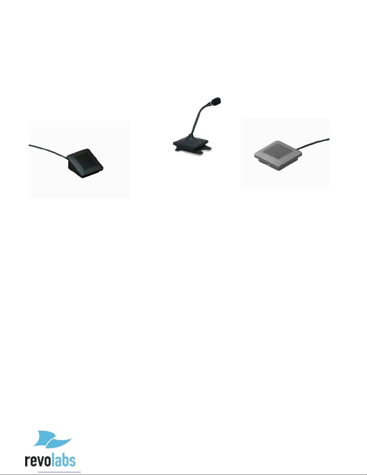
REVOLABS Elite
Wired Microphones
Installation and Operation Guide
Models:
01-EWM5-DR-BLK 01-EWM5-DR-WHT 01-EWM5-DR-BNI
01-EWM5-OM-BLK 01-EWM5-OM-WHT 01-EWM5-OM-BNI
01-EWM5-GN6-BLK 01-EWM5-GN6-WHT 01-EWM5-GN6-BNI
01-EWM5-GN12-BLK 01-EWM5-GN12-WHT 01-EWM5-GN12-BNI
Page 2

2
© 2015 REVOLABS, INC. All rights reserved. No part of this document may be
reproduced in any form or by any means without express written permission from
Revolabs, Inc. Product specifications are subject to change without notice.
Revolabs Eilte Wired Microphone Installation and Operation Guide
10- EXECWM5GUIDE- EN
June 2015 (Rev 1.0.0)
Page 3

3
Introduction
Congratulations on your purchase of the Revolabs Elite™ Wired Microphone
with Mute control and indicator light. This microphone utilizes state of the art
technology providing high bandwidth audio and enabling clear, reliable audio
capture for your applications.
Please read this documentation carefully and follow the instructions before
installing and using your Elite™ Wired Microphone.
Page 4

4
Safety and General Information
Please read the following information to ensure safe and efficient use of your Revolabs
system.
FCC Notice to Users
This device complies with Part 15 of the FCC Rules. Operation is subject to the
following two conditions: (1) this device may not cause harmful interference,
and (2) this device must accept any interference received, including
interference that may cause undesired operation.
Users are not permitted to make changes or modify the equipment in any way.
Changes or modifications not expressly approved by Revolabs, Inc. could void
your authority to operate this equipment under Federal Communications
Commission’s rules.
RADIO AND TELEVISION INTERFERENCE
This equipment has been tested and found to comply with the limits for a Class
B digital device, pursuant to Part 15 of the FCC rules. These limits are
designed to provide reasonable protection against harmful interference in a
residential installation. This equipment generates, uses and can radiate radio
frequency energy and, if not installed and used in accordance with the
instructions, may cause harmful interference to radio communications.
However, there is no guarantee that interference will not occur in a particular
installation. If this equipment does cause harmful interference to radio or
television reception, which can be determined by turning the equipment off and
on, the user is encouraged to try to correct the interference by one or more of
the following measures:
- Reorient or relocate the receiving antenna.
- Increase the separation between the equipment and the receiver.
- Connect the equipment into an outlet on a circuit different from that to
which the receiver is connected.
- Consult the dealer or an experienced radio/TV technician for help.
You may also find helpful the following booklet, prepared by the FCC: "How to
Identify and Resolve Radio-TV Interference Problems." This booklet is available
from the U.S. Government Printing Office, Washington D.C. 20402
Page 5
5
Industry Canada Notice to Users
Model Number:
Description:
01-EWM5-DR
Elite Wired Directional Microphone with Mute Control and
Indicator
01-EWM5-OM
Elite Wired Omnidirectional Microphone with Mute Control and
Indicator
01-EWM5-GN6
Elite Wired Gooseneck Microphone with Mute Control and
Indicator, 15 cm
01-EWM5-GN12
Elite Wired Gooseneck Microphone with Mute Control and
Indicator, 30 cm
Operation is subject to the following two conditions:
(1) This device may not cause interference and
(2) This device must accept any interference, including interference that may
cause undesired operation of the device
Le présent appareil est conforme aux CNR d'Industrie Canada applicables aux
appareils radio exempts de licence. L'exploitation est autorisée aux deux
conditions suivantes : (1) l'appareil ne doit pas produire de brouillage, et (2)
l'utilisateur de l'appareil doit accepter tout brouillage radioélectrique subi,
même si le brouillage est susceptible d'en compromettre le fonctionnement.
Notice to European Customers
Revolabs, Inc.
190, High Street,
Tonbridge, Kent,
TN9 1BE,
UK.
Declare that for the hereinafter mentioned product model numbers, the
presumption of conformity with the applicable essential requirements has been
approved in accordance with the Electromagnetic Compatibility (EMC) Directive
2004/108/EC, and RoHS II Directive 2011/65/EU.
Any unauthorized modification of the products voids this Declaration.
For a copy of the original signed declaration of conformity, please contact
Revolabs at the above address.
Page 6

6
WEEE Notification
The Waste Electrical and Electronic Equipment (WEEE) directive (2012/19/EU)
is intended to promote recycling of electrical and electronic equipment and
their components at end of life.
According to the requirement of the WEEE legislation the following user
information is provided to customers for all branded Revolabs products subject
to the WEEE directive.
“The symbol on the product or its packaging indicates that this product must
not be disposed of with your other household waste. Instead, it is your
responsibility to dispose of your waste equipment by handing it over to a
designated collection point for the recycling of waste electrical and electronic
equipment. The separate collection and recycling of your waste equipment at
the time of disposal will help conserve natural resources and ensure that it is
recycled in a manner that protects human health and the environment. For
more information about where you can drop off your waste for recycling, please
contact your local authority, or where you purchased your product.”
Safety Warnings
• Follow the instructions in the Revolabs Elite Wired Microphone Installation
and Operation Guide.
• Do not expose any of the Elite Wired Microphones to water, moisture, or
high humidity.
• Do not expose any of the Elite Wired Microphones to extreme high or low
temperatures.
• Do not expose any of the Elite Wired Microphones to lit candles, cigarettes,
cigars, or to open flames, etc.
• Do not drop, throw, or try to bend the microphones, as rough treatment
could damage them.
• Do not open the casings of any of the Elite Wired Microphones.
• Do not use any other accessories than Revolabs’ originals intended for use
with this product. Use of non-original accessories may result in loss of
performance, damage to the product, fire, electric shock or injury. The
warranty does not cover product failures which have been caused by use
of non-original accessories.
Page 7

7
Content
Introduction ............................................................................................................................................ 3
Safety and General Information ....................................................................................................... 4
FCC Notice to Users ........................................................................................................................................... 4
Industry Canada Notice to Users ................................................................................................................. 5
Notice to European Customers..................................................................................................................... 5
WEEE Notification ............................................................................................................................................. 6
Safety Warnings ..................................................................................................................................... 6
Content ...................................................................................................................................................... 7
Components ............................................................................................................................................ 8
Installation .............................................................................................................................................. 9
Dip switch Settings ........................................................................................................................................... 9
Audio wire connection ................................................................................................................................. 11
Control Wire Connection ............................................................................................................................. 12
Microphones ......................................................................................................................................... 12
The Elite Omni-Directional Wired Tabletop Boundary Microphones ........................................ 12
The Elite Directional Wired Tabletop Boundary Microphones .................................................... 14
The Elite Gooseneck Tabletop Microphones ....................................................................................... 15
Warranty ................................................................................................................................................ 15
Technical Support ............................................................................................................................... 16
Specifications ........................................................................................................................................ 16
Page 8

8
Components
Your Revolabs Elite Wired Microphone comes with a 15’ (4.5 m) cable attached
to connect it to a phantom powered microphone input of a digital signal
processor (DSP), or other audio devices. The packaging includes the
microphone with cable and a short installation documentation.
The Revolabs Elite system is designed to optimize audio capture by providing
consistent and high-level audio input from all participants.
You might have purchased additional components like the installation kit to
install your microphones permanently. Please review the documentation of
these components for their installation information.
Page 9

9
Installation
The Elite Wired Microphones with Mute Control and Indicator are equipped
with a 15’ (4.5 meter) cable that allows integration with audio equipment. If
the microphone mute is controlled locally, only the audio wires (mic positive
(red), mic negative (black), and ground) need to be conneted to the audio
equipment.
If external mute control is being implemented, and the LED indicator on the
microphone is controlled externally, the switch out (green), LED in (blue) and
I/O ground cables also need to be connected to the GPIO ports controlling the
behavior.
Dip switch Settings
The DIP switches manage the behavior of the mute
control (mute button) and the LED indicator light on
the microphone. The switches are located on the
bottom of the microphone and numbered 1 thorugh
6.
To access the DIP switches, remove the bottom door of
the microphone using a screwdriver or similar tool to
press on the latch and then remove the door. Set the
DIP switches based on the following tables to achieve
the intended behavior.
Page 10

10
External Control
Switch Position
Mode
1 2 3 4 5
6
External Control
LED
ON
OFF
OFF
OFF
OFF
OFF
External Control
Red LED
ON
ON
OFF
OFF
OFF
OFF
Switch Position
Mode
1 2 3 4 5
6
Local Control, Push to
Talk
OFF
ON
ON
OFF
OFF
OFF
Local Control, Push to
Mute
OFF
ON
OFF
ON
OFF
OFF
Local Control, Mute
Toggle, start muted
OFF
ON
OFF
OFF
ON
OFF
Local Control, Mute
Toggle, start unmuted
OFF
ON
OFF
OFF
OFF
ON
Microphone is always on
(no mute functionality)
OFF
ON
OFF
OFF
OFF
OFF
When external Control is desired, DIP switch One needs to be in the ON
position.
Enabled, >2.8V in = Red
LED , <2.4V in = Green
Enabled, >2.8V in =
Green LED , <2.4V in =
DIP switches 3 – 6 should be in the OFF position. If any of these DIP switch is
set to ON, local control of the mute functionality will be enabled, causing
unwanted and unpredictable microphone mute behavior and might lead to
audio distortions.
Local Mute Control
To enable local mute control (and disable the Switch Out wire and LED In
wire), DIP switch One needs to be in the OFF position.
DIP switch 2 should be in the ON position – the LED will show green when the
microphone is unmuted, red when it is muted. If DIP switch 2 is in the OFF
position, the LED behavior will be oposit (green when muted, red when
unmuted).
Only one of the DIP switches 3 through 6 should be in the ON position, the
others should be in the OFF position, depending on the mute behavior desired.
Page 11

11
If more than one of the DIP switches 3 – 6 is in the ON position, unwanted and
Switch Position
Mode
1 2 3 4 5
6
Local Control, Mute
Toggle, start unmuted
OFF
ON
OFF
OFF
OFF
ON
unpredictable microphone mute behavior will be observed and audio
distortions will be experienced.
In Push to Mute mode, the microphone send audio data, unless the button is
pressed, at which time the microphone will mute.
In Push to Talk mode, the microphone is muted, unless the user presses the
button, at which time the microphone sends audio data until the button is
released again.
In Toggle mode, the microphone is muted or unmuted, changing its state each
time the button is pressed.
Factory preset
Factory preset for the DIP switches is on local control, red LED light indicates
mute, mute toggle starting unmuted.
Audio wire connection
Connect the red wire to the positive (+) microphone input of the DSP or audio
equipment you use with the microphone. Similarly, connect the black wire
with the negative (-) input of the DSP. When connecting to a male XLR
connector, use the following polarity:
1 – Ground / Shield
2 – Positive (+)
3 – Negative (-)
Page 12

12
Note: The Elite Wired Microphone includes some active electronic
circuitry, and therefore requires Phantom Power to be provided
from the device the microphone is connected to. The Elite Wired
Microphone requires a phantom voltage between 12 and 48V DC,
with a draw of maximum 2mA.
Control Wire Connection
The Control wires will be connected with the GPIO ports of the DSP or other
technology that is controlling the mute status of the microphones. The control
wires are only used when external control is selected using the DIP switches.
Using external control, pressing the button on the microphone will pull the
switch out line to ground. The DSP (or other technology) needs to be
programmed to react to falling edge (e.g. mute toggle), or for the switch out line
to be “low” (e.g. push to talk).
The LED In line should be connected to a GPIO out port. The Elite wired
microphones provide red and green LEDs to differentiate the state of the
microphones. The LED color is controlled by the DIP switch setting and the
voltage provided on this line. See the table on the DIP switch settings for more
details.
Microphones
Revolabs Elite Wired Microphones come in four different versions:
• Revolabs Elite Omni-directional Tabletop Wired Boundary Microphone
• Revolabs Elite Uni-directional Tabletop Wired Boundary Microphone
• Revolabs Elite 6 in (15 cm) Gooseneck Tabletop Wired Microphone
• Revolabs Elite 12 in (30 cm) Gooseneck Tabletop Wired Microphone
The Elite Omni-Directional Wired Tabletop Boundary
Microphones
The Elite Omni-directional Wired Tabletop Boundary Microphones enable
multiple conference attendees to use a single microphone.
Page 13

13
2
1
3
1. Bottom door latch — open the bottom to change the DIP switch settings. Or
replace the bottom cover for permanent installations using this latch.
2. Audio wire — connect the microphone to the DSP or other audio equipment
using this wire.
3. Button – Local mute control, or pulling the external control line to ground
when pressed.
To use the Elite Omni-Directional Tabletop Microphone, it should be centered
on the table within 2 to 6 feet (0.6 to 2m) from people speaking and do not need
to be pointing any particular direction as they pick up sound from all
directions.
It is always better to place a microphone as close to meeting participants as
possible, while avoiding placing the microphone where it might be blocked by
equipment or paperwork. Do not place microphones too close to an audio or
video conference speaker to avoid echoes. Make sure that the microphone’s
rubber feet are sitting atop a flat surface.
Page 14

14
The Elite Directional Wired Tabletop Boundary
2
1
3
Microphones
The Elite Directional Wired Tabletop Boundary Microphone, shown below, is
designed to provide optimum coverage when placed on a conference room table
in front of one to three people.
1. Bottom door latch — replace the bottom cover for permanent installations
using this latch.
2. Audio wire — connect the microphone to the DSP or other audio equipment
using this wire.
3. Button – Local mute control, or pulling the external control line to ground
when pressed.
To use the Elite Directional Tabletop Microphone, it should be placed on the
table with the metal screen facing toward the users, trying to keep the
microphone 2 to 6 feet (0.6 to 2m) from the target people. The pick-up pattern
for this directional microphone is approximately +/- 65º to either side of
directly in front of the microphone.
It is always better to place a microphone as close to meeting participants as
possible, while avoiding placing the microphone where it might be blocked by
equipment or paperwork. Do not place microphones too close to an audio or
Page 15

15
video conference speaker to avoid echoes. Make sure that the microphone’s
2
1
rubber feet are sitting atop a flat surface.
The Elite Gooseneck Tabletop Microphones
The Elite Gooseneck Tabletop Microphones, 6 inch and 12 inch (15 cm and 30
cm, respectively), shown below, are designed to provide optimum coverage
when placed on a conference room table in front of one person.
1. Button – Local mute control, or pulling the external control line to ground
when pressed.
2. Audio wire — connect the microphone to the DSP or other audio equipment
using this wire.
To use either of the Elite Gooseneck Tabletop Microphones it should be located on
the table with the microphone pointing toward the user, trying to keep the microphone 18
to 24 inches (45 to 60 cm) from the speaker. The pick-up pattern for this directional
microphone is cardioid, focusing a “beam” towards the speaker.
It is always better for the microphone to be as close to the person speaking as
possible, but avoid placing the microphone where it might be blocked by
equipment or paperwork. Avoid placing microphones too close to an audio or
video conference speaker to avoid echoes. Make sure that the microphone is
always placed standing on its rubber feet atop a flat surface.
Warranty
Revolabs, Inc. warrants this product to be free of manufacturing defects.
Repair or replacement of any defective part or unit (at the discretion of the
Page 16

16
Seller) will be free of charge for the period defined in the Revolabs Professional
Microphone
Dimensions
Weight
Omni-Directional Tabletop
3.125 x 3.125 x 1.125 in
7.9 x 7.9 x 2.9 cm
6.6 oz.
188 g
Directional Tabletop
3.125 x 3.125 x 1.75 in
7.9 x 7.9 x 4.4 cm
7.2 oz.
205 g
Omni-Directional Tabletop
Frequency Response
160Hz – 16,000 Hz
SNR
70 dB
Max SPL @1kHz, 1% THD
108dBSPL
Dynamic Range
83 dB
Sensitivity @1kHz
-34.8dBV
Products Limited Warranty.
Any attempt by the user to alter the equipment, or equipment damaged by
negligence, accident, or Acts of God voids this warranty.
The Seller shall not be liable for any consequential damage resulting from the
malfunction of this product. Should the user experience unsatisfactory
performance from this equipment, contact the Seller to obtain instructions for
return, or replacement, as deemed necessary.
This warranty is not transferable by the original end user. Complete details and
terms of the Limited Warranty can be found at www.Revolabs.com.
Revolabs, Inc.
144 North Road SUITE3250
Sudbury, MA 01776
www.revolabs.com
800.326.1088
Technical Support
If you are experiencing technical problems or if you have questions about the
operation, configuration or troubleshooting of any Revolabs product, please
email support@revolabs.com
or call 1-800-326-1088.
Specifications
Product Dimensions
Audio Specifications
Page 17

17
Local mute attenuation
100dB minimum
Directional Tabletop
Frequency Response
160Hz – 16,000 Hz
SNR
68 dB
Max SPL @1kHz, 1% THD
113 dBSPL
Dynamic Range
87 dB
Sensitivity @1kHz
-36.2dBV
Local mute attenuation
100dB minimum
Goseneck Microphones
Frequency Response
160Hz – 16,000 Hz
SNR
68 dB
Max SPL @1kHz, 1% THD
113 dBSPL
Dynamic Range
87 dB
Sensitivity @1kHz
-36.2dBV
Local mute attenuation
100dB minimum
Page 18

18
Microphone Polar Patterns
Elite Omni-Directional Wired Tabletop Microphone :
Elite Directional Wired Tabletop Microphone:
Page 19

19
Elite Gooseneck 6 or 12 inch (15 cm or 30 cm, respectively) Tabletop
Microphone:
Page 20

20
Revolabs Eilte Wired Microphone Installation and Operation Guide
10- EXECWM5GUIDE- EN
June 2015 (Rev 1.0.0)
 Loading...