


 Loading...
Revolabs 01-ELITEEXEC8, 01-ELITEEXEC4, 03-ELITEEXEC4-TW, 03-ELITEEXEC4-EU, 03-ELITEEXEC8-EU User Manual
...REVOLABS Executive Elite™
Wireless Microphone System
Installation and Operation Guide
Models:
01-ELITEEXEC8 |
01-ELITEEXEC4 |
03-ELITEEXEC8-EU |
03-ELITEEXEC4-EU |
03-ELITEEXEC8-TW 03-ELITEEXEC4-TW |
|
03-ELITEEXEC8-JP |
03-ELITEEXEC4-JP |
|
1

© 2014 REVOLABS, INC. All rights reserved. No part of this document may be reproduced in any form or by any means without express written permission from Revolabs, Inc. Product specifications are subject to change without notice.
Revolabs Executive Elite Installation and Operation Guide
01- EXECELITEGUIDE-EN
August 2014 (Rev 1.0.5)
2

Contents |
|
Contents.................................................................................................................................................... |
3 |
Introduction............................................................................................................................................ |
5 |
Safety and General Information....................................................................................................... |
6 |
FCC Notice to Users........................................................................................................................................... |
6 |
Industry Canada Notice to Users ................................................................................................................. |
7 |
For Body Worn Operation ............................................................................................................................. |
7 |
Professional Installation Recommended................................................................................................. |
7 |
Notice to Customers in Australia................................................................................................................. |
8 |
Restricted use with certain medical devices .......................................................................................... |
8 |
Export Law Assurances................................................................................................................................... |
8 |
North America UPCS Usage Restriction .................................................................................................... |
8 |
European Union Usage Restriction ............................................................................................................ |
8 |
Notice to European Customers..................................................................................................................... |
9 |
WEEE Notification.......................................................................................................................................... |
10 |
Safety Warnings................................................................................................................................... |
11 |
Glossary .................................................................................................................................................. |
12 |
Components .......................................................................................................................................... |
14 |
Installation ............................................................................................................................................ |
17 |
Base DSP Unit .................................................................................................................................................. |
17 |
Remote Antenna Receiver .......................................................................................................................... |
19 |
Connect Remote Antenna Receiver to Base DSP Unit....................................................................... |
21 |
System set-up .................................................................................................................................................. |
22 |
Revolabs Executive Elite Audio Connections....................................................................................... |
22 |
Synchronizing Executive Elite units........................................................................................................ |
23 |
Front panel user interface ............................................................................................................... |
26 |
Home Screens.................................................................................................................................................. |
27 |
Front Panel Menu Tree ................................................................................................................................ |
31 |
Main Menu........................................................................................................................................................ |
31 |
Local Web UI ......................................................................................................................................... |
37 |
Connecting to the local web UI.................................................................................................................. |
37 |
First time usage .............................................................................................................................................. |
39 |
Monitor Page ................................................................................................................................................... |
41 |
Microphone Audio Page .............................................................................................................................. |
44 |
Audio Management ....................................................................................................................................... |
46 |
revoCloud............................................................................................................................................... |
63 |
Creating a revoCloud Account................................................................................................................... |
64 |
revoCloud Home............................................................................................................................................. |
65 |
System Information ...................................................................................................................................... |
67 |
Account Management................................................................................................................................... |
67 |
Serial Control Processor (Room Control Interface)................................................................ |
68 |
Firmware updates............................................................................................................................... |
76 |
3

Microphones ......................................................................................................................................... |
77 |
The Elite Wearable Wireless Microphones .......................................................................................... |
78 |
The Elite Omni-Directional Wireless Tabletop Boundary Microphones................................... |
81 |
The Elite Directional Wireless Tabletop Boundary Microphones ............................................... |
83 |
The Elite Wireless 6 inch and 12 inch Wireless Gooseneck Tabletop Microphones............. |
85 |
Elite Wireless XLR Adapter ........................................................................................................................ |
87 |
The Elite Wireless TA4 (mini XLR) Adapter for lapel and ear-set microphones.................... |
89 |
Batteries............................................................................................................................................................ |
91 |
Pairing Wireless Microphones to Remote Antenna and Base DSP Station ............................... |
91 |
LED patterns.................................................................................................................................................... |
93 |
Mute Groups .................................................................................................................................................... |
94 |
Warranty................................................................................................................................................ |
97 |
GPL Licensed Software ...................................................................................................................... |
98 |
Troubleshooting............................................................................................................................... |
100 |
Accessing the Web UI through the Front Panel USB........................................................................ |
100 |
Antenna Symbol Blinking ......................................................................................................................... |
100 |
Technical Support............................................................................................................................ |
100 |
Specifications..................................................................................................................................... |
101 |
Microphone Polar Patterns...................................................................................................................... |
102 |
Index ..................................................................................................................................................... |
103 |
4

Introduction
Congratulations on your purchase of the Revolabs Executive Elite™ Wireless Microphone System. This system utilizes state of the art technology providing high bandwidth audio and enabling clear, reliable, untethered audio capture for your applications.
Please read this documentation carefully and follow the instructions before installing and using your Executive Elite™ Wireless Microphone System.
5

Safety and General Information
Please read the following information to ensure safe and efficient use of your Revolabs system.
FCC User Information |
|
FCC ID: T5V01EXEC |
Revolabs Executive 8 Channel Base Station |
FCC ID: T5V01EXEC4 |
Revolabs Executive 4 Channel Base Station |
FCC ID: T5V01EXECMIC |
Revolabs Executive Tabletop Microphone |
FCC ID: T5V01EXECMICWR |
Revolabs Executive Wearable Microphone |
FCC Notice to Users
This device complies with Part 15 of the FCC Rules. Operation is subject to the following two conditions: (1) this device may not cause harmful interference, and (2) this device must accept any interference received, including interference that may cause undesired operation.
Users are not permitted to make changes or modify the equipment in any way. Changes or modifications not expressly approved by Revolabs, Inc. could void your authority to operate this equipment under Federal Communications Commission’s rules.
RADIO AND TELEVISION INTERFERENCE
This equipment has been tested and found to comply with the limits for a Class B digital device, pursuant to Part 15 of the FCC rules. These limits are designed to provide reasonable protection against harmful interference in a residential installation. This equipment generates, uses and can radiate radio frequency energy and, if not installed and used in accordance with the instructions, may cause harmful interference to radio communications. However, there is no guarantee that interference will not occur in a particular installation. If this equipment does cause harmful interference to radio or television reception, which can be determined by turning the equipment off and on, the user is encouraged to try to correct the interference by one or more of the following measures:
-Reorient or relocate the receiving antenna.
-Increase the separation between the equipment and the receiver.
-Connect the equipment into an outlet on a circuit different from that to which the receiver is connected.
-Consult the dealer or an experienced radio/TV technician for help.
You may also find helpful the following booklet, prepared by the FCC: "How to Identify and Resolve Radio-TV Interference Problems." This booklet is available from the U.S. Government Printing Office, Washington D.C. 20402
6

Industry Canada Notice to Users
Operation is subject to the following two conditions:
(1)This device may not cause interference and
(2)This device must accept any interference, including interference that may cause undesired operation of the device
Le présent appareil est conforme aux CNR d'Industrie Canada applicables aux appareils radio exempts de licence. L'exploitation est autorisée aux deux conditions suivantes : (1) l'appareil ne doit pas produire de brouillage, et (2) l'utilisateur de l'appareil doit accepter tout brouillage radioélectrique subi, même si le brouillage est susceptible d'en compromettre le fonctionnement.
IC: 6455A-01EXEC |
Revolabs Executive 8 Channel Base Station |
IC: 6455A-01EXEC4 |
Revolabs Executive 4 Channel Base Station |
IC: 6455A-01EXECMIC |
Revolabs Executive Tabletop Microphone |
IC: 6455A-01EXECMICWR |
Revolabs Executive Wearable Microphone |
RF Exposure
This equipment complies with FCC radiation exposure limits set forth for an uncontrolled environment. The antenna(s) used for this equipment must be installed to provide a separation distance of at least eight inches (20 cm) from all persons. This equipment must not be operated in conjunction with any other antenna.
This device complies with RF exposure requirements in Industry Canada RSS102 Issue 4.
For Body Worn Operation
SAR data information for users in countries that have adopted the SAR limit recommended by the International Commission of Non-Ionizing Radiation Protection (ICNIRP), which is 0.08 W/kg averaged over the whole body or 2.00 W/kg averaged over ten (10) gram of tissue (for example European Union, Japan, Brazil and New Zealand):
Professional Installation Recommended
This product should be professionally installed.
7

Notice to Customers in Australia
1.Do not use in areas where there are explosive hazards
2.Do not use in environments where there is a danger of ignition of flammable gasses.
Restricted use with certain medical devices
Hearing Aids
Some devices may interfere with some hearing aids. In the event of such interference, you may want to consult with your hearing aid manufacturer to discuss alternatives.
Other Medical Devices
If you use any other personal medical device, consult the manufacturer of your device to determine if it is adequately shielded from RF energy. Your physician may be able to assist you in obtaining this information.
Export Law Assurances
This product is controlled under the export regulations of the United States of America and Canada. The Governments of the United States of America and Canada may restrict the exportation or re-exportation of this product to certain destinations. For further information contact the U.S. Department of Commerce or the Canadian Department of Foreign Affairs and International Trade. The use of wireless devices and their accessories may be prohibited or restricted in certain areas. Always obey the laws and regulations on the use of these products.
North America UPCS Usage Restriction
01-ELITEEXEC4 and 01-ELITEEXEC8 (4 & 8 channel systems respectively)
Due to the UPCS frequencies used, this product is licensed for operation in the United States of America and Canada only.
European Union Usage Restriction
03-ELITEEXEC4-EU and 03-ELITEEXEC8-EU (4 & 8 channel systems respectively)
Due to the DECT frequencies used, this product is licensed for operation in the European Union countries and Australia only.
8

Notice to European Customers
Revolabs, Inc.
190, High Street,
Tonbridge, Kent,
TN9 1BE,
UK.
Declare that for the hereinafter mentioned product model numbers, the presumption of conformity with the applicable essential requirements has been approved in accordance with Council Directive 1999/5/EC “Radio and Telecommunications Terminal Equipment” and RoHS II Directive 2011/65/EU.
Model Number: |
Description: |
03-ELITEEXEC4-EU |
Executive Elite System, 4-Channel, w/o microphones |
03-ELITEEXEC8-EU |
Executive Elite System 8-Channel, w/o microphones |
03-ELITEMIC-OM-EU |
Elite Microphone, Omni-directional, Tabletop |
03-ELITEMIC-DR-EU |
Elite Microphone, Uni-directional, Tabletop |
03-ELITEMIC-GN6-EU |
Elite Microphone, 6 Inch Gooseneck, Tabletop |
03-ELITEMIC-GN12-EU |
Elite Microphone, 12 Inch Gooseneck, Tabletop |
03-ELITEMIC-WR-EU |
Elite Microphone, Wearable |
03-ELITEMIC-XLR-EU |
Elite Microphone, XLR microphone adapter |
03-ELITEMIC-TA4-EU |
Elite Microphone, TA4 microphone adapter |
Any unauthorized modification of the products voids this Declaration. For a copy of the original signed declaration of conformity, please contact Revolabs at the above address.
9

WEEE Notification
The Waste Electrical and Electronic Equipment (WEEE) directive (2012/19/EU) is intended to promote recycling of electrical and electronic equipment and their components at end of life.
According to the requirement of the WEEE legislation the following user information is provided to customers for all branded Revolabs products subject to the WEEE directive.
“The symbol on the product or its packaging indicates that this product must not be disposed of with your other household waste. Instead, it is your responsibility to dispose of your waste equipment by handing it over to a designated collection point for the recycling of waste electrical and electronic equipment. The separate collection and recycling of your waste equipment at the time of disposal will help conserve natural resources and ensure that it is recycled in a manner that protects human health and the environment. For more information about where you can drop off your waste for recycling, please contact your local authority, or where you purchased your product.”
10
Safety Warnings
•Follow the instructions in the Revolabs Executive Elite Installation and Operation Guide.
•Do not expose any of the Executive Elite components to water, moisture, or high humidity.
•Do not expose any of the Executive Elite components to extreme high or low temperatures.
•Do not expose any of the Executive Elite components to lit candles, cigarettes, cigars, or to open flames, etc.
•Do not drop, throw, or try to bend any of the components, as rough treatment could damage them.
•Do not open the casings of any of the components of the Executive Elite system.
•Do not use any other accessories than Revolabs’ originals intended for use with this product. Use of non-original accessories may result in loss of performance, damage to the product, fire, electric shock or injury. The warranty does not cover product failures which have been caused by use of non-original accessories.
•Only use the power adapters provided to connect the components to the electric mains.
•Do not open or try to modify any of the batteries delivered with the Elite components. Replace batteries only with Revolabs approved batteries.
•Extreme heat above 140°F (60°C), short circuits, or any attempt to open or modify the batteries might cause them to ignite, explode, and / or release toxic material.
11

Glossary
AES 256 – Advanced Encryption Standard, 256 bit key-length version. Code Cypher used in the Executive Elite to encrypt the wireless signal and the audio communication between the Base DSP unit and the Remote Antenna.
Cardioid Microphone – A cardioid microphone (or directional microphone) is directional, picking up audio from the area in front of it, and less (or none) from behind. The pickup pattern is in the shape of a Cardioid.
Channel – Executive Elite can handle 4 or 8 wireless microphones per base. For ease of use, each microphone is assigned a channel number as part of the pairing.
Charger Base – Storing and charging station for the Elite microphones. Magnets in the stand hold microphones on, while contacts supply charge if the charger base is plugged in. A microphone in a powered Charger Base is switched off and charging if correct batteries are placed in the microphone.
DECT – Digital Enhanced Cordless Communication. Wireless Technology for audio and data applications using time division multiple access (TDMA) technology.
Directional Microphone – A microphone that receives audio primarily from one direction.
Executive Elite Base DSP Unit – The main processing unit of the Executive Elite system. The Base DSP unit transforms the encrypted audio signal from the microphones into unencrypted analog or digital audio and applies audio control. All management of an Executive Elite system is done through the Base DSP unit.
Firmware – The software running on all components. (Software required for functionality).
Linking microphone – A microphone that was previously paired to an Executive Elite System will attempt to link to the same system when it is switched on or removed from a charger. Linked microphones actively communicate with the Executive Elite System. Microphone and Executive Elite Remote Antenna dynamically negotiate an available frequency and time slot for their communication.
Omni-directional Microphone – A microphone that receives audio from all directions (360 degrees).
Pairing microphone – Setting up communication between a microphone and an Executive Elite Base DSP unit.
12

Remote Antenna – The external transmission and reception device for the Executive Elite System. The remote Antenna is connected to the Executive Elite Base DSP unit using a point-to-point Cat 5e or Cat 6 connection.
User Interface (UI) – An interactive display allowing product users to control the Executive Elite system. The Executive Elite offers several User Interfaces, including a Web UI, a Front Panel UI, and the Cloud Management UI.
13

Components
Depending on which system you’ve purchased, your Revolabs Executive Elite™ System package contains the following:
•Rack mountable 4 or 8 channel Base DSP Unit
•Remote Antenna receiver unit with mounting plate
•4 or 8 Microphone Charger Base with external Power Supply
•Power cable, USB cable, network cable
•Euroblock connectors
•Documentation
In addition, you might have bought one or more Revolabs Elite wireless microphones. Each microphone package will include:
•Revolabs Elite wireless microphone (different styles)
•Lanyard and over-the-ear speaker element (wearable microphone only)
•Batteries
•Documentation
The Executive Elite Base DSP unit contains all the logic required to support the audio signal from the microphones in the different output formats (analog audio, digital audio over AVB). It supports the management interfaces (front panel, local web UI, room control system UI), as well as communication with the remote cloud based UI.
The Remote Antenna receiver contains all components required to receive (and send) audio signals from (and to) the microphones. It includes the required diversity antennas. The remote antenna also controls over the air synchronization between systems, and provides the scan of the RF frequency to determine how many (additional) microphones might be used in the area. The remote antenna receiver communicates with the Elite Base DSP unit using a direct IP connection (Cat 5e or Cat 6 cable).
The Charger Base stores and charges the wireless Elite microphones when not in use. Communication capabilities are not required for the charger tray because all information transferred between microphones and the Elite base DSP unit passes over the wireless connection. This includes pairing of microphones to receivers, firmware updates of microphones, and commands sent to the microphones.
14

Revolabs Elite wireless microphone systems are designed to work with other audio equipment typically found in an installation. This equipment is typically used for:
•Audio Mixing
•Acoustic echo cancellation (AEC)
•Feedback elimination
•Level control
•Equalization
•Noise cancellation
The Revolabs Elite system provides some of these features as well. It is recommended to use either external or Revolabs audio control systems to change settings and adapt the audio to your exact needs. Best audio quality is easier to attain when only one system is used to adapt the audio.
The Revolabs Elite system is designed to optimize audio capture/reproduction by providing:
•Consistent audio input from all participants
•Minimize room noise
•Mute control
•Wireless encryption
•Automatic channel selection
•Full duplex audio.
15

Revolabs wireless microphones and transceivers, receive signals (audio, commands) from the remote antenna receiver, while sending audio back to the antenna and the Base DSP unit. There are several different microphone and microphone adapter types available with the Executive Elite:
•Omni directional tabletop microphone
•Directional (Cardioid) tabletop microphone
•12in Gooseneck tabletop microphone
•6in Gooseneck tabletop microphone
•Wearable Presenter microphone and transceiver
•TA4 microphone adapter (mini-XLR) and transceiver
•XLR microphone adapter and transceiver
To transmit audio, Microphones need to be paired to their receiver and antenna as described later in this document.
Finally, you might have purchased additional components like the ceiling mount kit for the remote antenna receiver, or the cross-over adapter to install wireless tabletop microphones permanently or semi-permanently on your tables.
16

Installation
Base DSP Unit
The Revolabs Executive Elite Base DSP Unit, shown below in front and rear panel views, provides the audio output of the wireless microphones and the management interfaces to administer the microphone system.
Front View |
1 |
2 |
3 |
4 |
5 |
1.USB web access to local web user interface
2.Microphone status LEDs, showing pairing and mute status (8 LEDs on the Executive Elite 8 microphone system, 4 LEDs on the executive Elite 4 microphone system)
3.Front panel LCD displaying system information
4.Navigation buttons controlling content of front panel LCD display
5.On/Off switch
6 |
7 |
8 |
9 |
10 |
11 |
12 |
13 |
14 |
|
|
|
|
|
|
|
|
|
Rear View
6.Power In Receptacle (100-240 VAC, 50/60 Hz)
7.Remote Antenna Connector, PoE enabled
8.AVB network connector
9.LAN network connector
10.Serial port for room control interface
11.USB connector, future use
12.Euroblock connector (grey), Executive HD compatible synchronization bus
13.Euroblock Connectors, analog audio in (black) and audio out (green), microphone channels 1-4
14.Euroblock Connectors, analog audio in (black) and audio out (green), microphone channels 5-8 (only on Executive Elite 8 microphone systems)
17
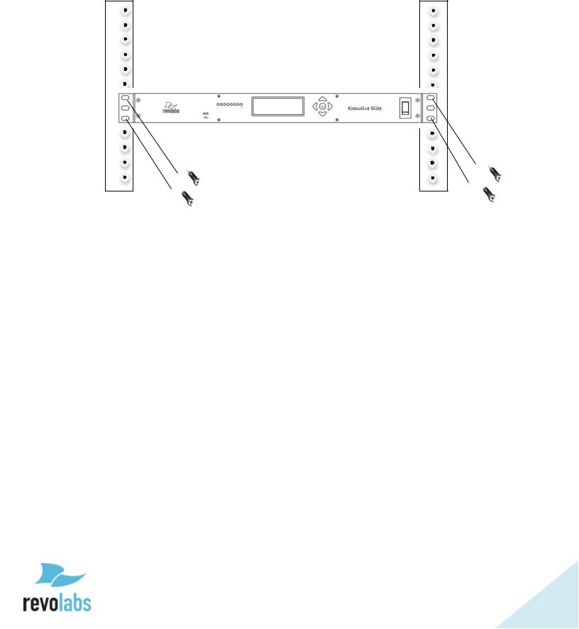
The Revolabs Executive Elite Base DSP Unit is designed to be installed into a standard 19” AV rack using the attached rack ears. Screws are not provided.
18
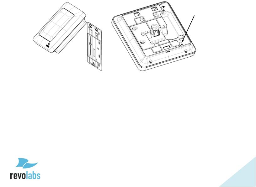
Remote Antenna Receiver
The Remote Antenna Receiver consists of two pieces – the mounting plate and the Antenna housing. The Remote Antenna Receiver is installed similar to a wireless access point. Best locations are high on the wall, facing into the room in which the microphones are located. Each Remote Antenna Receiver supports one Base DSP Unit. If more than one Base DSP Unit is installed for a room, e.g. more than eight microphones are required, several Remote Antenna Receivers will be installed in this room. It is best to install the receivers on the same wall facing into the room, spaced at least 12 inches (30 cm).
The Remote Antenna Receiver contains several antennas to provide the best transmission and reception of the radio signal to and from the microphones.
 Routing channels
19
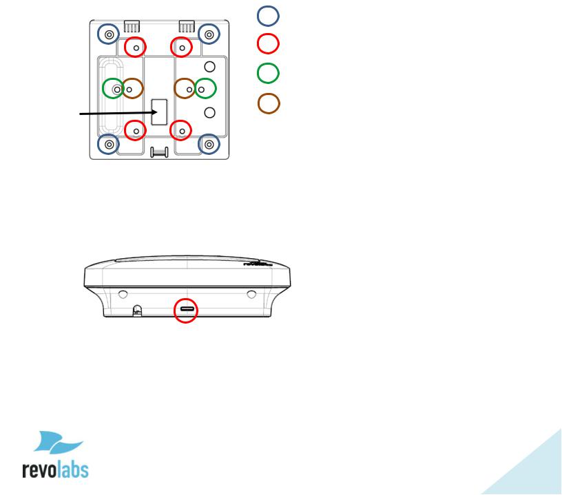
The back-plate of the Remote Antenna Receiver provides means to install the antenna in different environments. See the below diagram on how to install in the different environments.
Independent on which way the wall plate is attached, do not over-tight the screws.
When installed on the wall or on an electrical one gang or two gang box the network cable can be routed through the Network cable opening. Alternatively, the network cable can be routed to leave the Remote Antenna Receiver either on the top or the bottom, using the provided routing channels.
TOP
|
Four corner holes – wall installation |
|
Four central holes – US single gang |
|
or dual gang |
|
Two outside horizontal holes – |
|
European single gang |
Network |
Two inside horizontal holes – |
cable |
Under-ceiling installation |
opening |
|
Once the back plate is attached to the wall and the network wire is connected to the Remote Antenna Receiver and routed correctly, the Remote Antenna enclosure is attached to the back plate by slipping it from the top onto the two hooks, and then pressing the bottom back against the wall plate until the snap clicks in.
To separate the Remote Antenna Receiver housing from the wall plate insert a screwdriver from the bottom into the slit and press against the snap while carefully pulling the Antenna Receiver forward until the Antenna Receiver releases from the snap. The Remote Antenna Receiver housing can now be detached from the wall plate.
20
Connect Remote Antenna Receiver to Base DSP Unit
Connect the Remote Antenna Receiver with the Antenna output of the Base DSP Unit using a CAT 5e or Cat 6 cable.
NOTE: This needs to be a, point to point connection between the two units. This is a time crucial connection. Routing this connection through a switch will fail.
The Antenna output of the Base DSP unit provides Power over Ethernet which is required to power the Remote Antenna.
Before connecting the network cable, ferrite beads need to be installed on either end of the cable to minimize electro-magnetic interference. One ferrite bead should be attached ¼-⅜ of an inch (7 – 10 millimeters) from the end of the cable that will connect to the Base DSP unit. The second ferrite bead needs to be attached 5 inches (13 centimeters) from the end of the cable that will attach to the antenna.
NOTE: The Antenna Receiver provides room for the ferrite to be placed in the antenna casing, underneath the mount plate. If running the cable through the Network Cable Opening in the mount plate the ferrite must be installed after the cable has been pulled through. Otherwise it will not fit through the opening.
5 in |
1/4 – 3/8 in |
|
7 – 10 mm |
||
13 cm |
||
|
21

System set-up
Once the Remote Antenna Receiver has been connected to the Base DSP unit, connect that unit to the power mains and turn the switch on the front of the unit to “1” from “0”. The unit will now power up. You will see messages on the front screen providing information until the unit is operational. Once the Screen with the VU screen is shown, and the Antenna symbol is constant, the system is operational.
For additional system configuration instructions, see later sections describing the different user interfaces in this manual.
Revolabs Executive Elite Audio Connections
The Executive Elite Base DSP unit offers three different ways to deliver the audio from the microphones to post-processing equipment as well as to provide back channel audio to the microphones.
While all three audio output paths will be active at all times, only one of the back-channel audio paths can be active. The user interfaces allow selecting which path should deliver the audio back to the microphones.
Analog Audio
The back panel of the Executive Elite DSP eight channel base unit provides eight 3.5mm Euroblock inputs and eight 3.5mm Euroblock outputs (the four channel unit provides four input and four output connectors), providing access to each channel’s audio signal.
The Euroblock connectors included in the package are designed for easy wiring. The three terminals (from left to right) correspond to positive +, negative -, and shielded ground G.
To connect audio In/Out on the Base Station:
1.Use the screws on top of the connector to first open the terminals.
2.Insert an appropriate 3-conductor cable (2 conductors and shield) into the terminals.
3.Tighten the screw to secure the cable.
4.Push the connector onto the pins centered under the desired input or output port on the back of the Base DSP unit until firmly secured.
The microphone output connectors need to be attached to the line-level (0dBu) input connectors of the post-processing audio equipment (mixer, DSP).
If the analog audio in is used for the back-channel audio, the Base DSP Unit input connectors (also 0dBu) may then be attached to the output channels of the post-processing equipment.
22

AVB Audio
Beside the analog audio, Executive Elite also supports digital audio input and output. The AVB connection on the back of the Base DSP unit can be connected to an AVB enabled network and delivers streams of output audio data for each microphone, as well as can consume streams of input audio data for each microphone. For information on how to set up an AVB network and define AVB talkers and listeners see your AVB network management software.
Synchronizing Executive Elite units
If more than one Revolabs Executive Elite Base DSP unit is used in an area, the units should be synchronized to ensure best usage of the radio frequency space, and best system performance. The Executive Elite system provides three means to synchronize systems, the Sync Bus, the AVB network, and Over the Air synchronization.
Microphone Density and Radio Frequency Interference
Synchronizing Executive Elite systems is important to maximize the density of microphones that can be supported in one area. Non-synchronized systems in the same space block a higher number of radio frequency channels than the number of microphones they support, causing RF loss and audio drop-outs. It is therefore important to synchronize all Executive Elite systems that are in proximity with each other to limit the number of potential audio issues. There is no disadvantage in synchronizing systems that are not in close proximity. Synchronization only affects the internal clocks of systems, not the channel selection they make for their microphones. It is therefore better to error on the safe side and synchronize even systems not expected to be in direct proximity. Maximum Density of microphones in one area is affected by the selected audio quality and whether back-channel audio to the microphones is enabled or not. It is also dependent on other wireless radio frequency traffic in the vicinity, and whether that traffic is synchronized or not. Selecting the right RF power setting is important to limit the area in which RF traffic of a microphone and receiver is being seen to the coverage area, therefore reducing interference with adjacent areas. See later user interface sections for information on how to set these parameters.
Selecting Synchronization Method
Choosing a Synchronization method may be done through either the Web UI, or the Front Panel LCD.
From the Front Panel the synchronization mode may be selected from the System Clock submenu, under System Settings. Once the mode is selected, the interface will automatically prompt the user with a choice of Internal or External clock mode. Only one Internal can be set for any sync mode; this
23

device will be the clock source to all synchronized systems. All other devices need to be set as External, and use the clock signal of the Internal.
Through the Web UI, synchronization mode can be set on the System Configuration page. In the table on the bottom left of that page are two dropdown menus. The first is for the synchronization mode, and the second for setting the system as Internal (Primary on the Executive HD) or External (Secondary Mode on HD) clock mode.
Synchronization Bus
The synchronization bus allows connecting several Executive Elite Base DSP units together to manage the clock between the systems.
The Synchronization bus also allows synchronizing Executive Elite Base DSP units with Executive HD™ receivers in the same vicinity. While the synchronization bus in Executive HD installations also managed group mute control, this capability is handled differently in Executive Elite. When installed together with Executive HD systems the bus will therefore only provide synchronization data, not mute data between Executive Elite and Executive HD systems. However, mute groups managed between Executive HD systems can still be managed using the bus.
The synchronization bus cable is connected to the grey Euroblock BUS connector on the Executive Elite Base DSP unit using a standard 3.5mm Euroblock connector. The wire used should be 26AWG or better, shielded cable. The distance between the furthest External and the Internal must not exceed 300’ (90 meters).
The terminals of the BUS connector should be wired in parallel via either a daisy chain connection or terminal block split. The three contacts of the Euroblock connectors are as follows from left to right.
S.Sync
¯¯. Not used in Executive Elite (Master Mute in Executive HD)
G.Ground
If the synchronization bus is used to synchronize Executive Elite
systems with Executive HD systems, one of the Executive HD systems needs to be set as the Internal, making that system the clock master. All Executive Elite Base DSP units will have to be set to use the external clock.
AVB Synchronization
If all Executive Elite Base DSP units are connected to the same AVB network, the AVB network can be used to synchronize the systems with each other. This simplifies installation of Executive Elite systems as no additional
24

synchronization bus is required. However, it does not allow synchronization in a mixed environment with both Executive HD and Executive Elite systems as Executive HD Systems do not support AVB.
The Setup for ABV sync is through an AVB capable switch. Once the Executive Elite synchronization mode is set in the Web UI or Front Panel to AVB, select Auto as the Clock Mode. Through the AVB networking software set up a network of elite systems, where at least one system is a “Talker” and the other systems are “Listeners” to that system. The architecture also allows for communication chains, where one Elite is set up as a Listener to a system in the chain, and as Talker to systems further down in the chain.
OTA Synchronization1
Executive Elite systems have the ability to synchronize with other Executive Elite systems in radio frequency range using over the air (OTA) synchronization. This synchronization method does not require any wiring between Executive Elite Base DSP units. In OTA mode, systems exchange synchronization information using radio signals, therefore allowing systems in vicinity to auto synchronize. To enable OTA synchronization, select OTA as the Clock Source.
1 OTA Synchronization will be available starting with Executive Elite Software version 1.2
25

Front panel user interface
The Front panel user interface is one of four interfaces available to manage an Executive Elite system. The others are the local web UI, the Cloud Server Web UI, and the CLI (room control) interface and are described later in this document.
The front panel contains four areas:
1.On/off switch
2.4 / 8 LEDs (depending on the version of the Executive Elite base DSP unit)
3.Graphics LCD display
4.5 button navigation keypad.
The on / off switch powers the Executive Elite base and the connected remote antenna receiver on and off. During operation, this switch should be in the “1”, or ‘on’, position.
The LEDs on the front panel show the current microphone states. An LED that is off indicates that there is either no microphone paired to this channel, or the paired microphone is in the charger, out of reach, or switched off. A green blinking LED indicates an active microphone that is unmuted. A red blinking LED, showing a double blink, indicates an active microphone that is muted. A rapidly red blinking LED with a single blink indicates the microphone is upgrading. A constant red LED indicates a channel on which microphone pairing is taking place at the moment.
The LCD screen together with the navigation keypad allows easy monitoring of the Executive Elite system as well as managing some system settings without additional equipment. Its home screens provide information on audio levels, radio signal strength, and access to gain settings for the analog audio output. The menu structure displays system information, and allows changes to some system and audio settings. The front panel can also be used to pair and unpair microphones. It does not replace the local web UI interface or the cloud based management interface to manage all options and functionality of an Executive Elite system. The front panel interface will also not allow access to password protected areas of the interface unless the system has first been set up using the local web UI.
26

Home Screens
When starting an Executive Elite system, the first page that comes up on the Front Panel LCD is the Volume Unit (VU) screen. This screen is one of the 3 home screens on the Front Panel UI. Using the “up” and “down” keys to the right of the LCD while on the VU page will show the other two home screens.
The VU screen shows the audio volume for each unmuted, linked microphone, as well as battery charge information.
“Up” from the VU screen, the RF View home screen shows the radio signal strength as measured on the receiver for each microphone.
“Down” from the VU screen, the Gain control screen shows the VU meters as well as the input gain setting for each microphone channel, which the user can change from this screen. To adjust the gain, a user presses the “Enter” while on the gain screen, and a black highlighted selection will appear. The channel is selected using the “left” and “right” keys and once in the correct channel, the up and down keys change the gain in 1 dB steps. The gain setting for the highlighted channel is listed on the right-hand side of the LCD. The user cannot leave the gain control screen while in channel selection mode. To leave the screen, press “Enter” again to get into the normal mode. “Up” and “Down” will now switch between home screens again, and using the “Right” arrow key will enter the main menu.
27

When changing the gain or entering any menu in the front control panel that allows the user to changing values, a password prompt will appear before the user is allowed to proceed. To enter the password, use the right and left arrow keys to select a digit, and the up button to change the number of that digit (0- 9). Hitting Enter will submit the password, and down brings the cursor to the cancel button. On the front panel, the password will be valid for 20 minutes, unless the user explicitly logs out in the Admin Settings submenu as described further below. The factory preset password is 7386, and can be changed either through the Admin Settings menu on the front panel interface, or the System Configuration menu on the local Web UI.
28

All three home screens are split into 3 sections, and each section shows a different type of information. On the far right-hand side of the screen, the Home screen name is displayed at the top of the external systems information box. Underneath it there can be up to 4 icons, showing if certain external systems are connected.
 - Antenna. The only icon guaranteed to be in this box. If it is blinking, an antenna is not communicating with the Base DSP unit. If it is solid, communication is passing between the Antenna and Base.
 - Wired Sync. If a wired sync buss is being used to sync clocks between Executive systems, the synced Elites will show this icon. Remember that sync mode must be set before the base will look for an external clock.
 - USB. When the front panel USB is in use, this icon will show communication is being received through that port.
 - AVB. When AVB is plugged into the Base, the “AVB” icon will appear. Until the Base is set up as a “talker” or “listener”, the arrows above or below “AVB” will not appear. To check if the Base is set up for either, remember “T” is for talker and “L” is for listener.
Separated from the external systems box by a vertical line is the channel information section of the Front Panel UI. At the top, each channel is labeled, and two rows underneath provide different information depending on which home screen is currently selected.
On all screens, the top row will show microphone status beyond linked with the following icons:
 - Microphone Lost Link, or Unknown Status Microphone
 - Firmware Update in Process
  - Stand-by Mode
Microphone channels that have no microphone paired, a charging microphone, or when the microphone is switched off, will show no information.
29

Additional information from this row can be found in the following forms:
- Mute Symbol. Will show on the VU screen for a linked, muted microphone.
 - VU or Gain Meters. VU screen shows a VU meter for a linked, unmuted microphone, while the Gain screen meters look the same, but do not change unless set, and appear for all linked microphones.
 - RF Meters. The RF screen will display the strength of the transmission from any linked microphone as it is received by the base. Microphones experiencing interference or far away will have a lower RF.
The second row displays battery information when seen on the VU and RF screens, using the following icons:
 - For a linked microphone, the battery level icon will show the charge level by the amount of black in the battery.
 - While in the charger, the battery symbol also shows a charging symbol overlaid over the battery-charge icon2.
 - A microphone using a permanent cross-over adapter will be shown with a power connector battery symbol. A permanent cross-over adapter is one where the microphone does not use batteries.
 - A battery symbol with a +/- indicates a non-rechargeable battery or wrong battery type. Such a battery will not charge when placed in the charger tray.
 - The type of a battery is only determined when the microphone is placed in a charger after inserting a new battery. Up until this time the battery symbol will show a battery with a question mark in it, indicating that the battery type is unknown.
 - Low battery, under 10% remaining.
 - Very low battery, under 5% remaining.
On the gain screen, this row will not show battery information, instead having a row of digital gain “knobs” that will match the gain shown in the meters above them.
 - Gain knob
2 It might take a few minutes for the charge symbol to appear after a microphone was placed in the charger.
30
Loading...