

Revolabs 01-8FUSIONEU-62, 05-TBLMICEU-OM-BLK-11, 01-4FUSIONEU-31, 03-EXEMICEU-BLK-11, 03-EXECHGEU-STD-11 Installation And User Manual
...Page 1

Microphones must be fully charged and paired to the
Charger Base prior to first use.
Rev 1.1
Revolabs Fusion™ Wireless
Microphone System
Installation and User’s Guide
Page 2
Page 2
Table of Contents
8-Microphone System
01-8FUSION-NM or 01-8FUSIONEU-NM (No microphones)
01-8FUSION-62 or 01-8FUSIONEU-62 (6 omni tabletops/2 wearable)
4- Microphone System
01-4FUSION-NM or 01-4FUSIONEU-NM (No microphones)
01-4FUSION-31 or 01-4FUSIONEU-31 (3 omni tabletops/1 wearable)
Part Numbers Covered in This Document
Page 37
EUROPEAN COMPLIANCE
This equipment has been approved in accordance with Council Directive
1999/5/EC “Radio Equipment and telecommunications Equipment.
Conformity of the Equipment with the guidelines below is attested by the CE
mark.
Model Numbers:
01-8FUSIONEU-NM Revolabs Fusion Base Station, European
01-4FUSIONEU-NM Revolabs Fusion Base Station, European
01-8FUSIONEU-62 Revolabs Fusion System with 6 tabletop
omni’s & 2 wearable mics, European
01-4FUSIONEU-31 Revolabs Fusion Base System with 3
tabletop omni’s & 1 wearable mics,
European
03-EXEMICEU-BLK-11 Revolabs Solo™ Executive Microphone
03-EXECHGEU-STD-11 Revolabs Solo™ Executive Charger
05-TBLMICEU-OM-BLK-11 Revolabs Solo™ Executive Table
Microphone Omni
05-TBLMICEU-DR-BLK-11 Revolabs Solo™ Executive Table
Microphone Cardioid
06-XLRMICEU-OM-BLK-11 Revolabs Solo™ Executive XLR
Microphone Adapter
STANDARDS TO WHICH CONFORMITY IS DECLARED:
RF ETSI EN 301 406 V 1.4.1 03/2001
EMC ETSI EN 301 489-6 v1.2.1 (2002-04)
WEEE NOTIFICATION:
The Waste Electrical and Electronic Equipment (WEEE) directive (2002/96/EC)
is intended to promote recycling of electrical and electronic equipment and their
components at end of life.
2003/11/EC & 2002/95/EC “ROHS COMPLIANCE DIRECTIVE”:
The products referenced herein are in compliance with the EU directive
2003/11/EC and EU directive 2002/95/EC.
SAFETY COMPLIANCE
TUV SUD AMERICA
Revolabs Fusion™
Page 3

INDUSTRY CANADA NOTICE TO USERS
Operation is subject to the following two conditions:
(1) This device may not cause interference and
(2) This device must accept any interference, including interference that may
cause undesired operation of the device.
IC: 6455A-01FUSION Revolabs Fusion™ Base Station 8 microphones
IC; 6455A-01FUSION4 Revolabs Fusion™ Base Station 4 microphones
IC: 6455A-01EXEMIC Revolabs Solo™ Executive Microphone
RESTRICTED USE WITH CERTAIN MEDICAL DEVICES
Hearing Aids
Some devices may interfere with some hearing aids. In the event of such
interference, you may want to consult with your hearing aid manufacturer to
discuss alternatives.
Other Medical Devices
If you use any other personal medical device, consult the manufacturer of your
device to determine if it is adequately shielded from RF energy. Your physician
may be able to assist you in obtaining this information.
EXPORT LAW ASSURANCES
This product is controlled under the export regulations of the United States of
America and Canada. The Governments of the United States of America and
Canada may restrict the exportation or re-exportation of this product to
certain destinations. For further information contact the U.S. Department of
Commerce or the Canadian Department of Foreign Affairs and International
Trade. The use of wireless devices and their accessories may be prohibited or
restricted in certain areas. Always obey the laws and regulations on the use of
these products.
01-FUSION-8CH-NA & 01-FUSION-4CH-NA North America UPCS
Usage Restriction
Due to the UPCS frequencies used, this product is licensed for operation only in
the United States of America and Canada.
01-FUSION-8CH-EU & 01-FUSION-4CH-EU European Union Usage
Restriction
Due to the DECT frequencies used, this product is licensed for operation only
in the European Union countries.
Page 36
Installation Guide
Revolabs Fusion™
Page 3
Great audio, wireless mobility, and simple to install!
Simply plug the cable into the AV system or phone system and it
works. No software configuration is necessary. Even the Fusion
box is designed to be easy to use– vertically or horizontally. No
equipment rack needed! Just set the Fusion system on the
credenza!
Video Conferencing
Revolabs Fusion Wireless Microphone Solution includes all of the
necessary cables to plug into any of the major video-conferencing
solutions, including Lifesize, Polycom, Sony and Tandberg. It
includes a remote control to control the sound volume in your
conference room or in the conference room at the far end. Decide
on where you want to put the Fusion system, whether you want to
place it vertically or horizontally, plug in the cables and you are
ready to have great wireless audio in any conference room!
Audio Conferencing
Plug the Fusion Wireless Microphone Solution into a telephone
system and you are on your way to great wireless audio. There is a
remote control dialer to dial the conference phone number and you
may purchase new powered speakers or use existing powered
speakers to hear the call. Decide on where you want to put the
Fusion system, whether you want it vertical or horizontal, plug in
the cables and you are ready to have great wireless audio in any
conference room!
Rechargeable
These Wireless Microphone Systems have a rechargeable battery
that provides eight hours of talk time after each full charge.
Revolabs Wireless Microphones recharge to 85% capacity in
approximately 45 minutes.
Secure
All of Revolabs Wireless Microphones use 128-bit encryption, so
that no one can listen in.
Page 4
Installation Guide
Page 4
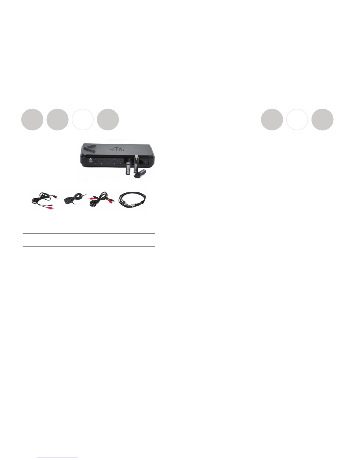
Contents of box:
Fusion Base Station, Fusion Base
Station vertical stand, AC power
adapter for Base Station, four
cables shown below, remote
control, Charger Base, AC wall
adapter for Charger Base, four
or eight wireless microphones
(optional). Optional boxes:
Four or eight wireless microphones, Remote IR Sensor, speakers.
Fusion Set-up
Decide if want to place Fusion Base Station horizontally or vertically on a flat
surface. To set-up vertically, place the Fusion Base Station vertical stand on the
bottom of the Fusion unit. Tighten bolt into Fusion Base Station.
Fusion Base Station Placement
WARNING: Do not put Fusion Base Station behind metal doors.
If you are putting Fusion into a cabinet with non-metal doors, you need to use
the Remote IR Sensor (part number 07-IRREMO-01) for remote to work. Plug
the serial port end into the IR Remote port on the back Fusion panel, bring IR
Sensor out of cabinet, and secure with Velcro.
Power
Plug power cord into the back of the Fusion Base Station and into wall outlet.
Plug AC Adapter into the power outlet and the other end into the microphone
Charger Base.
Place wireless microphones in the Charger Base, let charge overnight or at least
eight hours.
CABLE A
Speakers
CABLE B
Phone Cable
CABLE C
RCA
CABLE D
XLR
Page 35
NOTE: This equipment has been tested and found to comply with the limits
for a Class B digital device, pursuant to part 15 of the FCC Rules. These limits
are designed to provide reasonable protection against harmful interference in a
residential installation. This equipment generates, uses, and can radiate radio
frequency energy and, it not installed and used in accordance with the instructions, may cause harmful interference to radio communications. However, there
is no guarantee that interference will not occur in a particular installation. If this
equipment does cause harmful interference to radio or television reception,
which can be determined by turning the equipment off and on, the user is encouraged to try to correct the interference by one or more of the following
measures:
• Reorient or relocate the receiving antenna.
• Increase the separation between the equipment and receiver.
• Connect the equipment into an outlet on a circuit different from that to
which the receiver is connected.
• Consult the dealer or an experienced radio/TV technician for help.
Revolabs Fusion™
Page 5

Safety and General Information
Please read the following information to ensure safe use of your Revolabs
system.
FCC User Information
FCC Registration Number: 0014898290
FCC ID: T5V-01-FUSION Revolabs Fusion™ Base Station 8 microphones
FCC ID: T5V-01-FUSION4 Revolabs Fusion™ Base Station 4 microphones
FCC ID: T5V-01-EXEMIC Revolabs Solo™ Executive Microphone
FCC NOTICE TO USERS
Users are not permitted to make changes or modify the equipment in any way.
Changes or modifications not expressly approved by Revolabs, Inc. could void
the user’s authority to operate the equipment. To meet FCC and Industry
Canada RF radiation exposure limits for general population (uncontrolled
exposure), a minimum of 7.9 inches (20 cm) separation distance must be
maintained between the Fusion Base Station and users' and/or nearby persons'
bodies at all times. Additionally, the Fusion Base Station must not be co-located
with any other antenna or transmitter.
This device complies with Part 15 of the FCC Rules. Operation is subject to the
following two conditions: (1) this device may not cause harmful interference,
and (2) this device must accept any interference received, including interference
that may cause undesired operation.
This product has been found to comply with the Rules of 47 CFR Part 68 of the
Federal Communications Commission and Technical Requirements For
Connection of Terminal Equipment to the Telephone Network TIA-968-A-1, A2 and A-3.
Certificate Number: US:6RMBR00BNEXIATC Date: April 14, 2006
IMPORTANT NOTE: FEDERAL COMMUNICATIONS COMMISSION
(FCC) RADIATION EXPOSURE STATEMENT
This equipment complies with FCC radiation exposure limits for an
uncontrolled environment.
Page 34
Installation Guide
Revolabs Fusion™
Audio Conferencing
Plug Cable A (single RCA to double RCA) single RCA connector into Fusion
Base Station <Room Out> RCA port, and then plug the double RCA connectors
into the speakers. Plug speakers into wall outlet. Must be powered speakers or
a powered amplifier.
Plug one end of Cable B, the phone line cable, into the Fusion Base Station
<Line In>, plug other end into phone jack. Dial with the remote.
If you ordered 01-8FUSION-62 6 omni tabletops/2 wearable microphones or
01-4FUSION-31 3 omni tabletops/1 wearable microphone. You are all set to
go! Take out the Wireless Microphones, unmute them by pressing the mute
button on the microphone and the system is ready for a conference!
If you selected your microphones separately with the 01-8FUSION-NM or
01-4FUSION-NM Fusion part numbers, you must first establish a connection
between your microphones to the Fusion Base Station. This is called “pairing”.
Refer to page x.
Video Conferencing
You must have the audio output going to a display with speakers
coming from the Fusion Base Station, not the Video-conferencing
Station. Plug Cable A (single RCA to double RCA) single RCA connector
into Fusion Base Station <Room Out> RCA port and then plug the double RCA
connectors into the speakers or display with speakers.
Once you have configured your video-conferencing station as follows, then:
If you ordered 01-8FUSION-62 6 omni tabletops/2 wearable microphones or
01-4FUSION-31 3 omni tabletops/1 wearable microphone. You are all set to
go! Take out the Wireless Microphones, unmute them by pressing the mute
button on the microphone and the system is ready for a conference!
If you selected your microphones separately with the 01-8FUSION-NM or
01-4FUSION-NM Fusion part numbers, you must first establish a connection
between your microphones to the Fusion Base Station. This is called “pairing”.
Refer to page x.
Page 5
Page 6

Installation Guide
Lifesize Installation
Plug red RCA connector of Cable C, the double RCA to double RCA cable,
into the Fusion Base Station <Conf Out>, then plug the other end red RCA
connector into the Lifesize video-station <Conf In>. Plug black RCA connector
of Cable C, into the Fusion Base Station <Conf In>, and the other black RCA
connector into the Lifesize video-station <Conf Out>.
Specifications
Dimensions, (L, W, H) and Weight:
Fusion Base Station 16.45” (41.8 cm) x 8.46” (21.5 cm) x 1.7” (8.7 cm), 8.7 lbs (3.95 kg)
Charger Base 8.3” (21.1 cm) x 4.3” (10.9 cm) x 1.0” (2.56 cm), 1.0 lb (0.45 kg)
Wireless Microphones Wearable: 0.9” (2.3 cm) x 0.8” (2.0 cm) x 2.6” (6.6 cm), 0.05 lb (0.02 kg)
TableTop: 1.5” (3.8 cm) x 0.8” (2.0 cm) x 3.3” (8.4 cm), 0.05 lb (0.02 kg)
XLR Adapter: 0.9” (2.3 cm) x 0.8” (2.0 cm) x 4.0” (10.2 cm), 0.05 lb (0.02 kg)
Radio Frequency:
01-8FUSION-XX 1.92 to 1.93 GHz (UPCS North America)
01-4FUSION-XX 1.92 to 1.93 GHz (UPCS North America)
01-8FUSIONEU-XX 1.88 to 1.90 GHz (DECT EU)
01-4FUSIONEU-XX 1.88 to 1.90 GHz (DECT EU)
Connectors:
Fusion Base Station
IR Remote Serial DB9
CD Programming Serial DB9 - for Revolabs use only
Audio Control RJ45 – for Revolabs use only
Telephone Line-In RJ11
Telephone Set-In RJ11
Network RJ45 – for Revolabs use only
XLR male
Aux In RCA Plug
Aux Out RCA Plug
Record Out RCA Plug
Room Out RCA Plug
Conference In RCA Plug
Conference Out RCA Plug
Charger Base DC power input port, Proprietary 4 pin microphone charge jacks
Microphone Proprietary 4 pin charge plugs, 2.5mm mono earplug port
Power Requirements:
Fusion Base Station 100-240V AC, 50-60 Hz, 10W (power cable varies by country)
Charger Base 5V DC, 2 Amps (switching power supply varies by country)
Range: 100’ (30 meters) approx. (no obstructions)
Maximum Microphones:
01-8FUSION-XX, 01-8FUSIONEU-XX 8 channels maximum
01-4FUSION-XX, 01-4FUSIONEU-XX 4 channels maximum
Battery: Lithium Polymer, 8 hours approx. talk time
Charge Time: 2 hours approx.
Audio Bandwidth 100-7000 Hz
Security: 128-bit DSAA (DECT Standard Authentication Algorithm) authentication,
64 bit DECT Standard Cipher
Page 33
Revolabs Fusion™
Page 7

Warranty
Revolabs, Inc. warrants this product to be free of manufacturing defects.
Repair or replacement of any defective part or unit (at the discretion of the
Seller) will be free of charge for the period of one year.
Any attempt by the user to alter the equipment, or equipment damaged by
negligence, accident, or Acts of God voids this warranty.
The Seller shall not be liable for any consequential damage resulting from
the malfunction of this product. Should the user experience unsatisfactory
performance from this equipment, contact the Seller to obtain instructions for
return, or replacement, as deemed necessary.
This warranty is not transferable by the original end user.
Revolabs, Inc.
63 Great Road
Maynard, MA 01754
www.revolabs.com
800.326.1200
Page 32
Installation Guide
Revolabs Fusion™
Page 7
Page 8

Polycom Installation
Plug red RCA connector of Cable C, the double RCA to double RCA cable,
into the Fusion Base Station <Conf Out>, then plug the other end red RCA
connector into the Polycom video-station <Conf In>. Plug black RCA connector
of Cable C, into the Fusion Base Station <Conf In>, and the other black RCA
connector into the Polycom video-station <Conf Out>.
Page 8
Installation Guide
tation
el LEDs
Meaning
Charging in Progress
Charging Complete
Microphone powered OFF or battery discharged
lashing Microphone paired and muted
N Flashing Microphone paired and “live”
ED Pairing mode or confirmation of
powering-down.
rnating slow
N and RED
Microphone or channel not
paired
N Flashing Microphone low battery
(mic live)
lashing Microphone low battery
(mic muted)
Searching for a connection, or
out of radio range. The Microphone will try to re-establish the
link for about 15 minutes, and
then turn off automatically.
Radio congestion – it is not possible to make a radio connection
because there are already too
many nearby users, or there is
heavy radio interference. Possibilities include some types of
digital cordless phones, and
other Solo installations.
Unit is faulty. Contact your AV
service provider for advice.
Page 31
Revolabs Fusion™
Page 9

Revolabs Solo™ Indicator LED
Equipment Use Microphone LED Base
S
Chan
n
Microphone in Charger
Base
Solid RED OFF
Solid GREEN* OFF
Microphone not in
Charger Base
OFF OFF
Two RED flashes every
1.5 seconds
RED
F
GREEN flash every 1.5
seconds
GREE
Solid RED Solid
R
Alternating slow
GREEN and RED
OFF
or Alt
e
GREE
YELLOW flash alternat-
ing with GREEN
GREE
YELLOW flash alternat-
ing with two RED
flashes
RED
F
Alternating RED, YEL-
LOW, GREEN, YELLOW
OFF
Rapid RED flashes con-
tinuing for more than a
few seconds
OFF
Groups of five rapid
RED flashes
OFF
Page 30
Installation Guide
Page 9
Revolabs Fusion™
Page 10

SONY INSTALLATION
Requires special cable of XLR connector to 3.5 mm phono connector.
Page 10
Installation Guide
The Adapter does not provide phantom power or bias current so it cannot be
used with condenser or electret microphones.
With the microphone attached, un-mute the Adapter by pressing and releasing
the Mute button (confirm by viewing flashing GREEN LED).
If the microphone has an on-board mute switch, this switch must also be un-muted
prior to use.
To turn the Adapter off, return the microphone unit to the Charger Base or
press and hold the Mute button for ~10 seconds until the LED turns solid RED
and release button.
Important: Always remove the microphone from the Adapter by pressing the
latch switch and separating the parts before returning the Adapter to the
Charger Base.
If the Adapter is moved too far from the Base Station (~100 feet or 30 meters)
the connection will be dropped (LED flashes all colors) and the audio will mute.
After 15 seconds the microphone will beep 5 times, and will continue beeping
every 30 seconds to indicate that it is out of range.
Move the XLR Adapter closer to the Base Station and the connection will
automatically be re-established to its original state, and the beeping will cease. If
not, the XLR Adapter will continue beeping until it
turns off in about 15 minutes.
Page 29
Revolabs Fusion™
Page 11

Using the Solo XLR Microphone Wireless Adapter
The Revolabs Solo™ Universal Wireless Adapter for Handheld Microphones,
shown in the following figure, is connected to your existing handheld dynamic
microphones for wireless freedom during open microphone meetings, Q&A
sessions, classrooms, etc.
1. Mute button — press to mute, un-mute and pair microphone.
2. Rubber collar — durable and impact/strain protection.
3. XLR Female connector — balanced audio for dynamic microphones.
4. LED display — visual status for mute, un-mute, and pairing.
5. Audio Out port — accepts the 2.5mm plug for the earpiece
6. Power/Charging Port — docks to Charger Base
To use the Revolabs Solo™ Universal Wireless Adapter:
Remove the Microphone Adapter from the Charger Base.
The adapter turns on and mutes automatically when removed from Charger
Base (flashing RED LED). The XLR Microphone Adapter is attached to a
standard dynamic microphone to convert it from a wired microphone to a
wireless microphone (see following figure).
Page 28
Installation Guide
Page 11
Revolabs Fusion™
Page 12

Tandberg Installation
Step 1 Step 2
Plug both RCA connectors on one end of Cable C into Tandberg video-
station <Audio Out>, then plug one RCA connector on the other end,
(red or black) into the Fusion Base Station <Conf In>. The other
RCA connector is not used.
Plug one XLR connector of Cable D, XLR to XLR, into Tandberg video-
station <Mic 1 Input> and the other RCA connector into the Fusion
Base Station <Conf Out>.
Page 12
Installation Guide
Page 27
• TableTop microphones should be centered on the table with the integral
grill pointed toward the users (uni-directional), or centrally located
between users (omni-directional), from 2 to 5 feet (.75 to 1.75m) away. It
is always better to be as close to the person speaking as possible, but avoid
placing the microphone where it might be blocked by equipment or
meeting paperwork. Also do not place microphones too close to an audio
or video conference speaker to avoid echoes.
• With the microphone in position, un-mute the microphone by pressing and
releasing the Mute button (confirm by viewing flashing GREEN LED).
• To turn microphone off, return the microphone unit to the Charger Base
or press and hold the Mute button for ~10 seconds until the LED turns
solid RED and release button.
• If the microphones are placed too far from the Base Station (~100 feet or
30 meters) the connection will be dropped (LED flashes all colors) and the
microphone will mute. After 15 seconds the microphone will beep 5 times,
and will continue beeping every 30 seconds to indicating it’s out of range.
• Move the microphone closer to the Base Station and the connection will
automatically be re-established to its original state, and the beeping will
cease. If not, the microphone will continue beeping until it turns off in
about 15 minutes.
Revolabs Fusion™
Page 13

Using Solo Tabletop Wireless Boundary Microphones
The Solo TableTop Wireless Boundary Microphones enable multiple conference
attendees to use a single microphone.
The TableTop Wireless Microphone, shown on the following page, is designed
to provide optimum coverage when placed on a conference room table.
1. Mute button — press to mute, un-mute and pair microphone.
2. LED display — visual status for mute, un-mute, and pairing.
3. Integral grille — protects internal parts (non-removable).
4. Audio jack — accepts a 2.5mm plug
5. Charging port — docks to all Solo Charger Base
6. Rubber feet — non-slip, vibration absorbing pads.
To use the Revolabs Solo™ TableTop Microphone:
Remove the microphone from the Charger Base to turn on and automatically
mute the mic (indicated by a flashing RED LED) during placement on the
conference table.
Page 26
Installation Guide
Page 13
To
configure the Tandberg system:
Go to Audio Settings.
Set Input 1 to MIC.
Confirm that Output 1 is ON.
Disable Echo Canceller (OFF).
Turn Audio Leveling (AGC) OFF.
Adjust the audio Input Type Level if necessary.
Speak into the Revolabs microphones that are connected to the audio line
inputs.
The audio meter should peak at about 5 d
Revolabs Fusion™
Page 14

Pairing Wireless Microphones to Fusion
Base Station
If you selected your microphones separately with the 01-8FUSION-NM or 014FUSION-NM Fusion part numbers, you must first establish a connection
between your microphones to the Fusion Base Station. This is called “pairing”.
Pairing creates a link with a unique electronic serial number between the Solo
wireless microphone and the Fusion Base Station. When the microphone and
Base Station have been previously paired, the microphone will automatically try
to connect to the Base Station whenever it is lifted from the Charger Base.
Note: Microphones in new systems must be paired to the Base Station
with each microphone assigned to a unique channel on the base unit.
Remember, microphones are always muted (flashing RED LED) when they are
removed from the Charger Base and the Mute button needs to be pressed to
make it “live” (flashing GREEN LED).
A microphone that is not paired will be indicated by either cycling RED-GREEN,
or RED-YELLOW-GREEN LED patterns. A Base Station LED that is not paired
to a microphone will not show any activity on the LED (make sure unit is first
powered on by observing GREEN power LED on the front panel).
When the microphone and Fusion Base Station are paired, both microphone
and channel LEDs will flash RED as microphones are removed from the Charger
Base and flash GREEN when un-muted.
To pair the microphone to the Fusion Base Station:
Turn the microphone OFF (no LED activity). If the microphone is ON, press
and hold the Mute button for 10 seconds until the LED turns solid RED (do not
release when you hear two beeps). Release the button to turn the unit off.
Page 14
Installation Guide
Page 25
Revolabs Solo™ Wearable Microphones turn on and mute automatically when
removed from Charger Base, to reduce noise while being attached. The
microphone has a clip on the back which allows the microphone to be easily
attached onto a shirt pocket, blouse, lapel or lanyard.
To use the Wearable Microphone:
• Remove the microphone from the Charger Base.
• Attach the microphone to clothing or to a lanyard close to the mouth,
within 6 - 12 inches (15 – 30cm) is recommended. Make sure microphone
is attached securely with the microphone port pointed up toward mouth.
• With the microphone in the wearing position, un-mute the microphone by
pressing and releasing the Mute button (confirm by viewing flashing GREEN
LED). If the volume is too low, move the microphone closer to the mouth.
• To turn microphones off, return the microphone unit to the Charger Base
or press and hold the Mute button for ~10 seconds until the LED turns
solid RED and release button.
• If the microphones are moved out of range of the Base Station (~100 feet
or 30 meters) the connection will be dropped (LED flashes all colors) and
the microphone will mute.
• After 15 seconds the microphone will beep 5 times, and will continue
beeping every 30 seconds to remind the user to return the microphone to
the conference room. If the microphone is moved back into range within
15 minutes the connection will automatically be re-established to its
original state, and the beeping will cease. If not, the microphone will turn
off.
Revolabs Fusion™
Page 15

Using Revolabs Microphones and
Microphone Adapters
Use any Solo Microphone microphones with your Revolabs Solo™ Executive
system:
• Revolabs Solo™ Wearable Wireless Microphone
• Solo Tabletop Wireless Boundary Microphone
• Solo Universal Wireless Adapter for Handheld Microphone
Using Revolabs Solo™ Wearable Wireless Microphone
The Revolabs Solo™ Wearable Microphones, shown in the following figure, are
paired to the Base Station and can be worn on the user’s shirt pocket, lapel or
on a lanyard.
1. Microphone port — direct port toward mouth for best audio pickup.
2. Noise cancelling port — do not block opening.
3. Mute Button — press to mute, un-mute and pair microphone.
4. Pocket clip — also used to attach microphone to lanyard.
5. LED display — visual status for mute, un-mute, and pairing.
6. Earpiece jack — accepts the 2.5mm plug for the earpiece
7. Charging port — charges in Charger Base.
Page 24
Installation Guide
Page 15
Place the microphone unit into pairing mode by holding the Mute button down
for seven seconds. The LED will turn solid RED. Release the Mute button. The
microphone is now in pairing mode.
Within one minute, push and hold the button for the desired channel on the
Base Station for seven seconds to enter into pairing mode then release. The
LED for that channel will be solid red until pairing starts, as indicated by a quick
GREEN flash, then switching to flashing RED on both the microphone and the
Base Station (muted audio). Pairing is now complete.
The Fusion Base Station has four or eight indicator LEDs (one for each
microphone) and pairing push buttons on the front panel. When the LED is
flashing GREEN or RED, that channel is active and connected to a wireless
microphone (GREEN is for live audio, RED is for muted). When the LED is OFF,
the channel is inactive (the microphone is out of range or turned off).
Revolabs Fusion™
Page 16

Details about the Revolabs Fusion
Fusion Front Panel
The Revolabs Fusion Base Station, shown below in front and rear panel
views, manages wireless audio signal processing, and pairing between the
Revolabs microphones and the Fusion Base Station.
1. IR Remote receiver (if not in sight range of remote, page x)
2. LED indicators: Displays microphone mute and pairing states
3. Pairing Push Buttons: For pairing microphones to Base
Station (page x)
4. Power On LED/Volume indicator
Page 16
Installation Guide
Page 23
Using the Revolabs Fusion™ Charger Base
When Microphones are not in use, they should be properly inserted into
the Charger Base. It is important to ensure that the system microphones are
inserted fully in the base so that charging will occur. Features of the base are
shown in the following figure.
LED indicator — power / mute status indicator.
Charger Bay — charges up to 8 Microphones.
Power Cord Receptacle— power supply input (on rear).
The Charger Base requires 5VDC power, provided by the AC Adapter.
Plug the supplied AC adapter into an appropriate power outlet 110-240 AC, 5060Hz. The power LED on the Charger Base will illuminate.
Charging the Microphone Batteries
First-time use — before using the wireless microphone the first time,
charge the batteries in the microphones for eight hours (or
overnight) in the
Charger Base.
2
1
3
Revolabs Fusion™
Page 17

Using the Revolabs Fusion™ IR Remote
Control
NOTE: A fully charged battery provides
approximately 8 hours of talk time
Page 22
Flash – phone function
Vol + : increases far-end volume
Call: phone off-hook (dial-tone)
End: phone on-hook (hangup)
Vol -: decreases far-end volume
Phone Dial Pad
Installation Guide
Page 17
Fusion Back Panel
1. Power
2. 6 RCA Plugs
• AUX IN
• AUX OUT
• RECORD OUT
• ROOM OUT
• CONFERENCE IN
• CONFERENCE OUT
3. XLR
4. Network RJ 45 (Revolabs use only)
5. Telephone Line-in RJ11
6. Telephone Set-in RJ11
7. Audio Control RJ45 (Revolabs use only)
8. Programming Port: LEFT DIP Switches 1-8 (refer to page x)
9. Programming Port: RIGHT DIP Switches 1-8 (Revolabs Use
Only)
10. IR Remote
11. DB9 (Revolabs use only)
Revolabs Fusion™
Page 18

Programming Port: DIP Switches
The Fusion Base Station factory default settings are all OFF. The left
Programming Port (#8, page 17) is end-user configurable: Switches 1 and 2 are
used for transmit power settings (default high power), 3 and 4 for frequency
mode settings (default unrestricted mode), 5 for tabletop mute behavior setting
(default no tabletop master mute) and switch 6 for Auto Answer (default off).
Programming Port (#9, page 17) on the right is reserved for Revolabs Use Only.
OFF
ON
Transmit Power Medium
Frequency A Mode
Tabletop Master Mute
Frequency B Mode
Auto Answer
Transmit Power Low
1 2 3 4 5 6 7 8
Page 18
Installation Guide
Programming Ports DIP Switches Used for
Phone Answering
Setting Phone Answering Mode
Answer with Remote Control (default)
To answer a phone call and begin a teleconference, the user must use the
Remote Control and press the “answer” key. DIP switch #6 is OFF.
Auto Answer
The Fusion Base Station will answer all calls. DIP switch #6 is ON.
Page 21
Revolabs Fusion™
Page 19

Programming Ports DIP Switch Used for
Muting Option
Setting the Mute Option
Individual Muting (default)
Each Solo microphone will mute only itself when its mute button on the
microphone is pressed. If the mute button on the remote control is pressed, all
microphones are muted (all mics will flash red LEDs). In this master muted
state, the individual mute buttons on the microphones themselves will be
ignored, to prevent accidental un-muting. To disengage master mute, the mute
button on the remote control should be pressed again. All microphones will
return to their prior state. DIP switch #5 is OFF.
Tabletop Microphone Master Mute
Solo wearable and XLR type microphones will mute only themselves only when
the mute button on the microphone is pressed. Pressing the mute button on
any Solo Tabletop microphone, will mute all active tabletop microphones;
wearable and XLR type microphones will remain unaffected by the tabletop
mute. Pressing any tabletop microphone mute button will disengage the
tabletop mute. If the mute button on the remote control is pressed, all
microphones are muted (all mics will flash red LEDs). In this master muted
state, the individual mute buttons on the microphones themselves will be
ignored to prevent accidental un-muting. To disengage master mute, the mute
button on the remote control should be pressed again. All microphones will
return to their prior state. DIP switch #5 is ON.
Page 20
Installation Guide
Programming Port Settings for Multiple
Fusion Systems
There are two settings that must be adjusted when more than one Fusion
system is used within a 100’ (30.5 m) foot range: frequency and transmit power
level. These settings will enable several Fusion systems to be used near each
other, but not interfere with each other. Interference between systems can
cause occasional audio noise and signal dropouts on affected systems. Building
conditions may influence this distance.
NOTE: Even using the settings below, the 8- Microphone Fusion System
requires 40 feet (12.2 m) between systems.
Setting the Transmit Power Level for Multiple Fusion Systems
In confined settings where multiple Fusion systems are used, or where audio
interference is likely, it may be necessary to reduce the transmit power levels.
The transmit power level between the Microphone and Charger Base can be set
to the following three levels:
• Highest power level (default) – 100 feet (30.5 m) maximum operating
distance between Microphone and Charger Base DIP Switches #1 and #2
are OFF.
• Medium power level – 30 feet (9 m) maximum operating distance between
Microphone and Charger Base. DIP Switch #1 is ON and DIP Switch #2 is
OFF.
• Lowest power level – 8 feet (2.4 m) maximum operating distance between
Microphone and Charger Base. DIP Switch #2 is ON and DIP Switch #1 is
OFF.
Frequency Settings
Frequency should be alternated to different frequency ranges, A and B. So an
example of five conference rooms in a row would be configured:
To configure the Fusion to frequency mode A, Dip Switch #3 is ON and DIP
Switch #4 is OFF. Frequency mode B - Dip Switch #4 is ON and DIP Switch #3
is OFF.
Conference
Room
1 2 3 4 5
Frequency A B A B A
Conference
Room
1 2 3 4 5
Frequency A B A B A
Page 19
Revolabs Fusion™
 Loading...