

Page 1
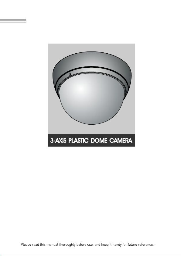
Super High Resolution
Color Camera
540TV Lines
INSTRUCTION MANUAL
Page 2

LIMITATIO N OF LIABILITY
TH E I NFO RMAT ION IN TH IS PU BLI CATI ON IS BE LIE VE D TO BE ACC UR ATE IN
AL L RES PEC TS, HOWE VER , WE CAN NOT ASS UME R ESP ONS IB ILI TY FOR A NY
CON SE QUE NCES RES ULTI NG FROM THE US E T HEREO F. THE I NFO RMAT ION
CON TAI N ED HE REI N IS SUB JEC T T O CHANGE WI THO UT NOTI CE . REVI SIO NS
OR NE W E DI TIO NS TO THI S P UB LIC ATIO N MAY BE IS SUED TO INCORP ORAT E
SU C H CHA NGE S.
ii
Page 3
WARNINGS AND CAUTIONS:
CAUTION:
CAUTIONCAUTION
CAUTION: TO REDUCE THE RISK OF ELECTRIC SHOCK,
DO NOT REMOVE COVER(OR BACK).
NO USER-SERVICEABLE PARTS INSIDE.
REFER SERVICING TO QUALIFIED SERVICE PERSONNEL.
EXPLANATION OF GRAPHICAL SYMBOLS
The lightning flash with arrowhead symbol, within an equilateral triangle, is
intended to alert the user to the presence of uninsulated "dangerous voltage"
within the product's enclosure that may be of sufficient magnitude to constitute a
risk of electric shock to persons.
The exclamation point within an equilateral triangle is intended to alert the user to
the presence of important operating and maintenance (servicing) instructions in the
literature accompanying the product.
Should any liquid or solid object fall into the cabinet,
unplug the unit and have it checked by the qualified
personnel before operating it any further.
Unplug the unit from the wall oulet if it is not going to
be used for several days or more. To disconnect the
cord, pull it out by the plug. Never pull the cord itself.
Allow adequate air circulation to prevent internal heat
build-up. Do not place the unit on surfaces (rugs,
blankets, etc.) or near materials(curtains, draperies)
that may block the ventilation holes.
Height and vertical linearity controls located at the
rear panel are for special adjustments by qualified
personnel only.
Do not install the unit in an extremely hot or
humid place or in a place subject to excessive
dust, mechanical vibration.
The unit is not designed to be waterproof.
Exposure to rain or water may damage the unit.
Clean the unit with a slightly damp soft cloth.
Use a mild household detergent. Never use
strong solvents such as thinner or benzine as
they might damage the finish of the unit.
Retain the original carton and packing
materials for safe transport of this unit in the
future.
Safety ----------------------------------------- Installation -----------------------------------
Cleaning --------------------------------------
PRECAUTIONS
TO REDUCE THE RISK OF FIRE OR ELECTRIC SHOCK, DO NOT EXPOSE THIS PRODUCT TO RAIN OR
MOISTURE. DO NOT INSERT ANY METALLIC OBJECTS THROUGH THE VENTILATION GRILLS OR
OTHER OPENINGS ON THE EQUIPMENT.
iii
Page 4
FCC INFORMATION : THIS EQUIPMENT HAS BEEN TESTED
AND FOUND TO COMPLY WITH THE LIMITS FOR A CLASS A DIGITAL
DEVICE, PURSUANT TO PART 15 OF THE FCC RULES. THESE
LIMITS ARE DESIGNED TO PROVIDE REASONABLE PROTECTION
AGAINST HARMFUL INTERFERENCE WHEN THE EQUIPMENT IS
OPERATED IN A COMMERCIAL ENVIRONMENT. THIS EQUIPMENT
GENERATES, USES, AND CAN RADIATE RADIO FREQUENCY
ENERGY AND IF NOT INSTALLED AND USED IN ACCORDANCE WITH
THE INSTRUCTION MANUAL, MAY CAUSE HARMFUL INTERFERENCE
TO RADIO COMMUNICATIONS. OPERATION OF THIS EQUIPMENT IN
A RESIDENTIAL AREA IS LIKELY TO CAUSE HARMFUL
INTERFERENCE IN WHICH CASE THE USER WILL BE REQUIRED TO
CORRECT THE INTERFERENCE AT HIS OWN EXPENSE.
CAUTION : CHANGES OR MODIFICATIONS NOT EXPRESSLY
APPROVED BY THE PARTY RESPONSIBLE FOR COMPLIANCE
COULD VOID THE USER'S AUTHORITY TO OPERATE THE EQUIPMENT.
THIS CLASS A DIGITAL APPARATUS COMPLIES WITH CANADIAN
ICES-003.
NORME NMB-003 DU CANADA.
WARNING
This is a Class A product. In a domestic environment this product
may cause radio interference in which case the user may be required
to take adequate measures.
CE COMPLIANCE STATEMENT
FCC COMPLIANCE STATEMENT
iv
Page 5

1. Read these instructions.
2. Keep these instructions.
3. Heed all warnings.
4. Follow all instructions.
5. Do not use this apparatus near water.
6. Clean only with dry cloth.
7. Do not block any ventilation openings. Install in accordance with the
manufacturer's instructions.
8. Do not install near any heat sources such as radiators, heat
registers, stoves, or other apparatus (including amplifiers) that
product heat..
9. Do not defeat the safety purpose of the polarized or grounding-type
Plug. A polarized plug has two blades with one wider than the other.
A grounding type plug has two blades and a third grounding prong.
The wide blade or the third prong are provided for your safety. If the
provided plug does not fit into your outlet, consult an electrician for
replacement of the obsolete outlet.
10. Protect the power cord from being walked on or pinched
particularly at plugs, convenience receptacles, and the point where
exit from the apparatus.
11. Only use attachments/accessories specified by the manufacturer.
12. Unplug this apparatus during lightning storms or when unused for
long periods of time.
13. Refer all servicing to qualified service personnel. Servicing is
required when the apparatus has been damaged in any way, such
as power-supply cord or plug is damaged, liquid has been spilled or
objects have fallen into the apparatus, the apparatus has been
exposed to rain or moisture, does not operate normally, or has been
dropped.
14. CAUTION - THESE SERVICING INSTRUCTIONS ARE FOR USE
BY QUALIFIED SERVICE PERSONNEL ONLY. TO REDUCE THE
RISK OF ELECTRIC SHOCK DO NOT PERFORM ANY SERVICING
OTHER THAN THAT CONTAINED IN THE OPERATING
INSTRUCTIONS UNLESS YOU ARE QUALIFIED TO DO SO.
15. Use Certified/Listed Class 2 power supply transformer only.
thy
IMPORTANT SAFEGUARDS
v
Page 6

vi
INTRODUCTION
CAMERA CONNECTION
BASIC CAMERA INSTALLATION
INSTALLING & ADJUSTING CAMERA MODULE
BASE INSTALLATION
FUNCTION SWITCH
TROUBLESHOOTING AND MAINTENANCE
SPECIFICATIONS
EXTERNAL DIMENSION
TABLE OF CONTENTS
1
2
3
4
5
7
8
9
10
Page 7

1
The camera provides high-quality images using SONY CCD technology especially
designed for closed-circuit television (CCTV) and security surveillance
applications.
Features:
High resolution and high performance 1/3" SONY Super HAD CCD
Technology
Excellent picture quality
540 lines(Color) of resolution
0.25 lux(Color) @ F 1.2 Sensitivity
Auto electronic shutter [1/60(1/50) ~ 1/100,000] and manual electronic
shutter modes
Auto trace white balance modes
BLC (Back Light Compensation)
Day&Night (Auto / Color Fix)
AGC (Auto Gain Control)
Video out (BNC)
3.6mm Fix
Operates in 12VDC
Use Certified / Listed Class 2 power supply only.
Camera Mount : camera mount directily to the wall or ceiling
Lens
INTRODUCTION
Page 8

CAMERA CONNECTIONS
REMINDER:
Never aim the camera directly into the sun.
1. Lens : 3.6mm Fix lens for wide area monitoring.
2. Power : 12V DC input
power source from a DC 12V +/-10%
Use Certified/Listed Class 2 power supply transformer only.
*If use DC 12V power adaptor, use the power consumption 3W over.
3. Video : BNC connector used to connect the camera to a monitor, switcher, etc.
2
2
3
1
Page 9

BASIC CAMERA INSTALLATION
TOP
Note : Arr ow ma rk ind icates th e top of th e cam er a image .
3
Unpack and identify the following parts from the product carton:
D. Anchor
Note : Make sure the power is turned off when connecting the power
adaptor cable.
Page 10

INSTALLING & ADJUSTING CAMERA MODULE
Use the following drawings to install the camera module to the housing.
4
Scr ew Tapt ite (FC)
M3x6
Cam era le ns can be move d
hor izo nta lly or ver ti cal ly and
fre ely sw ive led any an gle .
3-A xis Cam era Con str uct ion
o
3
60
o
36
0
o
1
8
0
Page 11

BASE INSTALLATION
5
Page 12

BASE INSTALLATION, continued
Special Screw (M4)
Plastic anchor
6
Drilling Guide Label
Fasten Mounting screws(2X) and align the dome camera with
it like above picture.
Turn the dome camera to left direction about 16 degree.
3
The assembly of the dome window is reverse order of disjointing.
Finally, lock dome window with locking screw(M2X4)
in a accessory kit.
4
Page 13

1. E/I (on/off)
When set to the ON position, the electronic iris switch automatically varies the
camera's shutter to mimic auto-iris control, allowing fixed or manual iris lenses to
be used in a wider range. When this switch is set to ON, turn the F/F switch OFF.
2. FF (on/off)
This function is used for removing flicker, when camera signal format does not
coincide with power source frequency being used.
3. BLC (on/off)
This on/off switch controls backlight compensation. When set to ON, the camera
will automatically try to maintain proper exposure in the specific area even if the
lighting level changes.
4. AGC (off/on)
The auto gain control switch allows the video signals to maintain a constant level.
This switch is useful when using the camera at low-light levels and when lighting
levels change over time. For best low light conditions, this switch should set to ON.
5. D/N (Auto/Color)
Use this switch to set the camera Day/Night mode Auto(ON) or Color(OFF)
Auto : D/N mode converse automatically (AGC must set to ON)
Color : Only Color
CN4
ON
1 2 3 4
EI
AGC
FF
BLC5D/N6N.C.
CN3
6. N.C (no function)
7
FUNCTION SWITCH
Page 14

8
PROBLEM
CHECK
If you experience difficulties operating your camera, refer to the following. If the
guidelines do not enable you to solve the problem, contact an authorized
technician.
Nothing appears on
the screen.
Is the cable connected between the
camera and monitor?
Is there power to the monitor?
The image on the screen
is dim.
Is the lens dirty? If so, clean the lens
with a soft, clean cloth.
The contrast on the
screen is too weak.
Adjust the contrast feature of the monitor.
Is the camera exposed to strong light?
If so, change the camera position.
The image on the screen
flickers.
Does the camera face directly into the
sun or fluorescent lighting?
If so, reposition camera.
Following the preventive maintenance schedule allows detection and correction
of minor faults before they become serious and cause equipment failure.
Every three months, perform the following:
1. Inspect all connecting cables for deterioration or other damage.
2. Clean components with a clean damp cloth.
3. Verify that all the mounting hardware is secure.
TROUBLESHOOTING
PREVENTIVE MAINTENANCE
Page 15

Power source
Power consumption
Image sensor
Total p ixels
Scanning system
Scanning frequency
Sync. system
Electronic shutter
Resolution
Min. illumination
Video output
Power input
Lens
2:1 interlace
15.734KHz(H), 59.94Hz(V) 15.625KHz(H), 50Hz(V)
Internal
1/60 ~ 1/100,000 sec.
540 TV lines
Color ( 0.25 Lux) @ F1.2, 50 IRE
More than 50dB (AGC OFF)
DC Jack
1.5 Watts
811(H) x 508(V)
795(H) x 596(V)
MODEL
S/N ratio
Power
1/50 ~ 1/100,000 sec.
External dimension
Weight
Connector
&
etc.
Video output
Operating temperature
Operating humidity
1.0 Vp-p (75 ohm, composite)
BNC connector
0 ~ 96% (non-condencing)
General
Lens mount
Fixed mount
o o
-10 C ~ +40 C
230g
E/I
AGC
Flickerless
BLC
White Balance
Dip Switch
ON/OFF
ON/OFF
ATW Fixed
F
U
N
C
T
I
O
N
F
U
N
C
T
I
O
N
Camera Control
ON/OFF
ON/OFF
120.0 x 87.9 mm (Bubble Diameter 100)
SPECIFICATIONS
Day/Night
Auto / Color Fix
NTSC
3.6mm Fixed mount
DC 12V
9
PAL
Page 16

EXTERNAL DIMENSION
Dimensions
Maximum Camera and
Lens Size
Window Size
Cable Entry
Weight - Unit:
Shipping:
2.6L x 1.65W x 1.65H in.
(6.5L x 4.2W x 4.2H cm)
Uni t: mm
0.1 in. (2.5mm thick),
impact-resistant P.C (LEXAN)
3.93 in. (10.0cm) diameter
Two 0.3"(0.8cm)and one 0.5"(1.3cm)
opening holes.
0.61 lb. (0.28 kg)
0.82 lb. (0.37 kg)
32.9
87.9
120
100 (Inner)
540TV Lines Super High Resolution
Color Camera
50302320A
 Loading...