

Page 1
3-AXIS INDOOR DOME CAMERA
DNR Super High Resolution
Day & Night Color Camera
Page 2
ii
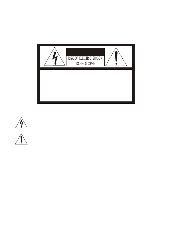
WARNINGS AND CAUTIONS:
CAUTION:
CAUTIONCAUTION
CAUTION: TO REDUCE THE RISK OF ELECTRIC SHOCK,
DO NOT REMOVE COVER(OR BACK).
NO USER-SERVICEABLE PARTS INSIDE.
REFER SERVICING TO QUALIFIED SERVICE PERSONNEL.
EXPLANATION OF GRAPHICAL SYMBOLS
The lightning flash with arrowhead symbol, within an equilateral triangle, is
intended to alert the user to the presence of uninsulated "dangerous voltage"
within the product's enclosure that may be of sufficient magnitude to constitute a
risk of electric shock to persons.
The exclamation point within an equilateral triangle is intended to alert the user to
the presence of important operating and maintenance (servicing) instructions in the
literature accompanying the product.
Should any liquid or solid object fall into the cabinet,
unplug the unit and have it checked by the qualified
personnel before operating it any further.
Unplug the unit from the wall oulet if it is not going to
be used for several days or more. To disconnect the
cord, pull it out by the plug. Never pull the cord itself.
Allow adequate air circulation to prevent internal heat
build-up. Do not place the unit on surfaces (rugs,
blankets, etc.) or near materials(curtains, draperies)
that may block the ventilation holes.
Height and vertical linearity controls located at the
rear panel are for special adjustments by qualified
personnel only.
Do not install the unit in an extremely hot or
humid place or in a place subject to excessive
dust, mechanical vibration.
The unit is not designed to be waterproof.
Exposure to rain or water may damage the unit.
Clean the unit with a slightly damp soft cloth.
Use a mild household detergent. Never use
strong solvents such as thinner or benzine as
they might damage the finish of the unit.
Retain the original carton and packing
materials for safe transport of this unit in the
future.
Safety ----------------------------------------- Installation -----------------------------------
Cleaning --------------------------------------
PRECAUTIONS
TO REDUCE THE RISK OF FIRE OR ELECTRIC SHOCK, DO NOT EXPOSE THIS PRODUCT TO RAIN OR
MOISTURE. DO NOT INSERT ANY METALLIC OBJECTS THROUGH THE VENTILATION GRILLS OR
OTHER OPENINGS ON THE EQUIPMENT.
Page 3
iii
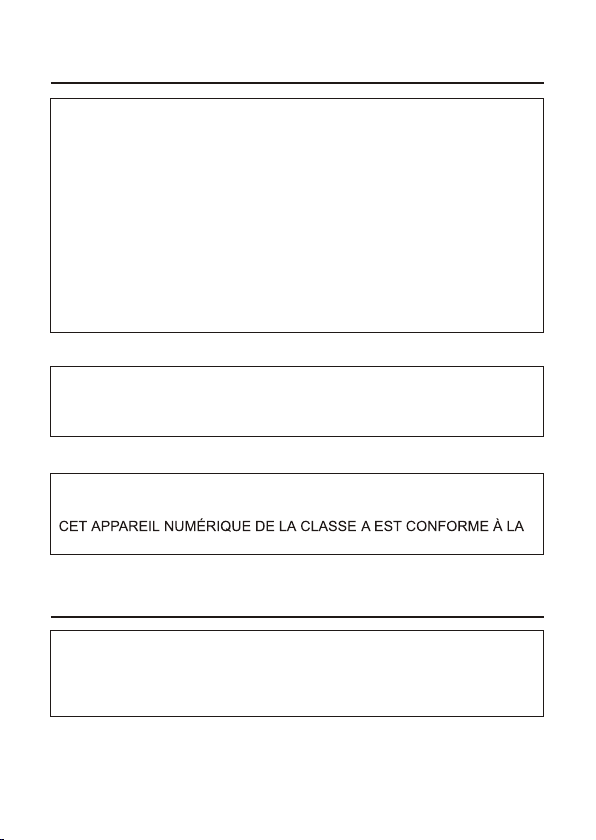
FCC INFORMATION : THIS EQUIPMENT HAS BEEN TESTED
AND FOUND TO COMPLY WITH THE LIMITS FOR A CLASS A DIGITAL
DEVICE, PURSUANT TO PART 15 OF THE FCC RULES. THESE
LIMITS ARE DESIGNED TO PROVIDE REASONABLE PROTECTION
AGAINST HARMFUL INTERFERENCE WHEN THE EQUIPMENT IS
OPERATED IN A COMMERCIAL ENVIRONMENT. THIS EQUIPMENT
GENERATES, USES, AND CAN RADIATE RADIO FREQUENCY
ENERGY AND IF NOT INSTALLED AND USED IN ACCORDANCE WITH
THE INSTRUCTION MANUAL, MAY CAUSE HARMFUL INTERFERENCE
TO RADIO COMMUNICATIONS. OPERATION OF THIS EQUIPMENT IN
A RESIDENTIAL AREA IS LIKELY TO CAUSE HARMFUL
INTERFERENCE IN WHICH CASE THE USER WILL BE REQUIRED TO
CORRECT THE INTERFERENCE AT HIS OWN EXPENSE.
CAUTION : CHANGES OR MODIFICATIONS NOT EXPRESSLY
APPROVED BY THE PARTY RESPONSIBLE FOR COMPLIANCE
COULD VOID THE USER'S AUTHORITY TO OPERATE THE EQUIPMENT.
THIS CLASS A DIGITAL APPARATUS COMPLIES WITH CANADIAN
ICES-003.
NORME NMB-003 DU CANADA.
WARNING
This is a Class A product. In a domestic environment this product
may cause radio interference in which case the user may be required
to take adequate measures.
CE COMPLIANCE STATEMENT
FCC COMPLIANCE STATEMENT
Page 4

iv
1. Read these instructions.
2. Keep these instructions.
3. Heed all warnings.
4. Follow all instructions.
5. Do not use this apparatus near water.
6. Clean only with dry cloth.
7. Do not block any ventilation openings. Install in accordance with the
manufacturer's instructions.
8. Do not install near any heat sources such as radiators, heat
registers, stoves, or other apparatus (including amplifiers) that
product heat..
9. Do not defeat the safety purpose of the polarized or grounding-type
Plug. A polarized plug has two blades with one wider than the other.
A grounding type plug has two blades and a third grounding prong.
The wide blade or the third prong are provided for your safety. If the
provided plug does not fit into your outlet, consult an electrician for
replacement of the obsolete outlet.
10. Protect the power cord from being walked on or pinched
particularly at plugs, convenience receptacles, and the point where
exit from the apparatus.
11. Only use attachments/accessories specified by the manufacturer.
12. Unplug this apparatus during lightning storms or when unused for
long periods of time.
13. Refer all servicing to qualified service personnel. Servicing is
required when the apparatus has been damaged in any way, such
as power-supply cord or plug is damaged, liquid has been spilled or
objects have fallen into the apparatus, the apparatus has been
exposed to rain or moisture, does not operate normally, or has been
dropped.
14. CAUTION - THESE SERVICING INSTRUCTIONS ARE FOR USE
BY QUALIFIED SERVICE PERSONNEL ONLY. TO REDUCE THE
RISK OF ELECTRIC SHOCK DO NOT PERFORM ANY SERVICING
OTHER THAN THAT CONTAINED IN THE OPERATING
INSTRUCTIONS UNLESS YOU ARE QUALIFIED TO DO SO.
15. Use Certified/Listed Class 2 power source only.
thy
IMPORTANT SAFEGUARDS
Page 5
INTRODUCTION
1
The camera provides high-quality images using SONY 1/3" CCD and digital signal
processing LSIs.
Features:
1/3" Super HADII CCD for an image of high sensitivity
Digital Wide Dynamic Range
Excellent picture quality
560 lines of resolution
0.25 Lux(Color), 0.01 Lux(B/W)@ F1.2 Sensitivity
Auto electronic shutter [1/60(1/50) ~ 1/100,000] and manual electronic shutter modes
OSD (On Screen Display)
Auto and manual white balance modes
Selectable BLC Zone
HSBLC
3D-Digital Noise Reduction
Day&Night (Auto/Manual)
Privacy Zone 8 point, Motion Detection 4 Point
SHARPNESS, D-ZOOM, NEGA/POSI, MIRROR, V FLIP, ROTATION, FREEZE
AGC (Auto Gain Control)
VIDEO OUT(BNC)
Internal/AC line lock
2.6~6mm
Operates in 12VDC or 24VAC
Use Certified / Listed Class 2 power source only.
(Xtended Dynamic Range)
, 4-9mm, 2.8~12mm, 6~50mm D&N Auto Iris Lens.
IMPORTANT : The user of this camera is responsible for checking
and complying with local, state, and federal laws and statutes concerning
the recording and monitoring of audio signals.
CAUTION: Before plugging in, please check the label to make sure you have the proper rating.
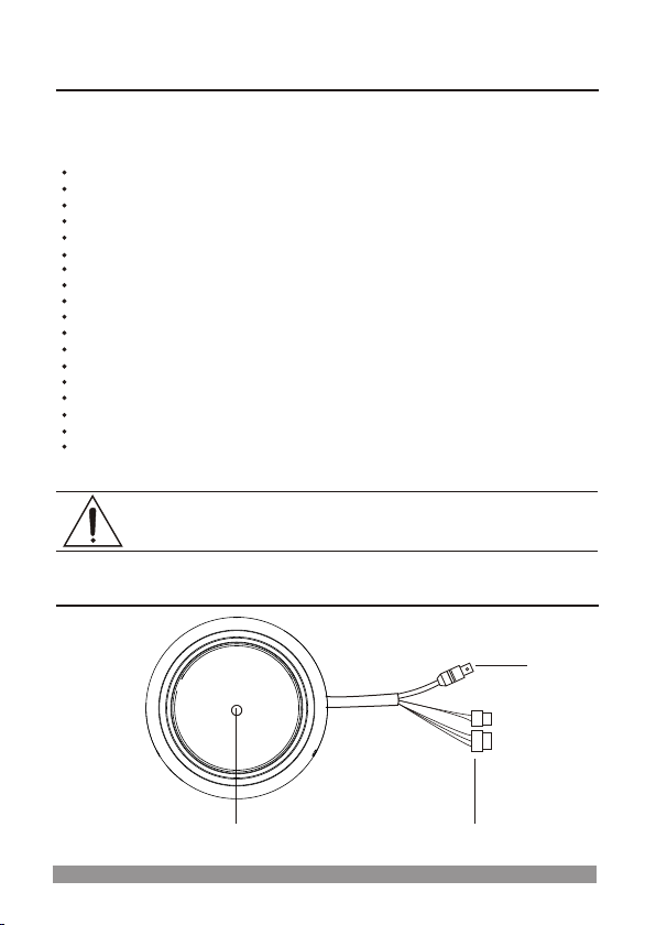
CAMERA CONNECTIONS
1
3
2
1. Lens : Allows a wide area to be monitored.
Page 6

2. Color Lead Wire & Color Display Label
2
3. Power : power source from a DC 12V / AC24V +/- 10%
Use Certified/Listed Class 2 power supply transformer only.
*If use DC 12V / AC24V power adaptor, use the power consumption 5W over.
REMINDER:
Never aim the
camera directly
into the sun.
COLOR
RED
WHITE
YELLOW
GRAY
BLACK
DESCRIPTION
AC24V/DC12V
AC24V/DC12V
ALARM OUT
DN EXT-IN
DN EXT-OUT
GND
BLACK&WHITE
4. Video : BNC connector used to connect the camera to a monitor, switcher, etc.
COLOR
RED
WHITE
YELLOW
GRAY
BLACK
DESCRIPTION
AC24V/DC12V
AC24V/DC12V
ALARM OUT
DN EXT-IN
DN EXT-OUT
GND
BLACK&WHITE
5. DAY&NIGHT I/O Terminals
To select Day/Night mode using external equipment, connect control lines
to the appropriate terminals.
DAY&NIGHT OUTPUT
It is the function that can turn on external IR LED Lamp by detecting the sensitivity on
the AGC level when the D&N mode is set "AUTO" on the OSD menu of the camera.
DAY&NIGHT EXTERNAL INPUT
It is the function that can be switched to DAY Mode or NIGHT Mode by receiving the
D&N on/off signal from external light sensor or IR LED LAMP. When D&N Mode is set
"External" on the OSD menu of the camera.
6. ALARM OUT
Motion detection signals are output through this port. (On High (5V))
DN EXT-OUT
GND
5V/10mA : IR LED ON(NIGHT)
0V : IR LED OFF(DAY)
GND
DN EXT-IN
Open contact : DAY
Close contact : NIGHT
Page 7

INSTALLATION
Dome body
Liner
1. Make mounting holes and cable hole in the place (ceiling or wall) to which this dome
camera is installed using the Drilling guide label.
PACKAGE CONTENTS
The package contains the following.
Camera in Housing 1
Instruction Manual (This Document) 1
Accessory Kit for Installing 1
1Drilling guide label
3
2.
Push the liner on the sides where the patterns are put in the teeth of a
comb and pull it out.
To remove dome cover, turn the dome body counterclockwise until locators reach end of
travel and pull off.
Screw Tapping (M6)
Drilling Guide Label
Plastic anchor
Drilling Po
sitio
n(P
A5)
WALL
Page 8

4
3. Attach the housing to the ceiling using suitable fasteners, M6x35 tapping screws are
supplied only use if they are suitable. Turn the housing to right direction about 16 degrees
to lock in place.
4. The assembly of the dome body and liner is in reverse order of disassembly.
Finally, lock dome body with locking screw(M3X5) from the accessory kit.
OPERATING CAMERA
Enter Button
Up
Down
Left
Right
Spot Video Out
1
2
3
4
5
6
1
2
3
4
5
6
The housing can also be mounted
on a 4s electrical box.
MOUNTING HOUSING TO
AN ELECTRICAL BACK BOX
Electrical box
Torx screws
UNC 8-32 x 0.75
Rubber
Washers(4x)
Page 9

5
STRUCTURE OF THE SETUP MENU
<SETUP>
1.LENS
2.EXPOSURE
3.WHITE BAL
4.DAY NIGHT
5.3DNR
6.SPECIAL
7.ADJUST
8.RESET
9.EXIT
<LENS>
DC
<EXPOSURE>
SHUTTER
BRIGHTNESS
AGC
SENSE-UP
BLC
D-WDR
RETURN
<WHITE BAL> <DAY NIGHT>
AUTO
EXT
B/W
COLOR
<3DNR>
LEVEL
RETURN
<SPECIAL>
CAM TITLE
D-EFFECT
MOTION
PRIVACY
SYNC
LANGUAGE
RETURN
<ADJUST>
SHARPNESS
BLUE
RED
RETURN
<RESET>
FACTORY
RETURN
AWB
AWC -> SET
MANUAL
INDOOR
OUTDOOR
ATW
Page 10

This function is used to adjust the brightness of the screen.
1. When the SETUP menu is displayed on the screen, please position the arrow to point to
'LENS' by using the UP and DOWN buttons.
2. Please select the type of the lens you wish to use by pressing the LEFT or RIGHT button.
LENS (Selection)
1. LENS DC
2. EXPOSURE
3. WHITE BAL AWB
4. DAY NIGHT AUTO
5. 3DNR ON
6. SPECIAL
7. ADJUST
8. RESET
9. EXIT
►
LENS
BRIGHTNESS IIIIIIIIIIIIIIIIII 50
RETURN RET
►
Note The brightness of the screen can be adjusted in DC mode.
The brightness can be adjusted within the range of 0 ~ 100.
The optimum level of brightness for the user can be achieved by adjustment.
EXPOSURE
1. LENS DC
2. EXPOSURE
3. WHITE BAL AWB
4. DAY NIGHT AUTO
5. 3DNR ON
6. SPECIAL
7. ADJUST
8. RESET
9. EXIT
►
EXPOSURE
SHUTTER 1/60
BRIGHTNESS IIIIIIIIIIIIIIIIII 50
AGC HIGH
SENSE-UP AUTO
BLC BLC
D-WDR OFF
RETURN RET
►
The EXPOSURE menu is used to set the automatic light control method for this camera.
(Xtended Dynamic Range)
1) SHUTTER Select the shutter mode.(1/60(50), FLK~ 1/100,000 sec, x2 ~ x256)
Can be changed while in shutter mode.
2) BRIGHTNESS Adjust BRIGHTNESS level (0 ~ 100)
Can be adjusted while in manual lens mode.
3) AGC Auto gain control (OFF / LOW / MIDDLE / HIGH)
4) SENSE-UP Use under very low light condition for full color surveillance.
Select maximum Low-Shutter value. (x2 ~ x256)
5) BLC Sharpens subjects with backlight.(OFF / BLC / HBLC)
6) D-WDR Digital Wide dynamic range
OFF / INDOOR / OUTDOOR
6
BLC
GAIN MIDDLE
DEFAULT
LEFT/RIGHT IIIIIIIIIIIIIIIIII 2
WIDTH IIIIIIIIIIIIIIIIII 4
TOP/BOTTOM IIIIIIIIIIIIIIIIII 3
HEIGHT IIIIIIIIIIIIIIIIII 3
RETURN RET
►
<BLC MODE>
Page 11

7
The screen color can be adjusted by using the WHITE BALANCE function.
1) AWB Wide range auto white balance mode.
2) AWC -> SET Please press the ENTER button while the camera is directed
at a piece of while paper to obtain the optimum state under
current illumination. if the environment including the light source
is changed, you have to adjust the while balance again.
3) MANUAL Manual mode. User can change R and B Gain manually.
O
4) INDOOR Set the color temperature to 3200 K
O
5) OUTDOOR Set the color temperature to 6300 K
O O
6) ATW Set the color temperature 2500 K to 9500 K
WHITE BAL
The DAY/NIGHT menu is used to configure the day and night related setting for this camera.
This camera can turn the IR(infrared)filter on or off.
Mode : AUTO / EXT / B/W / COLOR
DAY NIGHT
1. LENS DC
2. EXPOSURE
3. WHITE BAL AWB
4. DAY NIGHT AUTO
5. 3DNR ON
6. SPECIAL
7. ADJUST
8. RESET
9. EXIT
►
DAY NIGHT AUTO
DELAY IIIIIIIIIIIIIIIIII 5
S-LEVEL IIIIIIIIIIIIIIIIII 50
E-LEVEL IIIIIIIIIIIIIIIIII 30
RETURN RET
►
1. LENS DC
2. EXPOSURE
3. WHITE BAL AWB
4. DAY NIGHT B/W
5. 3DNR ON
6. SPECIAL
7. ADJUST
8. RESET
9. EXIT
►
DAY NIGHT B/W
BURST OFF
RETURN RET
►
<DAY/NIGHT AUTO MODE>
<DAY/NIGHT B/W MODE>
1. LENS DC
2. EXPOSURE
3. WHITE BAL MANUAL
4. DAY NIGHT AUTO
5. 3DNR ON
6. SPECIAL
7. ADJUST
8. RESET
9. EXIT
►
<WHITE BAL MANUAL MODE>
WHITE BAL MANUAL
BLUE IIIIIIIIIIIIIIIIII 50
RED IIIIIIIIIIIIIIIIII 50
RETURN RET
►
You can configure the DNR(Digital Noise Reduction) related settings. if you press the Setup
switch when ON is selected in 3DNR, the corresponding screen appears.
3DNR (Digital Noise Reduction)
Page 12

8
1) CAM TITLE
2) D-EFFECT
FREEZE Select the real or still mode.
MIRROR Reverse the screen in 3 modes selection.
(OFF / MIRROR / V FLIP / ROTATION)
D-ZOOM D-Zoom (x2~x32) / Adjust PAN / TITL
GAMMA Adjust the luminance (0.05~1.00)
NEGA / POSI Select the negative or positive mode.
3) MOTION
AREA SELECT Select MD area number.
AREA DISPLAY Select MD ON/OFF
LEFT/RIGHT Adjust the location of the MD area with boundary LEFT and
RIGHT.
WIDTH Adjust width of MD area
TOP/BOTTOM Adjust the location of the MD area with boundary TOP
and BOTTOM
HEIGHT Adjust height of MD area
SENSITIVITY Adjust sensitivity of MD area.(0~40)
MOTION VIEW The screen displays with green dots. When a motion is detected
in the selected area, the green dots are displayed on the screen.
A. CAM TITLE
B. Character Table
C. Command Line
← : Move to left
→ : Move to right
CLR : Erase all characters
POS : Move the position of title
END : Save and End
SPECIAL
1. LENS DC
2. EXPOSURE
3. WHITE BAL AWB
4. DAY NIGHT AUTO
5. 3DNR ON
6. SPECIAL
7. ADJUST
8. RESET
9. EXIT
►
3DNR
LEVEL IIIIIIIIIIIIIIIIII 50
RETURN RET
►
1. LENS DC
2. EXPOSURE
3. WHITE BAL AWB
4. DAY NIGHT AUTO
5. 3DNR ON
6. SPECIAL
7. ADJUST
8. RESET
9. EXIT
►
SPECIAL
1.CAM TITLE ON
2.D-EFFECT
3.MOTION ON
4.PRIVACY OFF
5. SYNC INT
6.LANGUAGE ENGLISH
7.RETURN RET
►
MOTION
AREA SELECT AREA1
AREA DISPLAY ON
LEFT/RIGHT IIIIIIIIIIIIIIIIII 8
WIDTH IIIIIIIIIIIIIIIIII 32
TOP/BOTTOM IIIIIIIIIIIIIIIIII 4
HEIGHT IIIIIIIIIIIIIIIIII 24
SENSITIVITY IIIIIIIIIIIIIIIIII 40
MOTION VIEW OFF
►
A
B
C
CAM TITLE
01 2 345 6 78 9
AB C DEF G HI J K
LM N OPQ R ST U V
WX Y Z ►→ ← ↑↓( )
‾– _ ▌ / = & : ~ ‚ "
←→ CLR POS END
Page 13

9
1) FACTORY Returns to the level which was set by the manufacturer for
shipment.
RESET
EXIT
1) EXIT Saves all the setting menus and then exits.
1) SHARPNESS Can be adjusted SHARPNESS of outlines.(0~31)
2) BLUE Adjust B-GAIN value.(0~100)
3) RED Adjust R-GAIN value.(0~100)
ADJUST
4) PRIVACY
AREA SELECT Select MASK area number.
AREA DISPLAY Select MASK ON/OFF
LEFT/RIGHT Adjust the location of the MASK area with boundary LEFT
and RIGHT
WIDTH Adjust width of MASK area
TOP/BOTTOM Adjust the location of the MASK area with boundary
TOP and BOTTOM.
HEIGHT Adjust height of MASK area
COLOR Select MASK color. (0~15)
5) SYNC Select Internal or Line Lock mode.
INT This mode is necessary for using the internal synchronization.
L/L This mode is necessary for the operation of multi camera because
it synchronizes the camera phase by using the external signal
(AC Signal).
PHASE Sync phase is adjustable in line lock mode.
6) LANGUAGE You can change the OSD language using the LEFT/RIGHT
Setup switch.
1. LENS DC
2. EXPOSURE
3. WHITE BAL AWB
4. DAY NIGHT AUTO
5. 3DNR ON
6. SPECIAL
7. ADJUST
8. RESET
9. EXIT
►
SPECIAL
1.CAM TITLE ON
2.D-EFFECT
3.MOTION OFF
4.PRIVACY ON
5. SYNC INT
6.LANGUAGE ENGLISH
7.RETURN RET
►
PRIVACY
AREA SELECT AREA1
AREA DISPLAY ON
LEFT/RIGHT IIIIIIIIIIIIIIIIII 8
WIDTH IIIIIIIIIIIIIIIIII 20
TOP/BOTTOM IIIIIIIIIIIIIIIIII 10
HEIGHT IIIIIIIIIIIIIIIIII 35
COLOR IIIIIIIIIIIIIIIIII 0
RETURN RET
►
<PRIVACY MODE>
Page 14

DC AUTO IRIS LENS
Image Size
Focal Length
Aperture Ratio
Angular
Field of View
4-9mm
DIAGONAL
o
4mm : 92.4
o
9mm : 39.2
4.0-9.0mm 5%
1 : 1.6 5%
Black Control ( - )
White Control ( + )
Red Drive ( + )
Green Drive ( - )
LENS
10
1/3" CCD
6-50mm
DIAGONAL
o
6mm : 58.6
o
50mm : 7.1
6.0-50mm 5%
1 : 1.6 6.9%
1/3" CCD
Yellow
Brown IR filter out ( + )
LENS
Brown
Red
Yellow
Orange
LENS
Damper ( - )
Damper ( + )
Drive ( + )
Drive ( - )
o
2.8mm : 119.9
o
12mm : 28.8
2.8-12mm 5%
1 : 1.4 5%
1/3" CCD
2.6~6mm
1/3" CCD
2.6-6.0mm 5%
1 : 1.6 5%
DIAGONAL
o
2.6mm : 134.6
o
6mm : 59.2
LENS ADJUSTMENT (OPTIONAL VARIFOCAL LENS)
Field of view: Adjust setting from Telephoto (T)
to wide (W) field of View.
Focus: Adjust lens focus from near
(N) to infinity ( ).
N
T
W
Adjust Focus
Adjust Angular Field View
2.8~12mm
(Aspherical )
Page 15

Power source
Power consumption
Image sensor
Total pixels
Scanning system
Scanning frequency
Sync. system
Resolution
Min. illumination
Video output
Power input
SENSE-UP
(Low Shutter Speed)
Lens mount
1/3" SONY Super HADII CCD
2:1 interlace
15.734KHz(H) x 59.94Hz(V)
Internal / Line lock
560 TV lines
Color(0.25 Lux), B/W(0.01 Lux) (SENS UP : OFF)
50dB (AGC OFF)
On(Indoor / Outdoor) / Off
On( Low / Middle / High) / Off
795(H) x 596(V)
Terminal block
2.6~6mm, 4-9mm, 2.8~12mm, 6~50mm D/N Vari-focal (DC AI)
NTSC
3.0 Watts
811(H) x 508(V)
MODEL
S/N ratio
BLC
(Back Light Composite)
D-WDR
(Digital Wide Dynamic Range)
Day & Night (True D/N)
PM (Privacy Masking)
Electronic Shutter Speed
Flip
Effect
AGC (Auto Gain Control)
Setup Method
OSD Language
F
U
N
C
T
I
O
N
SPECIFICATIONS
Power
15.625KHz(H) x 50Hz(V)
Connector
&
etc.
PAL
Sharpness
Video output
Operating temperature
Operating humidity
1.0 Vp-p (75 ohm, composite)
Auto / Off (Selectable limit 2X ~ 256X)
On / Off (8 Programmable zone)
AWB / ATW / AWC / Manual / Indoor / Outdoor
Auto / Flickerless / Manual (25 6X, 1/60 ~ 1/ 100,000)
On / Off (Level adjustable)
Fixed mount
0 ~ 96% (non-condencing)
General
11
5
On / Off (Adjustable Gain)
WB (White Balance)
Color / B/W / Auto (Filter auto change) / EXT
DNR
(Digital Noise Reduction)
BLC / HSBLC / OFF Adjustable Size & Gain
MD (Motion Detection)
On / Off (4 Programmable zone)
Horizontal / Vertical / Rotate
OSD setup menu
D-Zoom x32(Pan / Tilt) / Nega / Freeze
English / Korean / Japanese
External I/O Terminals
Lens
External Dimension
Weight
BNC connector
Alarm output, Day & Night input / output
146 x 113 mm (Bubble Diameter Ø100)
450g
Page 16

50302581A
Super High Resolution
Day & Night Color Camera
EXTERNAL DIMENSION
Dimensions
Window Size
Cable Entry
Weight - Unit:
Shipping:
Uni t: mm
0.1 in. (2.5mm thick),
impact-resistant P.C (LEXAN)
3.93 in. (10cm) diameter
One 1" opening holes
0.99 lb. (0.45kg)
1.41 lb. (0.64 kg)
145.6
100 (Inner)
113
59
 Loading...