

Page 1

Page 2

Page 3
1
About This Document
This document contains instructions for DVR configuration and operation.
Package Contents
The package contains the following:
Digital Video Recorder
Power Cord
Quick User Guide (This Document)
Software CD (User’s Manual included)
Rack-mount Kit
Assembly Screws for Adding Hard Disk Drives
SATA Cables
Infrared Remote Control
USB Mouse
Notice
Specifications are subject to change without prior notice.
The information contained herein is to be considered for reference only.
The software included in this product contains some Open Sources. You may obtain the complete corresponding
source code from us. See the Open Source Guide on the software CD (OpenSourceGuide\OpenSourceGuide.pdf).
Warning
WARNING
RISK OF ELECTRIC SHOCK
DO NOT OPEN
WARNING: TO REDUCE THE RISK OF ELECTRIC SHOCK,
DO NOT REMOVE COVER (OR BACK).
NO USER-SERVICEABLE PARTS INSIDE.
REFER SERVICING TO QUALIFIED SERVICE PERSONNEL.
The lightning flash with arrowhead symbol, within an equilateral triangle, is intended to alert the user
to the presence of uninsulated "dangerous voltage" within the product’s enclosure that may be of
sufficient magnitude to constitute a risk of electric shock.
The exclamation point within an equilateral triangle is intended to alert the user to the presence of
important operating and maintenance (servicing) instructions in the literature accompanying the appliance.
Page 4

2
Important Safeguards
1. Read Instructions
All the safety and operating instructions should be read before the appliance is operated.
2. Retain Instructions
The safety and operating instructions should be retained for future reference.
3. Cleaning
Unplug this equipment from the wall outlet before cleaning it. Do not use liquid aerosol cleaners. Use a damp
soft cloth for cleaning.
4. Attachments
Never add any attachments and/or equipment without the approval of the manufacturer as such additions may
result in the risk of fire, electric shock or other personal injury.
5. Water and/or Moisture
Do not use this equipment near water or in contact with water.
6. Ventilation
Place this equipment only in an upright position. This equipment has an open-frame Switching Mode Power
Supply (SMPS), which can cause a fire or electric shock if anything is inserted through the ventilation holes on
the side of the equipment.
7. Accessories
Do not place this equipment on an unstable cart, stand or table. The equipment may fall, causing serious injury
to a child or adult, and serious damage to the equipment. Wall or shelf mounting should follow the manufacturer's
instructions, and should use a mounting kit approved by the manufacturer.
This equipment and cart combination should be moved with care. Quick stops, excessive force, and uneven
surfaces may cause the equipment and cart combination to overturn.
8. Power Sources
This equipment should be operated only from the type of power source indicated on the marking label. If you
are not sure of the type of power, please consult your equipment dealer or local power company.
9. Power Cords
Operator or installer must remove power and TNV connections before handling the equipment.
10. Lightning
For added protection for this equipment during a lightning storm, or when it is left unattended and unused for
long periods of time, unplug it from the wall outlet and disconnect the antenna or cable system. This will prevent
damage to the equipment due to lightning and power-line surges.
11. Overloading
Do not overload wall outlets and extension cords as this can result in the risk of fire or electric shock.
12. Objects and Liquids
Never push objects of any kind through openings of this equipment as they may touch dangerous voltage points
or short out parts that could result in a fire or electric shock. Never spill liquid of any kind on the equipment.
13. Servicing
Do not attempt to service this equipment yourself. Refer all servicing to qualified service personnel.
14. Damage requiring Service
Unplug this equipment from the wall outlet and refer servicing to qualified service personnel under the following
conditions:
A. When the power-supply cord or the plug has been damaged.
B. If liquid is spilled, or objects have fallen into the equipment.
C. If the equipment has been exposed to rain or water.
D. If the equipment does not operate normally by following the operating instructions, adjust only those controls
that are covered by the operating instructions as an improper adjustment of other controls may result in damage
and will often require extensive work by a qualified technician to restore the equipment to its normal operation.
E. If the equipment has been dropped, or the cabinet damaged.
F. When the equipment exhibits a distinct change in performance ─ this indicates a need for service.
Page 5
3
15. Replacement Parts
When replacement parts are required, be sure the service technician has used replacement parts specified by the
manufacturer or that have the same characteristics as the original part. Unauthorized substitutions may result
in fire, electric shock or other hazards.
16. Safety Check
Upon completion of any service or repairs to this equipment, ask the service technician to perform safety checks
to determine that the equipment is in proper operating condition.
17. Field Installation
This installation should be made by a qualified service person and should conform to all local codes.
18. Correct Batteries
Warning: Risk of explosion if battery is replaced by an incorrect type. Dispose of used batteries according to
the instructions.
19. Tmra
A manufacturer’s maximum recommended ambient temperature (Tmra) for the equipment must be specified
so that the customer and installer may determine a suitable maximum operating environment for the equipment.
20. Elevated Operating Ambient Temperature
If installed in a closed or multi-unit rack assembly, the operating ambient temperature of the rack environment
may be greater than room ambient. Therefore, consideration should be given to installing the equipment in an
environment compatible with the manufacturer’s maximum rated ambient temperature (Tmra).
21. Reduced Air Flow
Installation of the equipment in the rack should be such that the amount of airflow required for safe operation
of the equipment is not compromised.
22. Mechanical Loading
Mounting of the equipment in the rack should be such that a hazardous condition is not caused by uneven mechanical
loading.
23. Circuit Overloading
Consideration should be given to connection of the equipment to supply circuit and the effect that overloading
of circuits might have on over current protection and supply wiring. Appropriate consideration of equipment
nameplate ratings should be used when addressing this concern.
24. Reliable Earthing (Grounding)
Reliable grounding of rack mounted equipment should be maintained. Particular attention should be given to
supply connections other than direct connections to the branch circuit (e.g., use of power strips).
Disposal
WEEE (Waste Electrical & Electronic Equipment)
Correct Disposal of This Product
(Applicable in the European Union and other European countries with separate collection systems)
This marking shown on the product or its literature, indicates that it should not be disposed with other household wastes at the
end of its working life. To prevent possible harm to the environment or human health from uncontrolled waste disposal, please
separate this from other types of wastes and recycle it responsibly to promote the sustainable reuse of material resources.
Household users should contact either the retailer where they purchased this product, or their local government office, for details
of where and how they can take this item for environmentally safe recycling.
Business users should contact their supplier and check the terms and conditions of the purchase contract. This product should
not be mixed with other commercial wastes for disposal.
Page 6

4
Specifications
Video
Signal Format
NTSC or PAL (Auto Detect)
Video Input
Composite: 16 looping inputs, 1 Vp-p, auto-terminating, 75 Ohms
Monitor Outputs
HDMI: 1 HDMI
VGA: 1
SPOT: 1 BNC, 1 Vp-p, 75 Ohms
Video Resolution
HDMI: 1920x1080, 1440x900, 1280x1024
VGA: 1920x1080, 1440x900, 1280x1024
Composite (SPOT): 720x480 (NTSC), 720x576 (PAL)
Record Speed
480ips (NTSC), 400ips (PAL) @ D1 (Real-time)
Playback Speed
480ips (NTSC), 400ips (PAL) @ CIF (Full Duplex)
Inputs/Outputs
Alarm Input
16 terminal, programmable as NC or NO, 2.4V (NC) or 0.3V (NO) threshold,
5VDC
Alarm Output
2 relay output, programmable as NC or NO, 2A@125VAC, 1A@30VDC
Alarm Reset Input
1 TTL, terminal block
Internal Buzzer
80dB at 10cm
Network Connectivity
10/100Mbps, 1Gbps Ethernet (RJ-45)
Audio Input
RCA Input: 4 Line In
Audio Output
RCA Output: 1, Line Out
Text Input
POS Interface, ATM Interface
Connectors
Video Input
Composite: 16 BNC
Video Loop
Composite: 16 BNC (Auto Terminating)
Monitor Output
HDMI: 1 HDMI
VGA: 1 VGA
SPOT (Composite): 1 BNC
Audio In
4 RCA connector
Audio Out
1 RCA connector
Alarm Input/Output
Terminal Blocks
Ethernet Port
RJ-45
eSATA Port
eSATA
RS232 Serial Port
Two-connector terminal block
RS485 Serial Port
Two-connector terminal block
IR Port
1 Remote Control
USB Port
2 (USB 2.0)
Storage
Primary Storage
SATA hard disk drive (up to 4) (up to 3 with an internal DVD RW drive)
Secondary Storage
eSATA hard disk drive, Built-in DVD RW drive, USB hard disk drive or flash drive
General
Dimensions
16.9" (W) x 3.5" (H) x 15.7" (D) (430mm x 88mm x 400mm)
Unit Weight
14.20 lbs. (6.44kg)
Shipping Weight
21.20 lbs. (9.62kg)
Shipping Dimensions
23.2" (W) x 11.4" (H) x 21.3" (D) (590mm x 290mm x 540mm)
Operating Temperature
41°F to 104°F (5°C to 40°C)
Operating Humidity
0% to 90%
Power
100 to 240 VAC, 1.2 – 0.6 A, 60/50Hz
Power Consumption
Max. 70W
Approvals
FCC, UL, CB, CE
Page 7

5
Table of Contents
Installation ........................................................................................................................................ 7
Video Input .................................................................................................................................... 7
Video Loop Through ..................................................................................................................... 7
Audio In/Out .................................................................................................................................. 7
eSATA Port ................................................................................................................................... 8
Alarm Input/Output........................................................................................................................ 8
RS485 Port ................................................................................................................................... 8
RS232 Port ................................................................................................................................... 8
Factory Reset Switch .................................................................................................................... 9
Video Out ...................................................................................................................................... 9
Network Port ................................................................................................................................. 9
Power Cord Connector ................................................................................................................. 9
Configuration .................................................................................................................................. 10
Front Panel Buttons and LEDs ................................................................................................... 10
IR Remote Control ...................................................................................................................... 12
Turning on the Power ................................................................................................................. 12
Shutting down the System .......................................................................................................... 12
Initial Unit Setup.......................................................................................................................... 13
Setup Wizard .............................................................................................................................. 14
Operation ........................................................................................................................................ 18
Live Monitoring ........................................................................................................................... 18
Searching Video ......................................................................................................................... 19
Remote Program ............................................................................................................................ 21
REVO Remote ............................................................................................................................ 21
REVO Remote Pro ..................................................................................................................... 22
REVO Mobile .............................................................................................................................. 23
Page 8

6
Page 9
7
Installation
No special tools are required to install the DVR. Refer to the installation manuals for the other items that make
up part of your system.
Your DVR can be used with either NTSC or PAL equipment.
NOTE: You cannot mix NTSC and PAL equipment. For example you cannot use a PAL camera and an
NTSC monitor.
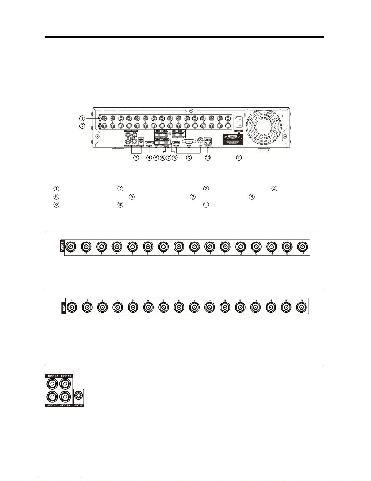
< 16-Channel DVR rear panel >
Video Input Video Loop Through Audio In/Out eSATA Port
Alarm Input/Output RS485 Port RS232 Port Factory Reset Switch
Video Out Network Port Power Cord Connector
Video Input
Connect the coaxial cables from the video sources to the BNC Video In connectors.
Video Loop Through
If you would like to connect your video source to another device, you can use the Loop BNC connectors.
NOTE: The Loop BNC connectors are auto terminated. Do NOT connect a cable to the Loop BNC unless it
is connected to a terminated device because it will cause poor quality video.
Audio In/Out
NOTE: It is the user’s responsibility to determine if local laws and regulations permit recording audio.
The DVR does not have amplified audio output, so you will need a speaker with an amplifier. The
DVR does not have a pre-amplifier for audio input, so the audio input should be from an amplified
source, not directly from a microphone.
Your DVR can record audio from up to four sources. If supported, connect the audio
sources to Audio In 1, Audio In 2, Audio In 3 and Audio In 4 as needed using RCA
jacks. Connect Audio Out to your amplifier.
Page 10
8
eSATA Port
CAUTION: Do NOT connect or disconnect eSATA devices while the DVR power is on. The
DVR must be powered down to connect or disconnect eSATA devices. Power up
eSATA devices so they are ready for operation before powering up the DVR. Power
down eSATA devices after powering down the DVR and then disconnect eSATA
devices.
CAUTION: If the eSATA device is shut down while the device is operating, the DVR system
might not operate normally.
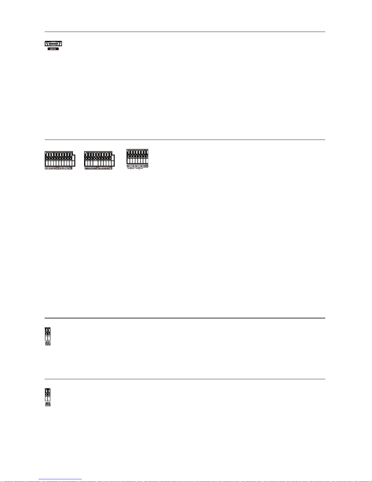
Alarm Input/Output
AI 1 to 16 (Alarm-In): You can use external devices to signal the DVR to react to events. Mechanical or electrical
switches can be wired to the AI (Alarm-In) and GND (Ground) connectors. The threshold voltage of electrical
switches for NC (Normally Closed) is above 2.4V and for NO (Normally Open) is below 0.3V, and should be
stable at least 0.5 seconds to be detected. The voltage range of alarm input is from 0V to 5V.
GND (Ground): Connect the ground side of the Alarm input and/or alarm output to the GND connector.
NOTE: All the connectors marked GND are common.
NC/NO (Relay Alarm Outputs): The DVR can activate external devices such as buzzers or lights. Connect
the device to the C (Common) and NC (Normally Closed) or C and NO (Normally Open) connectors. NC/NO is
a relay output which sinks 2A@125VAC and 1A@30VDC.
ARI (Alarm Reset In): An external signal to the Alarm Reset In can be used to reset both the Alarm Out signal
and the DVR’s internal buzzer. Mechanical or electrical switches can be wired to the ARI (Alarm Reset In) and
GND (Ground) connectors. The threshold voltage is below 0.3V and should be stable at least 0.5 seconds to
be detected. Connect the wires to the ARI and GND connectors.
RS485 Port
RS232 Port
An eSATA port is provided to connect external storage devices for recording video. Connect the
external eSATA hard disk drive (RAID) cable to the eSATA port.
NOTE: To make connections on the Alarm Connector Strip,
press and hold the button and insert the wire in the hole below
the button. After releasing the button, tug gently on the wire
to make certain it is connected. To disconnect a wire, press
and hold the button above the wire and pull out the wire.
The DVR can be controlled remotely by an external device or control system, such as a suitable control
keyboard, using RS485 half-duplex serial communications signals. The RS485 connector can also
be used to control PTZ (pan, tilt, zoom) cameras. Connect RX+/TX+ and RX-/TX- of the control
system to the P+ and N– (respectively) of the DVR.
An RS232 port is provided to connect a remote control keyboard.
Page 11

9
Factory Reset Switch
CAUTION: When using the Factory Reset, you will lose any settings you have saved.
To reset the unit, you will need a straightened paperclip:
1. Turn the DVR off.
2. Turn it on again.
3. While the DVR is initializing, the front panel LEDs will blink. When the front panel LEDs blink, poke
the straightened paperclip into the unlabeled hole to the left of the HDMI connector.
4. Hold the switch until the DVR’s internal buzzer sounds twice.
5. Release the reset switch. All of the DVR’s settings are now at the original settings it had when it left the factory.
Video Out
An HDMI (High-Definition Multimedia Interface) connector is provided so that you can use an HDMI monitor
as your main monitor.
A VGA connector is provided so that you can use a standard, multi-sync computer monitor as your main monitor.
Use the cable supplied with your monitor to connect it to the DVR.
Connect the spot monitor to the SPOT connector as needed.
Network Port
CAUTION: The network connector is not designed to be connected directly with cable or
wire intended for outdoor use.
Power Cord Connector
WARNING: ROUTE POWER CORDS SO THAT THEY ARE NOT A TRIPPING HAZARD.
MAKE CERTAIN THE POWER CORD WILL NOT BE PINCHED OR ABRADED BY
FURNITURE. DO NOT INSTALL POWER CORDS UNDER RUGS OR CARPET.
THE POWER CORD HAS A GROUNDING PIN. IF YOUR POWER OUTLET DOES
NOT HAVE A GROUNDING PIN RECEPTACLE, DO NOT MODIFY THE PLUG.
DO NOT OVERLOAD THE CIRCUIT BY PLUGGING TOO MANY DEVICES IN TO
ONE CIRCUIT.
The DVR has a Factory Reset switch to the left of the HDMI connector on the rear panel.
This switch will only be used on the rare occasions that you want to return all the settings to
the original factory settings.
NOTE: Connect the monitor before the DVR boots so that video can be displayed
on the monitor with the resolution you have set during system setup. If you
want to use both the HDMI and VGA Monitor connectors, one of the monitors
should be connected before the DVR boots, and the other monitor should be
connected after the DVR boots.
The DVR can be networked using the 10Mb/100Mb/1Gb Ethernet connector. Connect a Cat5
cable with an RJ-45 jack to the DVR connector. The DVR can be networked with a computer for
remote monitoring, searching, configuration and software upgrades.
Connect the AC power cord to the DVR and then to a wall outlet.
Page 12

10
Configuration
Front Panel Buttons and LEDs
< 16-Channel DVR front panel >
Camera Buttons HDD LED Alarm Out LED Network LED
Clip Copy LED Power LED Panic Button Alarm Button
Clip Copy Button Zoom/PTZ Button Display/SPOT Button
Group/Sequence Button Playback Mode Button Menu/Cameo Button
Arrow Buttons Play/Pause Button USB Connector
NOTE: The infrared sensor on the DVR is just to the right of the camera buttons. Make certain that nothing
blocks the sensor, or the remote control will not function properly.
When you use wireless communication devices (such as Wi-Fi or Bluetooth) near the DVR, the
remote control might not function properly.
You can also use a USB mouse to navigate through the screens and menus much like you would
on a computer.
Camera Buttons
Pressing the individual camera buttons will cause the selected camera to display full
screen. Buttons 1 to 9 are also used to enter passwords.
In the PTZ mode, pressing the button 1 zooms in the screen and the button 2 zooms out
the screen, pressing the button 3 focuses near and button 4 focuses far, and pressing the
button 5 moves to the preset and button 6 saves the preset.
HDD LED
The HDD LED flickers when the DVR is recording or searching video on the hard disk
drive.
Alarm Out LED
The Alarm Out LED is lit when alarm output or internal buzzer is activated.
Network LED
The Network LED is lit when the unit is connected to a network via Ethernet.
Clip Copy LED
The Clip Copy (Backup) LED is lit when the DVR is clip-copying.
Power LED
The Power LED is lit when the unit is On.
PANIC Button
Pressing the
PANIC button starts panic recoding of all camera channels, and displays on
the screen. Pressing the button again will stop panic recording.
ALARM Button
The
ALARM button has two functions. First, it will reset the DVR’s outputs including
the internal buzzer during an alarm. Second, it will display the event log when you are
in the live monitoring mode unless there is an active alarm. This operation can be user
password protected.
CLIP COPY Button
Pressing the
CLIP COPY (Backup) button allows you to copy video clips.
Page 13
11
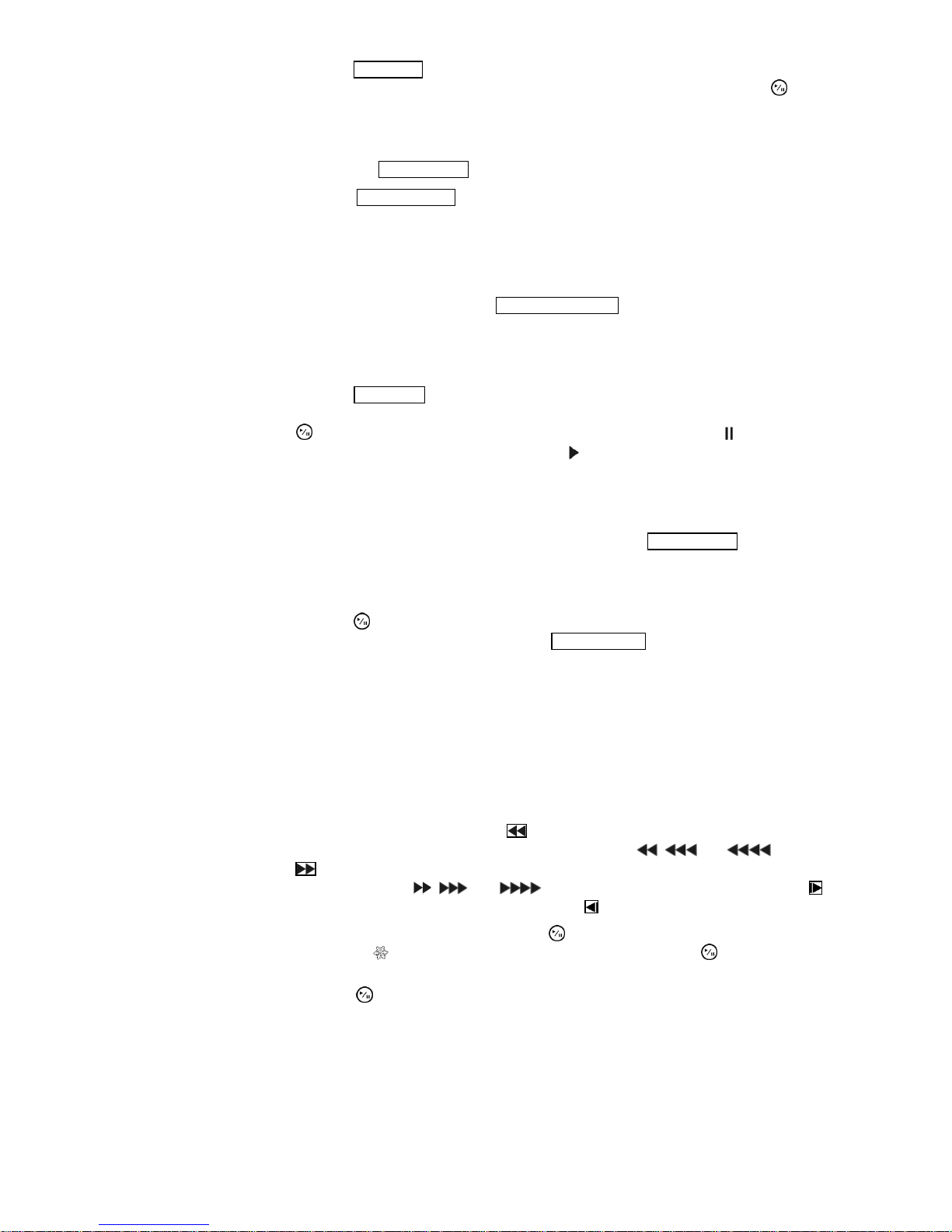
ZOOM/PTZ Button Pressing the
ZOOM/PTZ button zooms in the current image in double on the screen. You
can use the arrow buttons to move the rectangle to another area. Pressing the button
zooms in the image in rectangle.
Pressing and holding the button for three seconds or longer enters the PTZ (Pan/Tilt/Zoom)
mode and the PTZ icon flickers. Pressing the button again exits the PTZ mode. Pressing the
arrow buttons or
MENU/CAMEO button allows you to control properly configured cameras.
DISPLAY/SPOT
Button
Pressing the
DISPLAY/SPOT button toggles between different display formats. The
available formats are: PIP, 2x2, 1+5, 1+7, 3x3 and 4x4 (2x2, 1+5, 1+7, 3x3 and 4x4 on
a Spot Monitor).
Pressing and holding the button for three seconds or longer allows you to select which
cameras will display on the Spot monitor.
GROUP/
SEQUENCE
Button
When in the live mode, pressing the
GROUP/SEQUENCE button changes the screen from the
current camera group to the next camera group, and the screen displays the page number.
Pressing and holding the button for three seconds or longer displays live channels
sequentially.
PLAYBACK Button
Pressing the
PLAYBACK button enters the playback mode, and pressing the button again
exits the playback mode. When entering the playback mode, video is paused. Pressing
the
button plays back video at regular speed. The screen displays when the DVR
is in the Pause mode and the screen displays
when the DVR is playing back video.
When in one of the multi-view formats, pressing this button enters the Triplex mode.
The DVR supports the Triplex function: monitoring, recording and playing back at the
same time.
MENU/CAMEO
Button
In the Live Monitoring mode and Search mode, pressing the
MENU/CAMEO button displays
the menu icons on the right edge of the screen. Pressing the button again hides the menu
icons. During menu setup, pressing the button closes the current menu or setup dialog box.
Pressing and holding the button for three seconds or longer enters the cameo mode.
Pressing the
button exits the Active Cameo mode. Selecting Exit Group Edit in the
cameo menu displayed when pressing the
MENU/CAMEO button also exits the Active
Cameo mode.
Arrow Buttons
These buttons are used to navigate through menus and GUI. You can also use them to
change numbers by highlighting a number in the menu and using the Up and Down arrow
buttons to increase or decrease the number’s value.
These buttons are also used to control Pan and Tilt when in the PTZ mode. When in
the PIP display format, pressing the Up and Down arrow buttons moves the position
of the small screen counter-clockwise and clockwise, and pressing the Left and Right
buttons changes the PIP screen size.
In the playback mode, pressing the button plays video backward at high speed.
Pressing the button again toggles the playback speed from
, and . Pressing
the
button plays video forward at high speed. Pressing the button again toggles the
playback speed from
, and . When in the pause mode, pressing the
button moves to the next image and pressing the
button moves to the previous image.
PLAY/PAUSE
Button
In the live monitoring mode, pressing the
button freezes the current screen and the
screen displays
icon. When in the playback mode, pressing the button plays back
images at regular speed or pauses playing video.
Pressing the button selects a highlighted item or completes an entry that you have
made during system setup.
Page 14
12
IR Remote Control
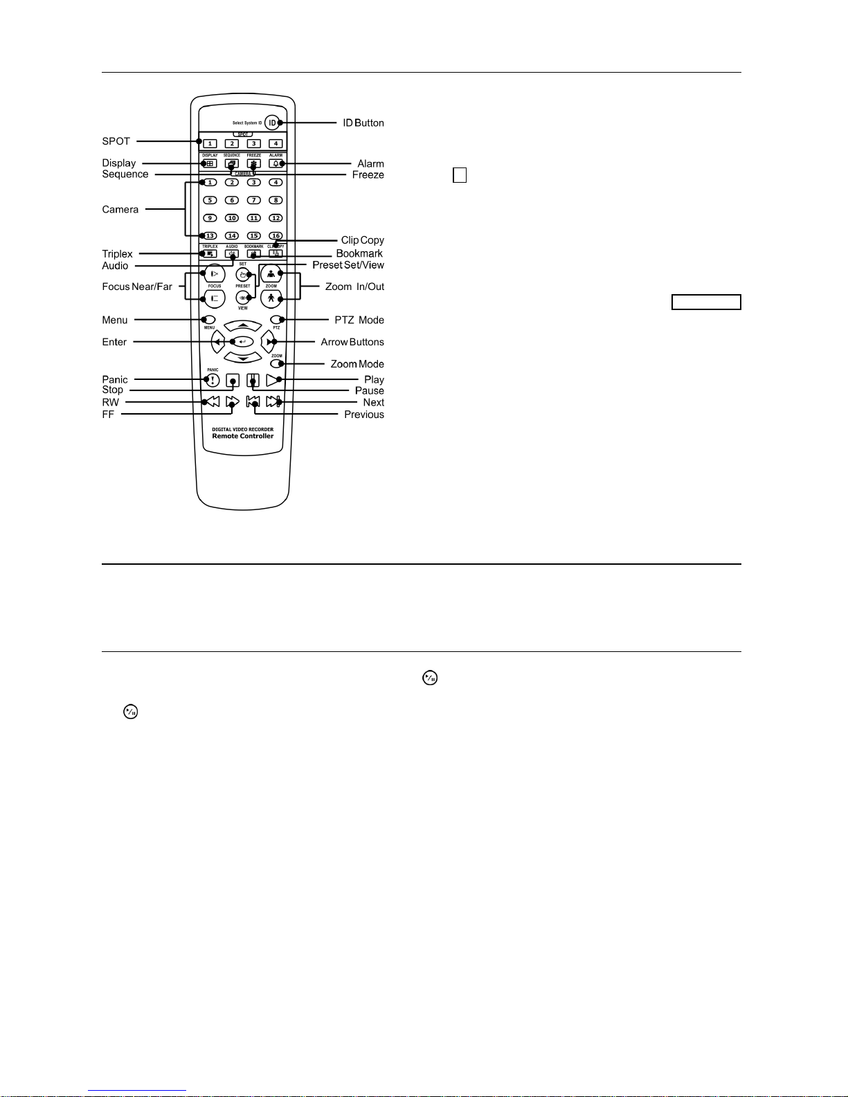
ID Button on Remote Control
If a DVR System ID is set to 0, the infrared remote
control will control that DVR without any additional
operations. If the system ID is 1 to 16, you must to press
the
ID button on the remote control and then press the
number button (1 to 16) in order to control that DVR.
If the System ID of two or more DVRs is set to 0, those
DVRs will react to the infrared remote control at the
same time.
BOOKMARK Button on Remote Control
When in the playback mode, pressing the BOOKMARK
button adds the current playback point to the bookmark
list or moves to the registered bookmark point.
Turning on the Power
Connecting the power cord to the DVR turns on the unit. The unit takes approximately 50 seconds to initialize.
Shutting down the System
Highlight Shutdown in the System menu and press the
button. The Shutdown screen displays asking you to
confirm whether or not you want to shut the system down. After selecting Shutdown in the screen and pressing
the
button, a screen will appear telling you when it is safe to disconnect power.
Page 15
13
Initial Unit Setup
Before using your DVR for the first time, you will want to establish the initial settings. This includes items
such as time and date, display language, camera, remote control, record mode, network and password. Your
DVR can be set up using various screens and dialog boxes.
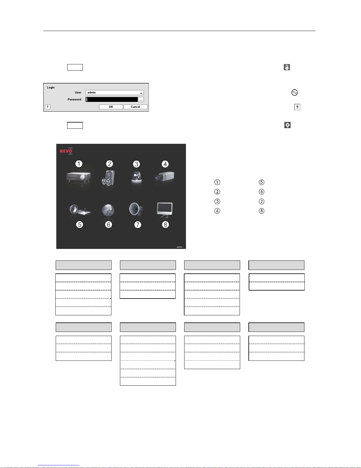
Press the MENU button or move the mouse pointer on the right edge of the screen and then select (Login) in
the Live Monitoring menu to enter the setup screens. The Login screen appears.
Press the MENU button or move the mouse pointer on the right edge of the screen and then select (Setup) in
the Live Monitoring menu.
System Device
Record Network
Event
Notification
Camera Display
System Setup Record Setup Event Setup Camera Setup
General General Motion General
Date/Time Schedule Alarm-In PTZ
User Pre-Event Video Loss
Storage Video Blind
System Event Text-In
Device Setup Network Setup Notification Setup Display Setup
Audio General Callback OSD
Alarm-Out LAN Mail Main Monitor
Remote Control Connection SNS Spot Monitor
RTSP Schedule
REVO Remote Pro
VNC
NOTE: For detailed descriptions of the system setup, refer to the User’s Manual on the software CD.
Select a User and enter the password by pressing the appropriate
combination of Camera number buttons and then the
button.
There is no default password when logging in the admin user for
the first time. If you do not know the password, click the
button
for guidance.
Page 16

14
Setup Wizard
Select the System menu → General → Wizard and press the button. The Wizard setup screen appears.
The Wizard setup guides you through configuring the system for basic operation.
Select either Quick wizard or Network wizard and
select the Next button to start the selected setup
wizard.
If you selected the Quick wizard, selecting the
Next button starts the Quick Setup Wizard.
Date/Time Setup
Date: Set the system date and select the date
format.
Time: Set the system time and select the time
format.
Time Zone: Select your time zone. The Time
Zone can be selected on the map.
Use Daylight Saving Time: Selecting the box
sets the system to use daylight saving time.
Page 17
15
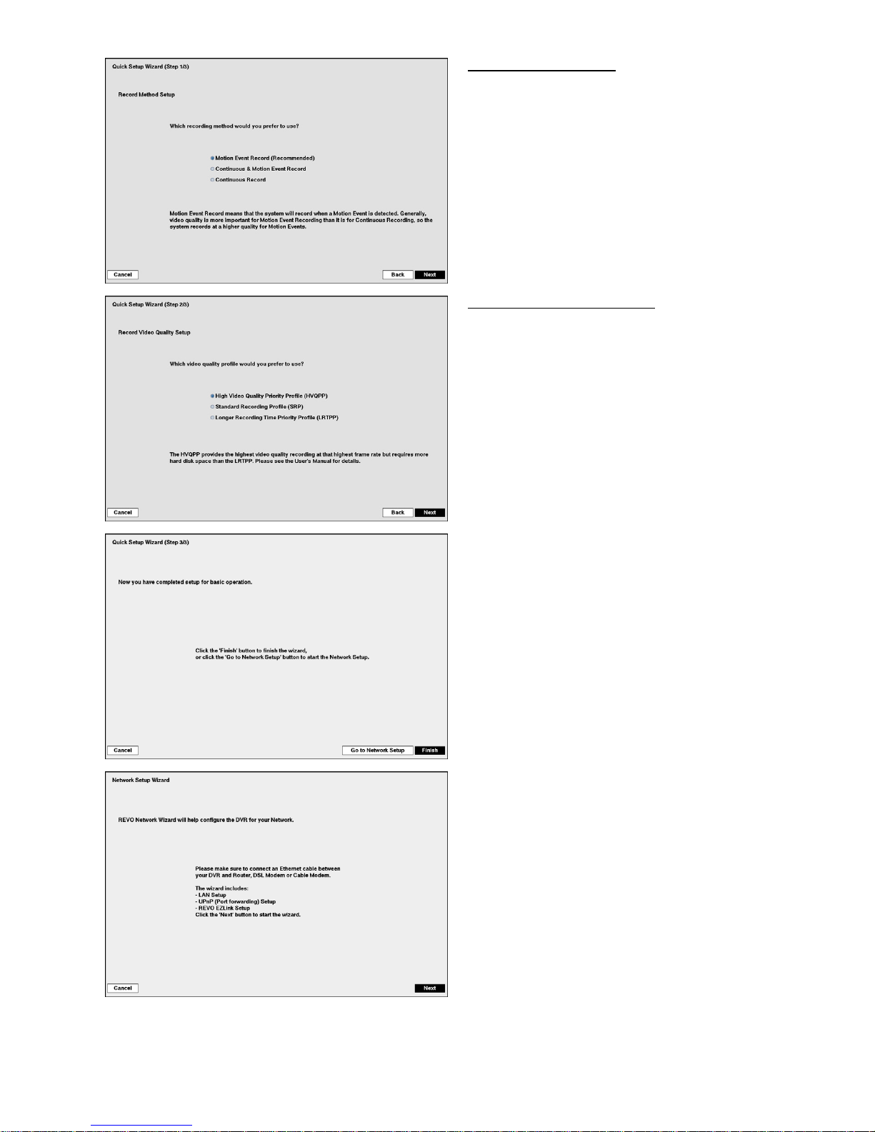
Record Method Setup
Select the desired recording mode from:
– Motion Event Record (Recommended)
– Continuous & Motion Event Record
– Continuous Record
Record Video Quality Setup
Select the desired video quality profile from:
– Higher Video Quality Priority Profile
– Standard Recording Profile
– Longer Recording Time Priority Profile
Select the Finish button to finish the Quick Setup
Wizard and select the Go to Network Setup button
to start the Network Setup.
If you selected the Go to Network Setup, select
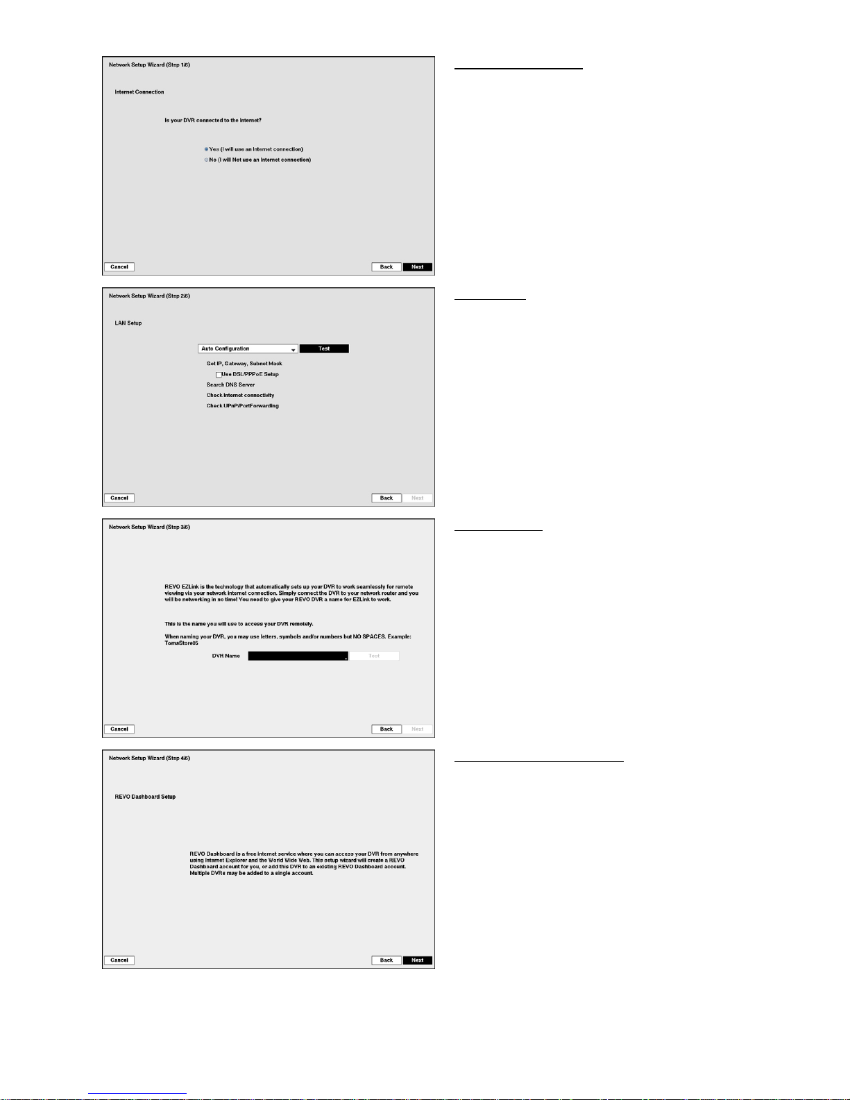
the Next button to start the Network Setup Wizard.
Page 18
16
Internet Connection
Select whether or not your DVR is connected to the
Internet.
LAN Setup
Select between Auto Configuration and Manual
Configuration for network configuration, and
then select the Test button to test the network
configuration you selected.
Use DSL/PPPoE Setup: Selecting the box
allows you to set up the DSL network. Entering
the ID and password for DSL connection is
required.
EZLink Setup
DVR Name: Enter the DVR name to be
registered on the DVRNS (DVR Name Service)
server. The DVR Name you entered should be
checked by selecting Test, otherwise the EZLink
changes will not be saved.
REVO Dashboard Setup I
Select the Next button to start the Dashboard Setup.
Page 19
17
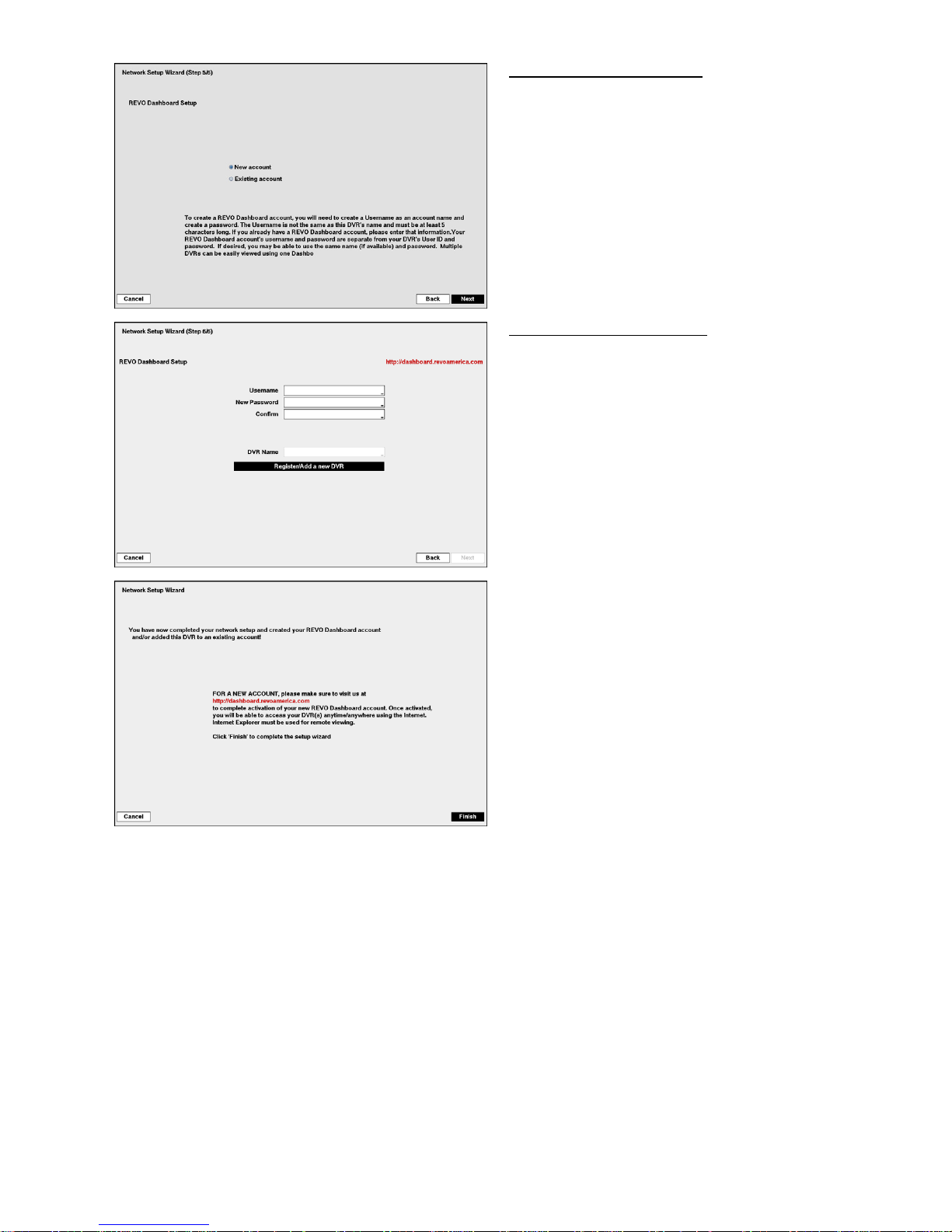
REVO Dashboard Setup II
Select New account if you want to create a new
Dashboard account, and select Existing account
if you want to use your existing Dashboard account.
REVO Dashboard Setup III
Enter the User ID and Password for your Dashboard
account. And then register the DVR you want to
access by entering the DVR name and selecting the
Register/Add a new DVR button.
Select the Finish button to finish the Setup Wizard.
Page 20
18
Operation
Live Monitoring
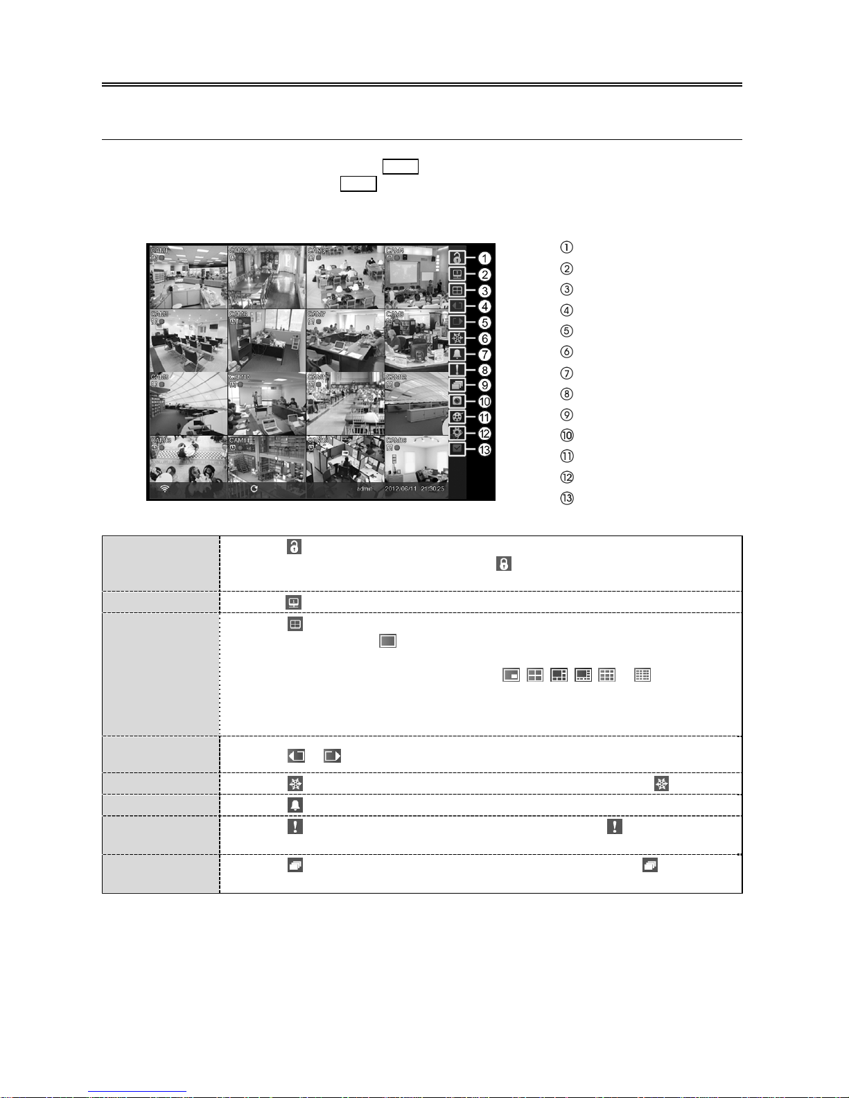
While in the live monitoring mode, pressing the MENU button displays the following Live Monitoring menu on
the right edge of the screen. Pressing the MENU button again hides the menu. You can navigate through menus
and items by pressing the arrow buttons.
Login/Logout
Monitor
Display
Previous Group
Next Group
Freeze
Alarm
Panic
Sequence
Camera Menu
Search
Setup
Status
Login/Logout
Selecting accesses the Login screen, and you will be asked to select a User and enter
the password to log into the system. Selecting
displays the Logout screen asking you
to confirm whether or not you want to log out the current user.
Monitor
Selecting will allow you to select the monitor from Main Monitor and Spot Monitor.
Display
Selecting displays the Display Menu.
Full Screen: Selecting
and choosing the camera number button displays the selected
camera full screen.
PIP, 2x2, 1+5, 1+7, 3x3, 4x4: Selecting
, , , , or displays the
cameras in the selected multiview screen mode.
Camera/Status OSD: Selecting Camera OSD or Status OSD toggles Camera
OSD or Status OSD On and Off.
Previous/Next
Group
Selecting or
moves to the previous or next page.
Freeze
Selecting will freeze the current image on the screen until you select again.
Alarm
Selecting resets the DVR’s outputs including the internal buzzer during an alarm.
Panic
Selecting starts panic recording of all cameras, and selecting again stops panic
recording.
Sequence
Selecting causes the cameras to display sequentially, and selecting again exits
the Sequence mode.
Page 21

19
Camera Menu
Selecting displays the Camera Menu.
PTZ: Selecting PTZ and choosing the camera number allows you to control the selected
camera as long as it has Pan, Tilt and Zoom capabilities.
Zoom: Selecting Zoom and choosing the camera number zooms the current image
of the selected camera on the screen.
Audio: Selecting Audio toggles audio output On and Off.
Color Control: Selecting Color Control and choosing the camera number allows
you to control brightness, contrast, hue and saturation for each camera for the selected
camera.
Edit Group: Selecting Edit Group enters to the Active Cameo mode.
Search
Selecting displays the Search Menu.
All Channels: Selecting All Channels exits the live monitoring mode and enters the
search mode.
Triplex: Selecting Triplex enters the Triplex mode.
Setup
Selecting enters the Main Setup screen.
Status
Selecting will allow you to check the status of the DVR’s system, inputs and storage.
Searching Video
While in the search mode, pressing the MENU button displays the following Search menu on the right edge of
the screen. Pressing the MENU button again hides the menu. You can navigate through menus and items by
pressing the arrow buttons.
Search
Go To
Bookmark
Display
Previous Group
Next Group
Alarm
Panic
Camera Menu
Export
Status
Data Source
Exit
Search
Selecting displays the Search menu.
Event Log Search: Selecting Event Log Search selects video from the event log.
Record Table Search: Selecting Record Table Search selects using a recording table.
Motion Search: Selecting Motion Search selects motion events.
Text-In Search: Selecting Text-In Search selects text input strings.
Go To
Selecting displays the Go to menu.
Go to the First: Selecting Go to the First displays the first recorded image.
Go to the Last: Selecting Go to the Last displays the last recorded image.
Go to the Date/Time: Selecting Go to the Date/Time allows you to set the date
and time you want to search for video.
Bookmark
Selecting adds the current playback point to the bookmark list.
Page 22

20
Display
Selecting displays the Display Menu.
Full Screen: Selecting
and choosing the camera number button displays the selected
camera full screen.
2x2, 1+5, 1+7, 3x3, 4x4: Selecting
, , , or displays the cameras in
the selected multiview screen mode.
Camera/Status OSD: Selecting Camera OSD or Status OSD toggles Camera
OSD or Status OSD On and Off.
Previous/Next
Group
Selecting or
moves to the previous or next page.
Alarm
Selecting resets the DVR’s outputs including the internal buzzer during an alarm.
Panic
Selecting starts panic recording of all cameras, and selecting again stops panic
recording.
Camera Menu
Selecting displays the Camera Menu.
Zoom: Selecting Zoom and choosing the camera number zooms the current playback
image of the selected camera on the screen.
Audio: Selecting Audio toggles audio playback On and Off.
Show/Hide Text-In: Selecting Show Text-In or Hide Text-In shows or hides the
text-in data on the screen if the video was recorded with text-in data.
Edit Group: Selecting Edit Group enters to the Active Cameo mode.
Export
Selecting displays the Export menu.
A–B Backup: Selecting A–B Backup will set the starting point of the video to be
clip copied, and the
icon displays at the bottom-left corner of the screen. Selecting
A–B Backup again will set the ending point of the video to be clip copied and displays
the Backup screen.
Backup: Select Backup, and the Backup screen appears to allow backup setup.
Print: Selecting Print allows you to print a selected image.
Status
Selecting will allow you to check the status of the DVR’s system, inputs and storage.
Data Source
Selecting allows you to select the data source to be searched.
Exit
Selecting exits the search mode and enters the live monitoring mode.
Page 23

21
Remote Program
REVO Remote
REVO Remote allows you to access a remote DVR, monitor live video images and search recorded video using
Internet Explorer web browser anytime from virtually anywhere.
Start Internet Explorer on your local PC. You can run the REVO Remote program by entering the following
information in the address field.
– “http://IP address:port number” (The DVR IP address and the REVO Remote port number (default: 12088)
set in the Network setup screen (REVO Remote tab))
– Or, “http://www.revodvr.com/DVR name” (The DVR name registered on the DVRNS server)
Select between the REMOTE WATCH (Web monitoring) and REMOTE
SEARCH (Web search) modes. Entering ID and PASSWORD and clicking
the [LOGIN] button logs in using the selected mode.
You will need to enter the DVR IP address in the DVR ADDRESS field when
running the REVO Remote program by entering http://www.revodvr.com.
Selecting the Use DVRNS option allows you to enter the DVR name registered
on the DVRNS server instead of the IP address. You must enter the DVRNS
server address and port number in the SETUP setting when selecting the Use
DVRNS option.
Web Monitoring
Web Search
NOTE: For detailed instructions on operating the REVO Remote program, refer to the User’s Manual on
the software CD.
Page 24

22
REVO Remote Pro
REVO Remote Pro program, which is designed to be used with remote digital video recorder, is an integrated
software program that controls system management, video monitoring, video recording and image playback
of multiple remote sites.
CAUTION: If an older version of REVO Remote Pro software is installed on your computer,
a screen appears asking you to upgrade the software. In this case, you are required
to upgrade the software according to the instructions in the screen.
Insert the installation CD and install the REVO Remote Pro software following the instructions.
After installing the REVO Remote Pro software, run the REVO Remote Pro program as follows: Go to the Start
menu on the PC → Click REVO Remote Pro → Enter login information.
NOTE: For detailed instructions on operating the REVO Remote Pro program, refer to the User’s Manual
on the software CD.
Page 25

23
REVO Mobile
REVO Mobile allows you to access remote sites and monitor live video using mobile devices anytime from
virtually anywhere.
CAUTION: This program uses large amounts of data and you are responsible for all data
charges. Please contact your service provider’s customer service to confirm or
add an unlimited data plan.
Android-based mobile devices
1. Run the
Play Store (Google Play) application in the device.
2. Enter REVO Mobile in the search field of the Play Store (Google Play) application.
3. Install the REVO Mobile program and run the program.
4. Run the REVO Mobile program. Push the Menu button of the device and the following default menu is
displayed.
New site: Tap to register DVRs.
Delete site: Tap to delete a DVR. This menu will be available only when there are
DVRs registered.
Settings: Tap to edit the settings or check the information about the REVO Mobile
program.
Push Messages: Tap to display the Push messages.
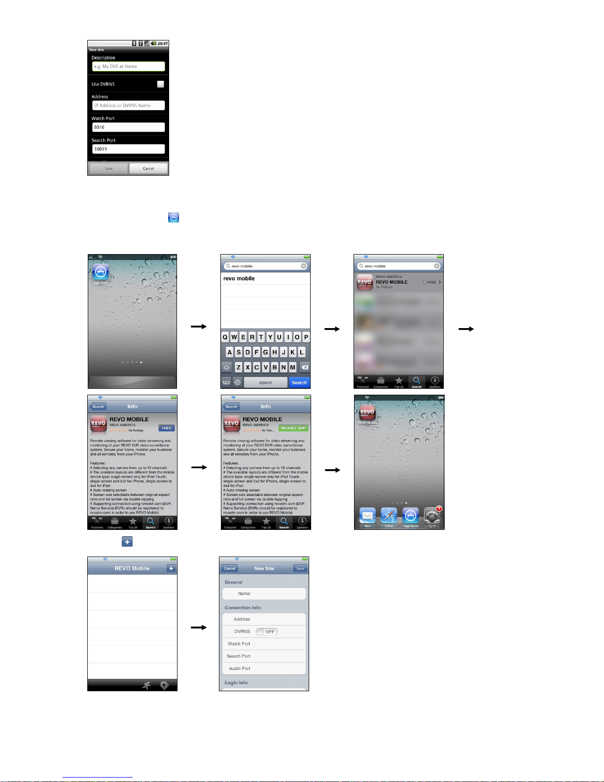
5. Tap the New site button and enter the DVR information to register the DVR.
Page 26
24 V1.0
Description: Enter the DVR name to use in the REVO Mobile program.
Use DVRNS: If the DVR uses the EZLink function, enable the Use DVRNS option.
You can set up the information for the DVRNS server by tapping the Settings button
in the default menu.
Address, Watch Port, Search Port, Audio Port: Enter the IP address and port number
of the DVR. If the DVR uses the EZLink function, check that the Use DVRNS option
is enabled and enter the DVR name registered on the DVRNS server instead of the IP
address. The name you enter should match the name set during the EZLink setup on
the DVR.
User ID, Password: Enter the user ID and password. The user ID and password you
enter should match the user ID and password used to log on to the DVR.
iOS-based mobile devices
1. Run the App Store
application in the device.
2. Enter REVO Mobile in the search field of the App Store application.
3. Install the REVO Mobile program and run the program.
4. Tap the button and enter the DVR information to register the DVR.
General: Enter the DVR name to use in the REVO
Mobile program.
Connection Info: Enter the IP address and port
number of the DVR. If the DVR uses the EZLink
function, enable the DVRNS option and enter the
DVR name registered on the DVRNS server instead
of the IP address. The name you enter should match
the name set during the EZLink setup on the DVR.
Login Info: Enter the user ID and password set on
the DVR. The user ID and password you enter should
match the user ID and password used to log on to
the DVR.
 Loading...