

Page 1

Art No 9343 A
OPERATION MANUAL
Revent Incorporated
100 Ethel Road West
Piscataway, NJ 08854
Phone #800-822-9642
www.revent.com
Modular Deck Oven
THE MANUAL SHOULD STAY WITH THE OVEN
Page 2

2
Oven identification
Modular Deck Oven Operation Manual, October 2011
Page 3

Modular Deck Oven Operation Manual, October 2011
3
CONTENTS
Oven identification Oven identification 2
Preface Important information 4
Chapter 1: Introduction 6
General How the Revent Modular Deck Oven works 6
Information Standard features 6
Options 7
Dimensions and weights 7
Wiring diagram 7
LCD Screen 7
Chapter 2: Regarding installation 8
Installation
Chapter 3: Introduction 12
Operating Key components 13
Instrumentation 14
Baking 16
Baking with steam 18
More Baking instructions 19
Overheating 20
Cool down 20
Burners 21
Chapter 4: Cleaning 23
Routine Mechanical maintenance 24
Maintenance Lubrication needed 26
Oven safety checks 26
Chapter 5: Troubleshooting 28
Troubleshooting
Appendices: A Technical specifications
B Spare parts and Wiring diagram
C Oven components
D Control panel and control box
F Measurement diagram
Page 4
Modular Deck Oven Operation Manual, October 2011
4
General informat ion to the owner/operator:
Read this manual prior to first use or if you are uncertain of how to use this product.
servicing and cleaning the oven hav e the appropriate knowledge of how to handle the oven. It
laws.
FOR YOUR SAFETY – IF YOU SMELL GAS OR IF YOU SUSPECT A GAS LEAK:
• Open windows.
Natural gas is lighter than air and propane is heavier t han air!
FOR YOUR SAFETY
Do not store or use gasoline or other flam m able vapors or liquids in the vicinity of this
appliance.
Remember, improper use or installation of this product may void warranty.
This oven is to be used for food products only, except for those containing vol atile and/or
flammable ingredients. Racks and trays should not be used outside the bakery environment
or for other products than for food products.
It is the responsibilit y of the oven owner/operator to make sure that all per sonnel using,
is important that they know the contents of all warnings in this manual. It is generally t he
responsibility of the oven owner/operator to take precautions to protect people or animals
from getting hurt.
It is the responsibilit y of the owner/oper ator to make sure that this oven i s m aintained and
serviced according to the instructions in this manual and according to applicable codes and
DANGER
• Evacuate people in risk zone.
• Do not try to light any appli a nce .
• Don’t touch electrical switches or any other equipment that might cause sparks
(including phones or cel l phones) in your b uilding.
• Extinguish any open flame.
• Immediately call your gas supplier. Follow the gas supplier’s instructions
• If you cannot r ea ch your gas supplier – call the fire department.
• Never use flame or any kind of spark for gas leak detection. This could cause fire
and/or explosion.
REMEMBER!
DANGER
Page 5

Modular Deck Oven Operation Manual, October 2011
5
IMPORTA NT INFORMATION CONCERNING BURNER (IF USED) IN THIS OVEN
• WARNING! Only allow an AUTHORISED SERVICE COMPANY to adjust the burner.
maintenance of the burner.
WARNING
Special instruments and training are required.
• WARNING! Carbon monoxide poisoning hazard. Carbon monoxide is a col orless,
odorless gas that can kill. Do not use the burner in an un-vented, enclosed area. Carbon
monoxide may accumulate.
• WARNING! Do not adjust the pressure regulator. A high pressure produces carbon
monoxide. Any adj ustment of the burner must be performed by an AUTHORISED
SERVICE COMPANY.
• WARNING! Check flue gases for carbon monoxide before use (requires special
equipment).
• WARNING! Do not attempt to use a gas valve set for natural gas on LP gas, or a gas
valve set for LP gas on natural gas.
• WARNING! Any modifications to the burner wil l void warranty and will invalidate Safety
Agency Certification.
• WARNING! Damage to ignition control could result in fatal accidents. Do not attempt to
repair or disassemble the ignition control. Ignition control that has been wet must be
replaced.
• WARNING! Calling for burner service and maintenance of safety devices in this oven is
the sole responsibility of the owner/operator.
• WARNING! All installations must be made in accordance with all local codes, which may
differ from instructions given i n this manual.
• WARNING! Improper negative pressure in the heating unit of the oven might damage the
heating unit, burner, ov en and the property and al so cause per sonal injuries or death.
Improper negative pressure will void warranty.
• WARNING! Electric shock hazard. High voltages are present in this equipment. Follow
these rules to avoid electric shock: Use only a properl y grounded circuit. A ground fault
interrupter is recommended. Do not spray water directly on the burner. Turn off power
before servicing.
• WARNING! Overheating hazard. Should overheating occur: Shut off the manual valve to
the appliance. Do not shut off the control switch to the pump or blower .
The installer should inform and demonstrate to the user the correct operation and
This Instruction Handbook follows:
European Norm: SS-EN 1673:2000E
Revent ISO 9001 Document Routine.
Page 6

Modular Deck Oven Operation Manual, October 2011
6
Chapter 1
GENERAL INFORMATION
INTRODUCTION
The Revent Modular Deck Oven is delivered so that the decks can be parted for easier
intake and moving (splitable oven).
The Revent Modular Deck Oven is suitable for small to medium size bakeries. It is
available up to five decks in height and up to three trays in width. (See Brochure)
HOW THE REVENT MODULAR DECK OVEN WORKS
The Revent Modular Deck Oven transfers heat to the baked goods by the means of
conduction from the bottom and radiation from the top of the baking chamber.
The electric heaters transferring the heat to the pr oducts in the oven chamber ar e located
in three zones: The bottom zone, located immediately under the ov en chamber floor , the
top zone, just below the oven chamber ceiling and the door heating zone just below the
oven chamber ceiling close to the door.
The controls (provided on the c ontrol panel) allow y ou to easily regulate temperat ure, heat
generation from the three zones (top/ bottom/door), steam (optional), and baking time.
FEATURES
- Each deck individually heated, controlled and operated
- Fast continuous operation
- All stainless steel outside lining
- Heavily insulated all over to prevent heat loss
- Glass doors
- Easy to use oven chamber temperature regulator
- Steam damper fitted on each deck
OPTIONS
- Built-in steam generator (one per deck)
- Stone soles
- Oven stand with tray storing supports
- Under built prover
- Tray grid for oven chamber bottom
- Retractable tray rest in stand
DIMENSIONS AND WEIGHTS
See appendix A for all product dimensions and weights.
WIRING DIAGRAM
See appendix B for wiring diagram.
Page 7
Modular Deck Oven Operation Manual, October 2011
7
The information in this section is for the owner/operator and user(s) to understand basic
requirements for a successful installation.
To meet the product requirements, local codes, product warranty etc, Revent recommends
• How to operate the oven.
Keep everyone clear fr om the risk of getting hurt from oven parts that are moved or lift ed.
The oven should be installed on a non-combustible floor surface equal to the oven foot-print.
Water temperature at wat er inlet must not exceed maxi mum 140°F. The oven should not be
fitted with a w ater softener, since it can cause seri ous damage to the oven. A filter should be
Chapter 2
INSTALLATION
IMPORTANT POINTS ABOUT INSTALLATION
that a REVENT AUTHORISED DEALER/DISTRIBUTOR is used for installation and service.
A REVENT AUTHORISED DEALER/DISTRIBUTOR is trained in:
• How to install an oven.
• How to service an oven.
WARNING
PREPARE THE INSTALLATION SITE
To assemble a Revent oven in the most effective way, it i s important to first find:
-a suitable place to unload the oven.
-a bay or place where a forklift truck can manoeuvre.
-how to get to the spot where the oven will be inst alled.
-if you will need to go up or down steps or around tight corners?
THE CONDITION OF THE FLOOR
WARNING
The floor where the oven is to be erected shoul d be level and non-combustible. The slope of the
floor can be no greater than 0.04” per foot in any direction. B e careful that the floor does not
slope downwards toward the back or side wall (if instal led in a corner).
WATER AND DRAINS
Water pressure should be at least 64psi for optimum steam system results. If lower
water pressure is causing poor steam system results, a booster pump should be
installed.
CAUTION
Page 8
Modular Deck Oven Operation Manual, October 2011
8
installed just in front of the solenoid valve if there is any doubt regarding the water quality.
Water or the water connection from the steam drain outlet is extremely hot and may cause
serious burns.
All electrical connections are t ightened at the Revent factory prior to delivery according to t he
retightened if necessary during installation.
CAUTION
Before the oven is put into place, the drainage pipes must be planned. Drainage pipes must be
planned according to local plumbing regul ations. Note that the pipes must dr op off for proper
drainage.
ELECTRICAL
The ovens shall be connected with separate fuses, with future servicing in mind. A
lockable circuit-breaker should be installed to allow easier servicing.
Plan the electrical connections in advance. It is easier to install the electrical feed to the oven
before the oven is in place rather t han aft er.
WARNING
manufacturers stipulated torque r equirement.
However, during tr ansport electrical connections as well as any connection can become
loose. For this reason we recommend that all electrical connections are checked and
VENTILATION
The oven combined damper duct has a dia of 2.75” and should be fitted to a properly
insulated stack.
INSTALLATION
It is important to have the site ready for the installation to avoid unnecessary delays.
Survey the site. Check all intake openings and tig ht corners to be sure that it is possible to
take the oven in. Find a suitable place to unload the oven, preferably somewhere that a
forklift truck or other lifting device can manoeuvre.
If you place the oven against the left-hand side wall (as you stand facing the oven front),
the space between the wall and the oven side panel should be a minimum of 0.4”.
If you intend to place the oven, contr arily, ag ainst the right-hand side wall, the s pace must
only exceed 2” if the oven can be pushed in after assembly and likewi se be pulled out for
future service. How ever, if it cannot, you must all ow a minimum of 31.5” between the ov en
panel and the right wall of premises.
If the oven contains the optional built-in steam generator and cannot be pulled out from the
Page 9

Modular Deck Oven Operation Manual, October 2011
9
wall for future service, you must also allow 31.5” clearance on the left-hand side as well.
Minimum distance between the rear premises wall and the rear part of the oven body
(including the damper outlet cover) must exceed 4”.
UNPACKING THE REVENT MODULAR DECK OVEN
The oven is crated on a wooden pallet. Optional equipment, such as oven stand, is
packed on top of the oven. Stone soles and or spacer g r i d( s) for t he deck floor is packed
inside the oven chamber. Retractable tray rest is shipped in separate package(s).
Before unpacking the oven check the pac kage completel y for any transp ortat ion da mages.
Unpack the oven and make a thorough inspection for transport damages.
SPLITTING THE DECKS
A modular oven is delivered as one unit but can be split to enable easier intake.
To split the oven:
Open the right-hand side cover panel to disclose electrical connections. Disconnect all
cables between the decks obser ving the colours of the w ire leads. Unscre w the appli cable
bolts in this section between all decks that you wish to split.
Dismantle the smoke hood on the back side of the oven. Unscrew the scr ews holding the
thin sheet metal deck fixator.
Unscrew the two socket head cap screws (just above the oven door, in two separate
holes).
Lift the oven deck - gently - straight up. If the deck is too heavy, it is possible to lift the
deck enough to fit tubes under it and then roll it on to a lift or forklift.
REASSEMBLING THE DECK
To reassemble the deck oven after it has been spl it, simply rever se the above procedure s.
INSTALLING THE REVENT MODULAR DECK OVEN
Place the oven in a position that allows you to conveniently complete the installation.
Allow a minimum of 0.4” space between the oven side panel ( to y our lef t as y ou fac e the
front of the oven) and nearest object. Likewise, the space on the r ight hand si de m ust be
no less than 2” for the cooli ng of electrical components . We recommend space to be 31. 5”
on this side to facilitate eas y servicing, unless the oven can be pulled out for this purpose.
Space between rear wall and oven should be no less than 4”.
Level the oven off. No more than 0.04” per foot in any direction is permitted.
Connect the damper outlet to the stack (appendix F item 4). T he oven combined dam per
outlet has a dia of 2.75” mm and should be fitted to a pr operly i nsulated s tack. T he oven
combined damper outlet should also be insulated. If the stack is connected to a
ventilation/fan system, a draft by-pass should be used.
Page 10

Modular Deck Oven Operation Manual, October 2011
10
Connect water and drains (appendix item 1). If the ov en or ov en deck s ar e or der ed wit h
steam function (optional) the solenoid valve is for 1/4" connection.
Electrical connections (appendix F i tem 7) should be carri ed out by a qualified elec trician.
Suitable wire area should be selected to sui t rated current. Rem ember to all ocate enough
wire length to allow for oven being pulled out for servicing. A separate "service circuitbreaker" should be installed so that the power can be disconnected during service.
Remember to place this breaker so it can be easily seen by the service engineer when
working on the oven. This is a safety measure.
Make sure that the circuit -breaker is in the "zero" posi tion. Connect the power supply cable
to the terminal block.
Page 11

Modular Deck Oven Operation Manual, October 2011
11
This oven is to be used for food products only, except for those containing volatil e flammable
products other than food products.
Before first bake the oven must be broken-in by the installer as per inst ructions in the
installation manual.
When the oven door is opened, hot air and steam are released f rom the bake chamber. To
the oven door are hot. Use your oven gloves!
If you have a product fire in the oven, turn off the power and wait until the fire has gone out .
oven
Humidity from the products or steam system can cause slippery conditions on the oven
chamber floor and adjacent fl oor. Be cautious!
Chapter 3
OPERATING
INTRODUCTION
CAUTION
ingredients. Racks and trays should not be used outside the bakery environment or for
CAUTION
CAUTION
avoid burns open the oven door slowly and leave an opening gap of 2” mm for a couple of
seconds, then open the door. Please, observe that interior surfaces of the bake chamber and
WARNING
To avoid personal injuries and propert y damage, do not remove a product on fire from the
CAUTION
Page 12

Modular Deck Oven Operation Manual, October 2011
12
KEY COMPONENTS
The key components of the oven are shown in appendix C.
(item B) Control box
(item C) Control panel
(item E) Manual Damper
(item F) Damper exhaust
(item G) Solenoid valve
(item H) Temperature limit control
(item M) Drain
(item O) Electrical heaters
(item P) Electrical heaters (for steam generator)
(item U) Control switch
Page 13

Modular Deck Oven Operation Manual, October 2011
13
The main power source (not t he oven main switch) to the oven must be turned off prior to
service.
Before first bake the oven must be broken-in by the installer as per inst ructions in the
installation manual.
INSTRUMENTATION
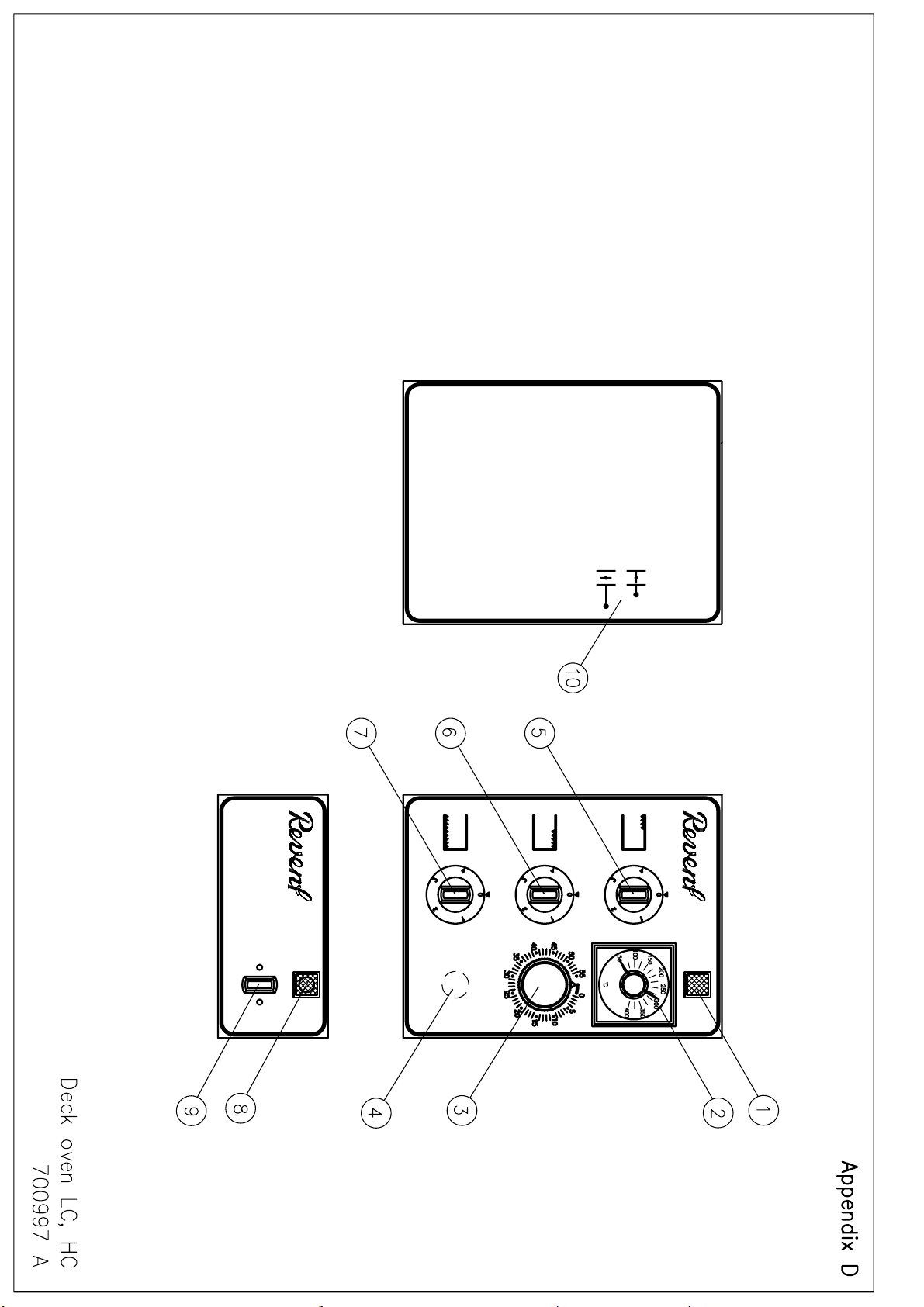
All item numbers below refer to appendix D, control panel and control box.
Control panel
(Item 1) Red pilot lamp. The red pilot lamp is lit when elements are in operation.
(item 2) Temperature regulator (max 572ºF). The temperature regulator displays the
set oven temperature. Temperature is set by turning the knob to desired
temperature according to the scale and it is indicated by the red pointer.
Current temperature is indicated by the white pointer. The temperature can
be changed during baking. IMPORTANT! If the temperature rises above
599°C, the temperature limit control will trip. This must be reset manually.
(Item 3) Baking time. The baking time is set by turning the knob clockwise to
desired time. An alarm will sound to signal the end of the bake. The baking
time can be changed during baking.
(Item 4) Steam push button. As long as this button is pushed the steam will be
transferred to the oven chamber.
(Item 5, 6, 7) Heat regulation sw itches . Each deck has thr ee controls for bottom heat, t op
heat and oven door zone heat, respectively, offering you the ability to use
individual settings for different products. Each control has setting s marked 0,
1, 2, 3 and 4 (0 (0% power) – 4 (100% power)).
(Item 8) Green pilot lamp means power on.
(Item 9) Control switch. Oven is in stop position when switch points upwards.
WARNING
CAUTION
Page 14

14
Be cautious!
and by becoming hot these items may also be a safety hazard.
Modular Deck Oven Operation Manual, October 2011
CAUTION
When opening the oven door one may get exposed to hot air and steam . The oven door
glass, inside of door, oven inter ior panels, racks, trays/pans and baked products coul d be
very hot. Prevent people and animal s from burning themselves on hot oven surfaces.
Remember, that items placed or stored close to a hot oven may be damaged and heated up
THE FIRST START-UP - BREAK IN
All position (item) numbers below refer to Appendix D.
- To minimize odour remove all visible excess grease and plastic.
- Open the dampers (item 10) on all decks.
- Turn all switches and thermostats (item 2, 3, 5, 6, 7 and 9) to "zero" position.
Switch on the main power supply (item 9) to the oven.
Break-in Step 1 (Includes both standard modular deck ovens and those with optional
stone sole)
- Set the thermostat to 150°C (item 2) on al l decks. Turn the bottom heat swi tch ( item
7), the upper heat switch ( item 6) and the door zone heat sw itch (item 5) to position
"4". The green pilot lamp (item 8) w ill turn on. Leav e the heat on for approximately
2 hours. The green pilot lamp (item 8) will go off when desired temperature is
reached.
Break-in Step 2 (Standard model only)
- Set the thermostat (item 2) at 482°F. Leave the oven heat on for tw o more hours .
Break-in Step 2 (Ovens equipped with optional stone sole only)
- Set the thermostat (item 2) at 392°F. Leave the oven heat on for two more hours.
Break-in Step 3 (Ovens equipped with optional stone sole only)
- Set the thermostat (item 2) at 527°F. Leav e the oven heat on for three more hours.
Final Step (applicable to all ovens)
- Let the oven cool off. Clean the oven chamber w ith a soft brush and clean the ov en
door window.
The oven is now ready to be used.
Page 15

Modular Deck Oven Operation Manual, October 2011
15
BAKING
Before first bake the oven must be broken-in as per instruction “ The First Start-Up - Break
In”.
- Select the baking temperature by turning the thermostat knob clockwise to the
desired temperature. Turn all heat controls (item 5, 6 and 7) to position 4. Wait
until the oven has reached set temperature (30-45 minutes), and the red pilot
lamp (item 1) goes out.
- Select appropriate settings for the heat controls (item 5, 6 and 7) on each deck
depending on type of bread being baked.
- Open the door and load the products. Close the door and give steam (item 4),
immediately, if needed.
- Select baking time with the timer (item 2).
- After the baking time has completed the buzzer will sound. Turn off the alarm by
turning the baking timer knob (item 3) counter clockwise as far as possible. Open
the door and remove the products.
BAKING WITH STEAM
Steam must be added to the oven chamber at the beginning of the baking process for
some kinds of bread. The steam has three important functions to serve:
- To make the surface of the dough smooth and pliable in order to avoid cracking.
- To increase the heat transmission to the unbaked bread at the beginning of the
baking process.
- To give the crust of the bread the right surface structure.
Steam must be added directly after the ov en door has been closed, so that the steam can
condense on the surface of the unbaked bread before it starts drying and heating up.
COOL DOWN
For cooling dow n the oven decks it is r ecommend that the heat controls are turned off and
that the damper is completely opened.
If you cool down the oven by opening the doors there is a slight risk that the doors may
warp. However, they will return to normal condition 5 to 10 minutes after being closed
again.
- Energy demanding products The heat capacity, steam capacity and their recovery (in Revent ovens) are designed to
enable baking of the most energy demanding bread products.
(Some of our oven models can be equipped with heating sections capable of supplying
more energy). Please, contact your authorized Revent dealer for more information.)
Page 16

Modular Deck Oven Operation Manual, October 2011
16
It is absolutely prohibit ed to cool down the oven by using water. This may damage the oven
chamber, oven door window and also cause personal injury.
Remember not to leave a warm oven with the door open unattended (or without warning
signs) People or animals m ight get hurt.
OVERHEATING
When the overheat protection device trips out for electric heated ovens, the heat
contactor will be shut off. To reset the high limit control the oven must first be cooled
down approx. 140°F, when the oven has cooled down the high limit switch has to be
reset.
CAUTION
CAUTION
Page 17

Modular Deck Oven Operation Manual, October 2011
17
Revent recommends the use of a REVENT AUTHORISED DEALER for all serv ice and
When cleaning the oven do not spray water, especially not with a high pressure wat er gun,
e or outside the oven. Using water on hot oven surfaces may damage the oven chamber ,
ROUTINE MAINTENANCE & SERVICE
WARNING
maintenance work.
CAUTION
insid
oven door window and also cause personal inj ury.
Chapter 4
CLEANING
- Cleaning of oven The glass of the oven door is to be cleaned with hot water and liquid detergent (not on
hot oven). The oven floor must be swept regularly and burnt grimy should be raked
away. Any non-chlorine detergent can be used for cleaning of stainless surfaces. Soda,
borax and sodium perborate are good detergents. The detergent should always be
wiped away using a wet cloth.
Greasy spots on the outside surfaces can be removed with Vienna lime. The Vienna
lime is applied with a cloth and the surface is polished in the grinding direction of the
stainless steel surface. Steel wool should never be used as it will scratch the surface.
Furthermore, non-stainless steel wool can cause corrosion on the surface. For internal
cleaning, non-metallic sponges, type Scotch Brite, can be used. The instrument panel is
cleaned with a moist cloth and liquid detergent.
MECHANICAL MAINTENANCE
- Heat unit, electric heated ovens The electric heat unit normally does not require any service. However, check the fuses
regularly. Blown fuses cause longer heating time and the oven cannot hold the right
temperature. Once a year an electrician should check the function and contact surfaces
of the contactor(s).
Page 18

Modular Deck Oven Operation Manual, October 2011
18
A worn out or damaged contactor can cause seri ous dam age to the oven and lead to related
problems.
It is very important that you follow the instruct ions for service of the burner given i n the burner
instruction handbook in the document compartment within the heat section door. If the oven is
instruction handbook.
Heat exchangers must be cold when sweepi ng is performed.
WARNING
WARNING
instructions. If the oven i s equipped with a burner from Revent you will find the burner
equipped with a burner purchased locall y, please ask the local supplier for a burner
WARNING
- Steam generator -
Steam is produced by sprinkling water over a number of flat bars. If the steam capacity
decreases, there might be lime or other deposits in the sprinkler tube. The tube should
be cleaned. In areas with high lime content in the water, it may pay off to install a
softening filter to avoid production stops. (Please, ask us for information on softening
filters.)
OVEN SAFETY CHECKS
Other safety checks
At least once a year the right hand side panel should be removed to enable cleaning
around the electrical connections. Disconnect the power with the service circuit-breaker
and vacuum clean carefully around all the connections.
Revent recommends that a REVENT AUTHORISED DEALER makes a check once a
year of the following safety device/function on the ovens oven: temperature high limit
control.
Page 19

Modular Deck Oven Operation Manual, October 2011
19
Revent recommends the use of a REVENT AUTHORISED DEALER for all serv ice and
All trouble shooting and service mentioned below could be associated with personal danger
To be safe, please contact your REVENT AUTHORISED DEALER.
The main power source to the oven must be turned off prior to service.
SYMPTOM
MEASURE
If measures 1-4 do not help, call a REVENT AUTHORISED DEALER.
The oven is slow to
1. Check the heat regulation switches and increase the settings.
COMPANY. Measures 4-6 demand a REVENT AUTHORISED DEALER.
Uneven heat
oven chamber.
1. Check the heat regulation switches and increase settings.
3. Check all heaters.
Chapter 5
TROUBLESHOOTING
WARNING
maintenance work.
WARNING
and also be of lethal risk. Some of the measures below could also be illegal if not carri ed out
by authorised personnel . Improper service and repair may void warranty.
DANGER
Oven does not heat
up
1. Check that the oven main switch is on.
2. Check the main fuse.
3. Check the (service) contactor.
4. Check that the temperature is set (red pointer) higher than actual
temperature (white pointer).
5. Check the thermostat. Turn the thermostat clockwise and check that
the red pilot lamp (item 6) is on. If it is not, the connections to the
thermostat should be checked. The thermostat may need replacing. If
the red pilot lamp is activated, the heat contactor or the elements
needs to be replaced.
6. Check that the red pilot lamp is activated.
heat up.
distribution in the
2. Check that all three phases have power.
3. Check the thermostat settings and function.
4. The temperature limit control has tripped and should be reset.
5. The heat contactor is defective and should be replaced.
6. One or many electric heaters are out of order and should be replaced.
If measures 1-4 do not help, call a REVENT AUTHORISED DEALER
2. Check all fuses.
Page 20

Modular Deck Oven Operation Manual, October 2011
20
SYMPTOM
MEASURE
Measure 3 demands a REVENT AUTHORISED DEALER.
Insufficient or no
1. Check that all valves and filters are open.
Measures 2-4 demand a REVENT AUTHORISED DEALER.
Measures 1-2 demand a REVENT AUTHORISED DEALER.
No light in the oven.
1. Unscrew the glass lamp cover in the oven chamber, unscrew the light
If measure 1 does not help, call a REVENT AUTHORISED DEALER.
The oven door falls
1. The spring needs to be replaced. Unscrew the right hand panel and
If measure 1 does not help, call a REVENT AUTHORISED DEALER.
If measures 1-2 do not help, call a REVENT AUTHORISED DEALER.
steam.
Water on the oven
floor.
down.
2. The sprinkler tube is clogged and should be cleaned.
3. The solenoid valve is defective and should be cleaned or replaced.
4. The water pressure is too low (below 4.5 kg\m²) and a booster pump
has to be installed.
If measure 1 does not help, call a REVENT AUTHORISED DEALER.
1. The outlet water pipe is clogged and should be cleaned.
2. The solenoid valve is leaking and should be cleaned or replaced.
bulb and replace it (heat resistant 300°C (572°F), E14, 40W.
the spring cover and replace the spring.
Page 21

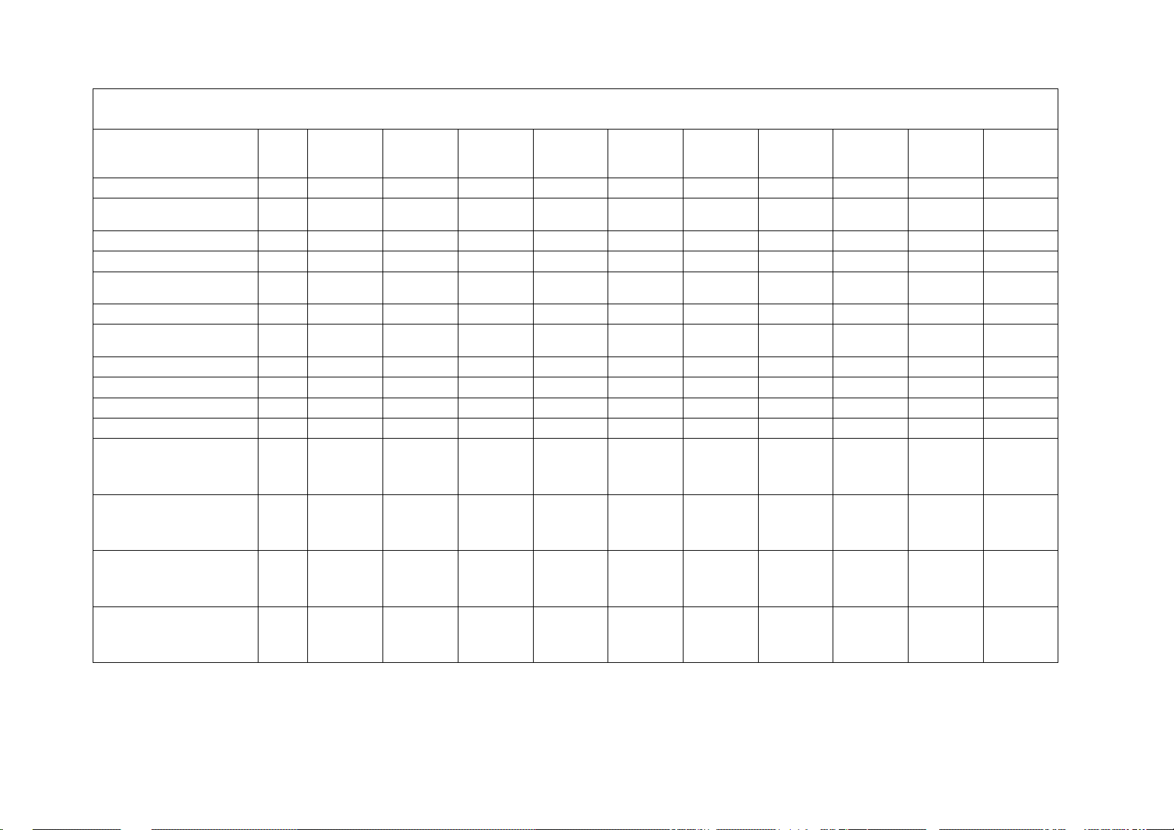
Technical specification Appendix A
Chamber interior dimensions (inch) Exterior dimensions (inch)
Module No of pans kW Width Depth Height Width Depth Height Revent part no
PAN S IZE 18" x 26"
Deck LC * 2 4.7 37.8 26.6 5.9 61.9 37.4 12.6 649302xxxx
Deck HC ** 2 4.7 37.8 26.6 7.9 61.9 37.4 14.6 649312xxxx
Top 2 62.6 37.4 4.0 6493720000
Bottom 2 62.6 37.4 4.3 6493820014
Deck LC 3 6.9 56.7 26.6 5.9 80.8 37.4 12.6 649303xxxx
Deck HC 3 6.9 56.7 26.6 7.9 80.8 37.4 14.6 649313xxxx
Top 3 81.5 37.4 4.0 6493730000
Bottom 3 81.5 37.4 4.3 6493830014
OPTIONALS
Steam generator 2 ask factory
Stone soles ask factory
Legs (set of 4), length 4" 6497010000
Legs (set of 4), length 10" 6497020000
Legs (set of 4), length 15.8" 6497030000
Legs (set of 4), length 21.7" 6497040000
Legs (set of 4), length 27.6" 6497050000
Castors (set of 4), heigth 7.5" 6498210000
Grid for oven chamber sole 29.1" x 37.8" 6498410000
Grid for oven chamber sole 29.1" x 56.7" 6498420000
UTILITY REQUIREMENTS
Standard voltage 208V / 3 / 60Hz
Water connection 5 GPH, ½" NPT connection
Page 22

Page 23

B
SPARE PARTS 3PH200-240V+PE, 3PH380-415V+N+PE, 50/60 Hz
Mechanical
Pos.
2x
18”x26”
LC
3x
18”x26”
LC
2x
600x800
LC
2x
457x762
LC
3x
457x762
LC
2x
18”x26”
HC
3x
18”x26”
HC
2x
600x800
HC
2x
457x762
HC
3x
457x762
HC
Castor
1
50239976
50239976
50239976
50239976
50239976
50239976
50239976
50239976
50239976
50239976
Door with glass
2
50239992
50239995
50239993
50239992
50239995
50239990
50239996
50239994
50239990
50239996
Glass 3 50239997
50239998
50239963
50239997
50239998
50239991
50239999
50239962
50239991
50239999
Protection batch, Glass
4
50239946
50239946
50239946
50239946
50239946
50239946
50239946
50239946
50239946
50239946
Door springs
5
50239950
50239950
50239950
50239950
50239950
50239950
50239950
50239950
50239950
50239950
Door handle
6
50239972
50239972
50239972
50239972
50239972
50239972
50239972
50239972
50239972
50239972
Door sealing, side
7
50239965
50239965
50239965
50239965
50239965
50239965
50239965
50239965
50239965
50239965
Door sealing, sole
8
50239966
50239966
50239966
50239966
50239966
50239966
50239966
50239966
50239966
50239966
Door sealing, up and low
9
50239986
50239986
50239986
50239986
50239986
50239986
50239986
50239986
50239986
50239986
Knob (door handle, damper)
10
50239973
50239973
50239973
50239973
50239973
50239973
50239973
50239973
50239973
50239973
Oven light protection glass
14
50153203
50153203
50153203
50153203
50153203
50153203
50153203
50153203
50153203
50153203
Oven light gasket
15
50287101
50287101
50287101
50287101
50287101
50287101
50287101
50287101
50287101
50287101
Stone sole
16
50239952
50239952
50239979
50239984
50239984
50239952
50239952
50239979
50239984
50239984
Page 24
B
SPARE PARTS 3PH200-240V+PE, 3PH380-415V+N+PE, 50/60 Hz
Electrical
Control box, Panel
Pos.
2x
18”x26”
LC
3x
18”x26”
LC
2x
600x800
LC
2x
457x762
LC
3x
457x762
LC
2x
18”x26”
HC
3x
18”x26”
HC
2x
600x800
HC
2x
457x762
HC
3x
457x762
HC
Control Switch
1
50239915
50239915
50239915
50239915
50239915
50239915
50239915
50239915
50239915
50239915
Pilot lamp green
Pilot lamp green USA
2
50239906
50205301
50239906
50205301
50239906
50205301
50239906
50205301
50239906
50205301
50239906
50205301
50239906
50205301
50239906
50205301
50239906
50205301
50239906
50205301
Push button (Steam)
3
50239925
50239925
50239925
50239925
50239925
50239925
50239925
50239925
50239925
50239925
Knob (for timer)
4
50204501
50204501
50204501
50204501
50204501
50204501
50204501
50204501
50204501
50204501
Timer baking 50Hz
Timer baking 60Hz
5
50113601
50152200
50113601
50152200
50113601
50152200
50113601
50152200
50113601
50152200
50113601
50152200
50113601
50152200
50113601
50152200
50113601
50152200
50113601
50152200
Thermostat
6
50239902
50239902
50239902
50239902
50239902
50239902
50239902
50239902
50239902
50239902
Pilot lamp yellow
Pilot lamp green USA
7
50239908
50205401
50239908
50205401
50239908
50205401
50239908
50205401
50239908
50205401
50239908
50205401
50239908
50205401
50239908
50205401
50239908
50205401
50239908
50205401
Knob (for switch heat)
8
50239901
50239901
50239901
50239901
50239901
50239901
50239901
50239901
50239901
50239901
Switch heat regulation
9
50239903
50239903
50239903
50239903
50239903
50239903
50239903
50239903
50239903
50239903
Panel (lower)
10
10289602
10289602
10289602
10289602
10289602
10289602
10289602
10289602
10289602
10289602
Panel (top)
11
10289601
10289601
10289601
10289601
10289601
10289601
10289601
10289601
10289601
10289601
Element
208-220V
380V
400V
415V
12
50296201
50266203
50296205
50296207
50296201
50266203
50296205
50296207
Element
208-220V
380V
400V
415V
13
50296202
50266204
50296206
50296208
50296202
50266204
50296206
50296208
Element
208-220V
380V
400V
415V
12
50239953
50296222
50296224
50296226
50239953
50296222
50296224
50296226
Element
208-220V
380V
400V
415V
13
50239954
50296223
50296225
50296227
50239954
50296223
50296225
50296227
Page 25

B
SPARE PARTS 3PH200-240V+PE, 3PH380-415V+N+PE, 50/60 Hz
Electrical
Control box, Panel
Pos.
2x
18”x26”
LC
3x
18”x26”
LC
2x
600x800
LC
2x
457x762
LC
3x
457x762
LC
2x
18”x26”
HC
3x
18”x26”
HC
2x
600x800
HC
2x
457x762
HC
3x
457x762
HC
Element
208-220V
380V
400V
415V
12
50296215
50296217
50296219
50239961
50296215
50296217
50296219
50239961
Element
208-220V
380V
400V
415V
13
50296216
50296218
50296220
50239961
50296216
50296218
50296220
50239961
Element
208-220V
380V
400V
415V
12
50296209
50296211
50296213
50239957
50296209
50296211
50296213
50239957
Element
208-220V
380V
400V
415V
13
50296210
50296212
50296214
50239958
50296210
50296212
50296214
50239958
Element
208-220V
380V
400V
415V
12
50296228
50239955
50296230
50296232
50296228
50239955
50296230
50296232
Element
208-220V
380V
400V
415V
13
50296229
50239956
50296231
50296233
50296229
50239956
50296231
50296233
Light
Light USA
14-16
50239917
50153200
50239917
50153200
50239917
50153200
50239917
50153200
50239917
50153200
50239917
50153200
50239917
50153200
50239917
50153200
50239917
50153200
50239917
50153200
Light bulb
15
50153302
50153302
50153302
50153302
50153302
50153302
50153302
50153302
50153302
50153302
Buzzer
Buzzer USA
17
50239924
50296611
50239924
50296611
50239924
50296611
50239924
50296611
50239924
50296611
50239924
50296611
50239924
50296611
50239924
50296611
50239924
50296611
50239924
50296611
Contactor
208V
220V
380-415V
18
50294108
50239905
50239905
50294108
50239905
50239905
50294108
50239905
50239905
50294108
50239905
50239905
50294108
50239932
50239905
50294108
50239905
50239905
50294108
50239905
50239905
50294108
50239905
50239905
50294108
50239905
50239905
50294108
50239932
50293807
Page 26

B
SPARE PARTS 3PH200-240V+PE, 3PH380-415V+N+PE, 50/60 Hz
Electrical
Control box, Panel
Pos.
2x
18”x26”
LC
3x
18”x26”
LC
2x
600x800
LC
2x
457x762
LC
3x
457x762
LC
2x
18”x26”
HC
3x
18”x26”
HC
2x
600x800
HC
2x
457x762
HC
3x
457x762
HC
Terminal board
19-23
Contact dealer for detalis
Fuse
24
Fuse
25
Terminal board
27
Breaking protector
28
Shunt
29
Time relay
31
Terminal board
35-36
Fuse
37
Terminal board
38-40
Temp. limit controller
Temp. limit controller USA
2TAS
50239931
50232801
50239931
50232801
50239931
50232801
50239931
50232801
50239931
50232801
50239931
50232801
50239931
50232801
50239931
50232801
50239931
50232801
50239931
50232801
Page 27

B
SPARE PARTS 3PH200-240V+PE, 3PH380-415V+N+PE, 50/60 Hz
Mechanical, Electrical
Steam generator
Pos.
2x
18”x26”
LC
3x
18”x26”
LC
2x
600x800
LC
2x
457x762
LC
3x
457x762
LC
2x
18”x26”
HC
3x
18”x26”
HC
2x
600x800
HC
2x
457x762
HC
3x
457x762
HC
Steam generator
1
20583791
20583791
20583791
20583791
20583791
20583791
20583791
20583791
20583791
20583791
Element
2
50231701
50231701
50231701
50231701
50231701
50231701
50231701
50231701
50231701
50231701
Terminal board
3
Contact dealer for details
Terminal board
4
Terminal board
5
Thermostat
Knob
6
50232701
50232711
50232701
50232711
50232701
50232711
50232701
50232711
50232701
50232711
50232701
50232711
50232701
50232711
50232701
50232711
50232701
50232711
50232701
50232711
Temp. limit control
7
50232801
50232801
50232801
50232801
50232801
50232801
50232801
50232801
50232801
50232801
Pilot lamp green
Pilot lamp green USA
8
50239906
50205301
50239906
50205301
50239906
50205301
50239906
50205301
50239906
50205301
50239906
50205301
50239906
50205301
50239906
50205301
50239906
50205301
50239906
50205301
Switch
9
50239915
50239915
50239915
50239915
50239915
50239915
50239915
50239915
50239915
50239915
Panel
10
10289603
10289603
10289603
10289603
10289603
10289603
10289603
10289603
10289603
10289603
Solenoid valve
Solenoid valve USA
11
50149801
50149807
50149801
50149807
50149801
50149807
50149801
50149807
50149801
50149807
50149801
50149807
50149801
50149807
50149801
50149807
50149801
50149807
50149801
50149807
Steam trap
12
50123402
50123402
50123402
50123402
50123402
50123402
50123402
50123402
50123402
50123402
Pipe
13
Contact dealer for details
Drain pipe
14
Page 28

Page 29
Page 30

Page 31

Page 32

 Loading...