


DM32
Retrotec Inc.
Pressure Gauge Operation Manual
For Model DM32
rev-2014-09-09

Page 2 of 94
©Retrotec Inc. 2014
Made by Retrotec Inc.
1060 East Pole Road
Everson, WA USA 98247
For support:
Call 1(888) 330-1345 in USA
+1 (360) 738-9835 outside USA support@retrotec.com or
Fax +1(360) 647-7724

Page 3 of 94
©Retrotec Inc. 2014
Copyright © 2012-2014 Retrotec Inc.
All rights reserved.
This document contains materials protected under International and Federal Copyright Laws. This book contains
material protected under International and Federal Copyright Laws and Treaties. Any unauthorized reprint or use of
this material is prohibited. No part of this book may be reproduced or transmitted in any form or by any means,
electronic or mechanical, including photocopying, recording, or by any information storage and retrieval system
without acknowledging Retrotec Inc. as the original source.
Retrotec makes no warranties with respect to this documentation and disclaims any implied warranties of
merchantability, quality, or fitness for any particular purpose. The information in this document is subject to change
without notice. Retrotec reserves the right to revise this publication without obligation to notify any person or entity
of any such changes.
Infiltrometer, FanTestic, and DucTester are Trademarks of Retrotec Inc. Other Trademarks or brand names mentioned
herein are trademarks or registered trademarks of their respective owners.
Wireless communication is certified under Wi-Fi 802.11 with ASD Model Test Plan with Test Engine for IEEE 802.11a,
b, and g Devices (Version 1.0).
This equipment has been tested and found to comply with the limits for a Class B digital device, pursuant to part 15 of
the FCC Rules. These limits provide reasonable protection against harmful interference in a residential installation.
This equipment generates, uses and can radiate radio frequency energy, and if not installed and used in accordance
with the instructions, may cause harmful interference to radio communications. However, there is no guarantee that
interference will not occur in a particular installation. If this equipment does cause harmful interference to radio or
television reception, which can be determined by turning the equipment off and on, the user is encouraged to try to
correct the interference by one or more of the following measures:
Reorient or relocate the receiving antenna.
Increase the separation between the equipment and receiver.
Connect the equipment into an outlet on a circuit different from that to which the receiver is connected.
Consult the dealer or an experienced radio/TV technician for help.
Caution: To satisfy FCC RF Exposure requirements for mobile and base station transmission devices, a separation
distance of 20 cm or more should be maintained between the antenna of this device and persons during operation.
To ensure compliance, operation at closer than this distance is not recommended.
The antenna(s) used for this transmitter must not be co-located or operating in conjunction with any other antenna or
transmitter.
This device complies with Industry Canada license-exempt RSS standard(s). Operation is subject to the following two
conditions: (1) this device may not cause interference, and (2) this device must accept any interference, including
interference that may cause undesired operation of the device.
Le présent appareil est conforme aux CNR d'Industrie Canada applicables aux appareils radio exempts de licence.
L'exploitation est autorisée aux deux conditions suivantes: (1) l'appareil ne doit pas produire de brouillage, et (2)
l'utilisateur de l'appareil doit accepter tout brouillage radioélectrique subi, même si le brouillage est susceptible d'en
compromettre le fonctionnement.

Page 4 of 94
©Retrotec Inc. 2014
Table of Contents
Important equipment-related safeguards ..................................................................................................... 8
1. Introducing the Retrotec DM32 series of digital gauge .................................... 9
2. Gauge overview ............................................................................................ 10
2.1 Make connections to the gauge ..................................................................................................... 10
2.2 Charge the battery in the gauge ..................................................................................................... 11
2.3 Power the gauge on and off – press for 2 seconds ........................................................................ 12
2.4 Read Results and control the gauge from the Home screen.......................................................... 12
2.5 Observe icons on Top Bar to monitor gauge status ....................................................................... 14
2.5.1. What speed is being sent to the fan on the “Fan Speed” output? ........................................ 14
2.5.2. Over what time period is the Result being averaged? .......................................................... 14
2.5.3. Result display can be frozen to write down values ............................................................... 14
2.5.4. Is the gauge connected to a Network? .................................................................................. 14
2.5.5. How much battery life is left in the gauge? ........................................................................... 14
2.6 Use keys on the Home screen to control gauge operation ............................................................ 16
2.6.1. [Channel A] Pressure Reading ................................................................................................ 16
2.6.2. [Channel B] Pressure Reading or Result ................................................................................ 16
2.6.3. Set the [Range/Device] connected to the gauge ................................................................... 17
2.6.4. Estimate Results with [@ Pressure] ....................................................................................... 19
2.6.5. Setting “n value” for @Pressure extrapolation ..................................................................... 20
2.6.6. Capture and apply a Baseline using [Settings] ....................................................................... 20
2.7 Gauge compensates for sensor drift with Auto Zero ..................................................................... 20
3. Get Results directly from the gauge ............................................................... 21
3.1 Connect Speed Control Cable between the gauge and fan ............................................................ 21
3.2 Connect pressure tubes to gauge ................................................................................................... 21
3.3 Control the test and read Results on the Home screen ................................................................. 21
3.3.1. Tap [Range/Device] to match Range on Device in use .......................................................... 21
3.3.2. Tap [Range/Device] [Change Device] to change Device in use ......................................... 21
3.3.3. Tap [Set Speed] to run the fan at a particular speed ............................................................. 22
3.3.4. Tap [Jog] keys to adjust speed up or down 5% ...................................................................... 22
3.3.5. Tap [Set Pressure] to achieve a particular enclosure pressure ............................................. 23
3.3.6. Tap [Jog] keys to adjust pressure up or down 5 Pa ............................................................... 24
3.3.7. Tap [Area] or [Volume] to enter dimension for particular Results ........................................ 24
3.3.8. Tap [Channel A] to “Hold” readings and results .................................................................... 25

Page 5 of 94
©Retrotec Inc. 2014
3.3.9. Tap [Channel B] or [Settings] to change Result or units to be displayed .............................. 26
3.3.10. Tap [@ Pressure] to estimate Result at a different pressure ................................................ 27
4. Change [Settings] for gauge operating parameters ........................................ 32
4.1 Capture [Baseline] Pressure ........................................................................................................... 32
4.2 Set [Area] if using a Result per Area ............................................................................................... 33
4.3 Set [Volume] if using ACH ............................................................................................................... 34
4.4 Use metric units for dimensions ..................................................................................................... 35
4.5 Set the [Default @ Pressure] .......................................................................................................... 36
4.6 Set [Time averaging] period ........................................................................................................... 38
4.7 Change Result and units to be displayed........................................................................................ 39
4.8 Set up “Network” if using Ethernet connection ............................................................................. 41
4.9 View and update the [Firmware] version, check serial number .................................................... 42
4.10 Re-calibrate the touchscreen ......................................................................................................... 43
4.11 Reset button ................................................................................................................................... 44
5. Remotely run tests and save results with Retrotec software ......................... 45
5.1 Connecting gauges to a computer .................................................................................................. 45
5.2 Connect single gauge to a computer with Ethernet cable ............................................................. 45
5.3 Connect multiple gauges to a computer via “Wired” network ...................................................... 47
5.4 Connect computer or phone to the DM32 “WiFi” Hotspot ........................................................... 49
5.5 Make the DM32 join an existing “WiFi” network ........................................................................... 51
5.5.1. Set secure wireless credentials using DM32 Configurator software ..................................... 52
5.5.2. On DM32, verify wireless credentials after updating ............................................................ 52
6. Update gauge with new features ................................................................... 54
6.1 Connect the gauge to a computer via USB ........................................................................ 54
7. Verify your gauge accuracy between factory calibrations .............................. 56
8. What to do if you have trouble with the gauge ............................................. 59
8.1 Re-calibrate touchscreen if keys don’t respond well to taps ......................................................... 59
8.2 Gauge may get stuck running “Re-calibrate touchscreen” if the battery gets into a low state ..... 60
8.3 Reset if you need to clear the gauge to base settings .................................................................... 60
8.4 Flashing screen may appear as gauge recovers from deep discharge ........................................... 60
8.5 Pressing power button may not turn gauge On if battery is fully discharged................................ 60
8.6 Gauge will not reset (run splash screen) while gauge is plugged into power ................................ 60
8.7 Flashing yellow LED on front means gauge had an internal malfunction ...................................... 60

Page 6 of 94
©Retrotec Inc. 2014
8.8 Calculated Result will be wrong if the Range and Device installed on fan are different than those
selected on the gauge ................................................................................................................................. 61
8.9 Moving tubes might cause fluctuating pressure readings ............................................................. 61
8.10 Fans with a single tube have results adjusted by gauge ................................................................ 62
8.11 Pressure can overshoot when using the Set Pressure key ............................................................. 62
8.12 Check if large fixed errors are caused by pinched tubes ................................................................ 63
8.13 Check if large fixed errors are caused by water in the tube ........................................................... 64
8.14 Check if large fixed errors are caused by sun heating the tubes.................................................... 65
8.15 Check if wind is causing fluctuating pressure ................................................................................. 65
8.15.1. Use the [@ Pressure] key to reduce the effects of wind ....................................................... 65
8.15.2. Use Time Averaging feature to reduce the effects of wind ................................................... 65
8.15.3. Let Time Averaging take effect before making readings ....................................................... 65
8.15.4. Use Baseline feature to reduce the effects of a constant wind ............................................ 66
8.15.5. In extreme cases you can use a Wind Damping Kit designed to reduce wind-related
fluctuations ............................................................................................................................................. 66
9. Technical Specifications ................................................................................. 68
Appendix A: Understanding Pressures on the Gauge ........................................... 70
Differential Pressure .................................................................................................................................... 70
Positive vs. Negative Pressure ..................................................................................................................... 70
Why static and fluctuating pressures occur, causing bias ........................................................................... 71
Managing fluctuating pressures created by wind ....................................................................................... 72
Reduce uncertainty in results by taking lots of readings ............................................................................ 72
Appendix B: Flow Equations used with Devices ................................................... 74
Appendix C: Manually estimate Flow if required test pressure cannot be reached
............................................................................................................................ 79
Cannot Reach 50 Pa Factors ........................................................................................................................ 80
Cannot Reach 25 Pa Factors ........................................................................................................................ 81
Appendix D: Details about the @Pressure extrapolation function ....................... 82
“n value” for @Pressure extrapolation ....................................................................................................... 83
Errors occur in estimated flow if gauge and actual “n” don’t match .......................................................... 84
Appendix E: Tables to adjust Flow values for temperature difference ................. 87
Appendix F: Tables to correct Flow if range selected did not match the installed
range ................................................................................................................... 89
Appendix G: Measure Supply or Exhaust flow with a gauge and box .................. 90

Page 7 of 94
©Retrotec Inc. 2014
Glossary ............................................................................................................... 92

Page 8 of 94
©Retrotec Inc. 2014
Important equipment-related safeguards
Read and save these instructions
When using electrical appliances, basic safety precautions should always be followed. If Retrotec equipment is
used in a manner that does not follow the information provided in this manual, safety to the operator and
equipment performance may be impaired.
The risk of fire, electric shock, and injury to persons may result during cleaning of the gauge. To avoid these risks,
unplug or disconnect the gauge from the electrical power supply and turn the gauge off before cleaning. Clean
only by wiping with a soft dry cloth. There are no user serviceable parts on the gauge.
To protect against the risk of fire, electric shock, and injury to persons during gauge operation:
Do not operate any gauge with a damaged electrical cord. Discard gauge or return to an authorized service
facility for examination and/or repair.
Do not run cord under carpeting. Do not cover cord with throw rugs, runners, or similar coverings. Do not route
cord under furniture or appliances. Arrange cord away from traffic and where it will not be tripped over.
Do not place this equipment or power cord in water or other liquid.
Use only the included power plug to charge and/or operate the gauge.
Turn the unit off and unplug the charger (if in use) from electrical outlet before moving.
For use under indoor conditions only, where there is no exposure to water or dusty substances or explosive
materials or flammable materials.
Do not use equipment for other than its intended use.
Equipment is intended for diagnostic testing andmust be operated by a qualified operator.
Failure to follow these instructions carefully may result in bodily injury, damage to property and/or equipment
failure. Failing to operate equipment as intended may void warranty and compliance with CE mark and other
listings.
Page 9 of 94
©Retrotec Inc. 2014
1. Introducing the Retrotec DM32 series of digital gauge
The DM32 is the next generation digital manometer, with touchscreen and two digital pressure sensors. It
is a small, lightweight dual- channel pressure gauge with computer control options via USB or over a
network via Ethernet.
The DM32 series utilizes the latest in microcontroller technology allowing the unit to support a rich set of
capabilities including full color touchscreen display, pre-calibrated digital pressure sensors, high capacity
rechargeable Lithium Polymer battery, onboard charging and power management, USB connectivity, and
wired and optional wireless (WiFi) networking capabilities.
The DM32 includes a suite of software to maximize your use of the gauge. The DM32 Software Suite (for
PC) includes a Data Logger, Virtual Gauge for remote control, and the DM32 Configurator. DM32 gauge
internal software can be updated with new features as they get developed from time to time, using the
DM32 Configurator software and the USB connection on the DM32. WiFi enabled gauges also include the
GaugeRemote App for Android and iOS based smart phones and devices.
The gauge will conveniently control the speed of fans that create flow such as Blower Door Fans,
DucTesters and other flow devices. It will also calculate the flow rate going through these devices as well as
many passive devices such as flow grids. Results can be displayed in any series of units used anywhere
worldwide.
Words in square brackets indicate keys that must be tapped on the touchscreen to operate the gauge. The
ON- OFF key must be pressed and held for two seconds in order to actuate while all other Touch-Screen
functions are Tap and Release to actuate.
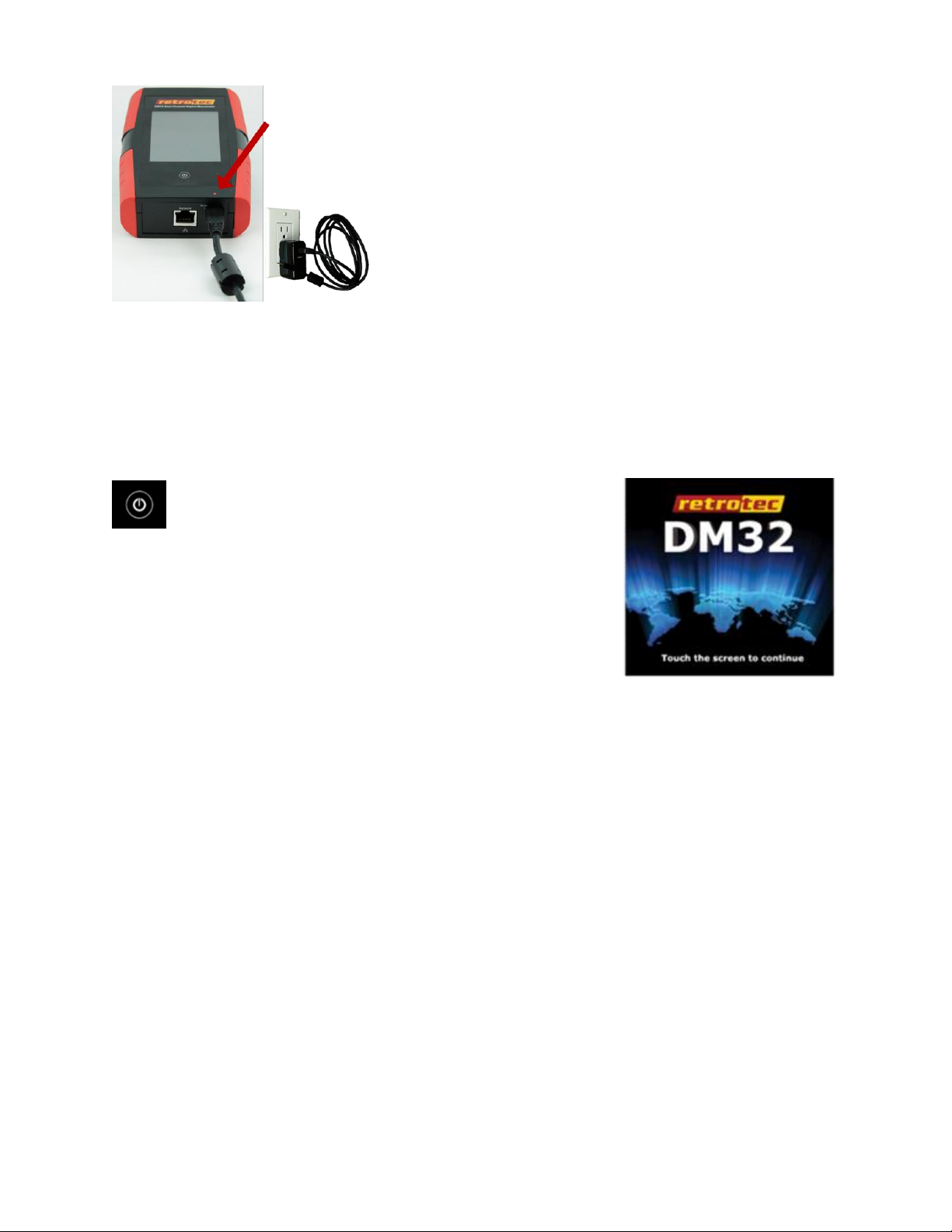
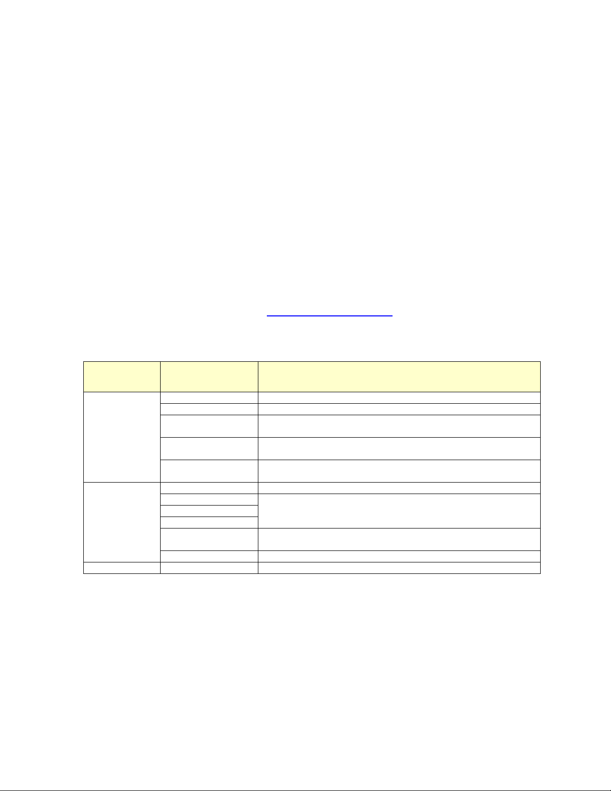
Figure 1: DM32 digital gauge has been turned on and is ready for action.
Page 10 of 94
©Retrotec Inc. 2014
2. Gauge overview
The front of the gauge has a resistive touchscreen, a touch-sensitive [Home] button , and a battery
charge indicator light. Because the screen is resistive, it can be operated when the user is wearing gloves,
and in most environmental conditions.
The top of the gauge has four color-coded pressure tube ports, and a Control output port (for fan speed)
The bottom of the gauge has an Ethernet network port (for gauge-computer communications), a USB port
(mainly for battery charging), and a Reset button (recessed, accessible using a paper clip).
The touchscreen serves as both the information display and the keypad for the gauge. The information
displayed depends on selections a user makes by tapping on the touch sensitive areas on the screen, called
“keys” in this manual and shown in square brackets [].
2.1 Make connections to the gauge
Physical connections from the gauge to a calibrated fan are on top of the gauge. Physical connections to a
computer or power adapter are on the bottom of the gauge.
An Ethernet-style cable from the fan speed output control port connects to a calibrated fan to control its
speed. The cable supplied for this purpose with Retrotec systems is yellow.
Pressure tube ports on the top of the gauge are color-coded to distinguish where pressure tubes are
connected. Retrotec has a specially designed pressure tube port that grips pressure tubes well, but
releases them without tearing after long-term use. This exclusive connector is designed by Retrotec to
make contact with the both tube internally and externally with a shallow taper.
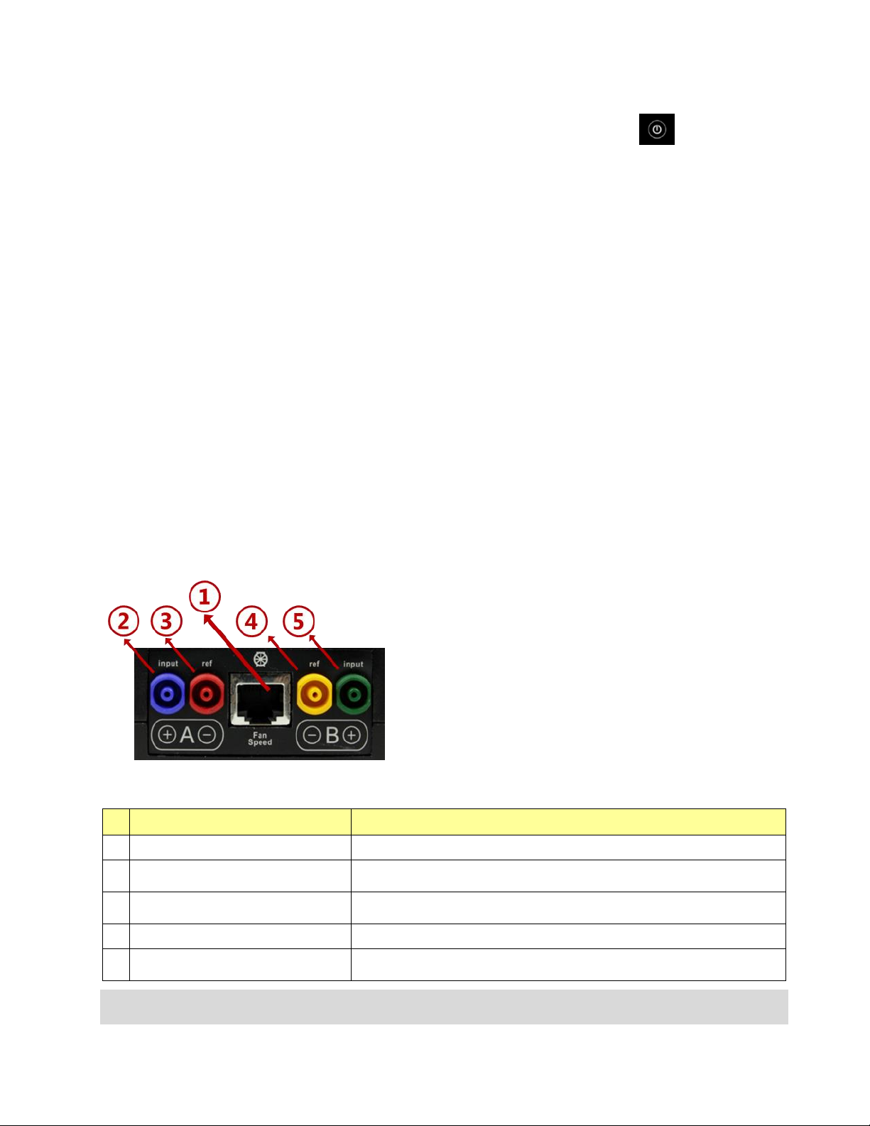
Figure 2: Connect tubes and Speed Control Cable
Table 1: Physical connections from gauge to fan are on top of gauge
gauge port
connection
1
“Fan Speed” control cable port
Connect the yellow Retrotec-proprietary Speed Control Cable
2
Blue pressure port: “input B (+)”
Often has no pressure tube connected. For duct testing, a blue pressure tube
leads from the gauge into the ducts.
3
Red pressure port: “ref B (-)”
Connect the red pressure tube from the gauge through the Door Panel to the
outdoors.
4
Yellow pressure port: “ref A (-)”
Connect the yellow pressure tube from gauge to yellow port on a Retrotec fan
5
Green pressure port: “input A (+)”
Connect green pressure tube to green port on Retrotec fan, if applicable. No
pressure tube will be here if Retrotec fan does not have a green pressure port
Pressure tubes should be clean and not stretched in order to make a proper connection. If a pressure tube is
damaged, simply slice a short piece of tube off the end to ensure a clean fit. Tubing can crack in cold weather, but can
Page 11 of 94
©Retrotec Inc. 2014
be heated in hot water before being handled. Be careful to dry all water from the tubing prior to connecting since
water in the tube is a major source of measurement error.
Connections on the bottom of the gauge provide a USB charging input and remote control port as well as
an Ethernet remote control port. An Ethernet cable of type Cat5e or Cat6 from the “Network” port can
connect the gauge directly to a PC, to an Ethernet switch, or to a router. Ethernet cables have a maximum
length of 328 ft (100 m); over longer lengths signal strength may be compromised.
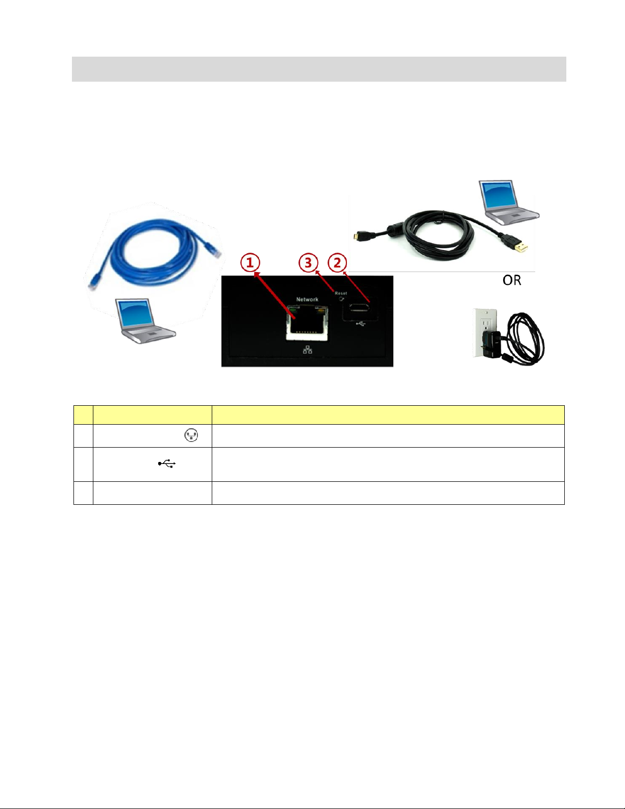
Figure 3: Connect charger or remote computer control
Table 2: Physical connections from gauge to a computer or charger are on the bottom of gauge
gauge port
connection
1
“Network” cable port
A Cat5e or Cat6 Ethernet cable can connect the gauge to a computer, a switch, or a router,
in order to control fan and/or read the gauge measurements via the computer
2
USB cable port
Connect the USB “A”/“Micro-B” cable to a PC or the supplied AC power adapter in order to
charge the internal battery of the gauge.
Connect the USB to a computer to update the software internal to the gauge (firmware).
3
“Reset”
Press a paper clip into the hole to reset the gauge – forces the gauge to turn off and back
on again.
2.2 Charge the battery in the gauge
The gauge is charged at the factory, but you can plug it in to ensure a full charge before each test. Connect
the USB cable to the AC power adapter to charge the gauge battery. Charging using the AC power adapter
is the only way to fully charge the gauge. Plugging the gauge into a computer USB port will extend the
length of the charge but the gauge will eventually need to be recharged using the AC power adapter.
With the AC adapter, a full charge will be completed in about four hours. A fully charged gauge will last for
approximately 8 hours without a recharge. For details see 2.5.5
Page 12 of 94
©Retrotec Inc. 2014
Figure 4: Red light shows that gauge battery is charging
When connected to the computer USB port, the gauge still discharges very slowly. Connection to the
computer USB is just a way to extend the time available on a charge, so that you can run longer tests if you
have a computer nearby.
2.3 Power the gauge on and off – press for 2 seconds
Warning: Gauge does not turn on immediately. You don’t need
to press the screen overly hard. You may break the glass.
Figure 5: Gauge [Home] key and power on/off key
Press the power on/off key and remove your finger. After two
seconds, you will hear a click as the gauge starts up, then the Splash
Screen will be displayed. Press on/off for 2 seconds to power off.
The Splash Screen is visible until the user taps anywhere on the screen
or until the gauge self-check sequence finishes and automatically
displays the Home screen.
Information displayed on the Splash Screen during start up includes:
Internal gauge software (Firmware) Build and Version Number
Gauge Serial Number
Upon gauge start up, the Home screen will display the Device, Range, and Result to be displayed settings
that were set on the gauge before it was last powered off, so the user can immediately start testing if they
are using the same equipment.
2.4 Read Results and control the gauge from the Home screen
The Home screen is the main display that allows a user to control the gauge. The gauge includes
convenience functions to support operation of pressure measurement systems with calibrated fans, and
calculate results for air leakage testing.
In this manual, words that are in square brackets indicate keys that can be tapped to change something on
the gauge.
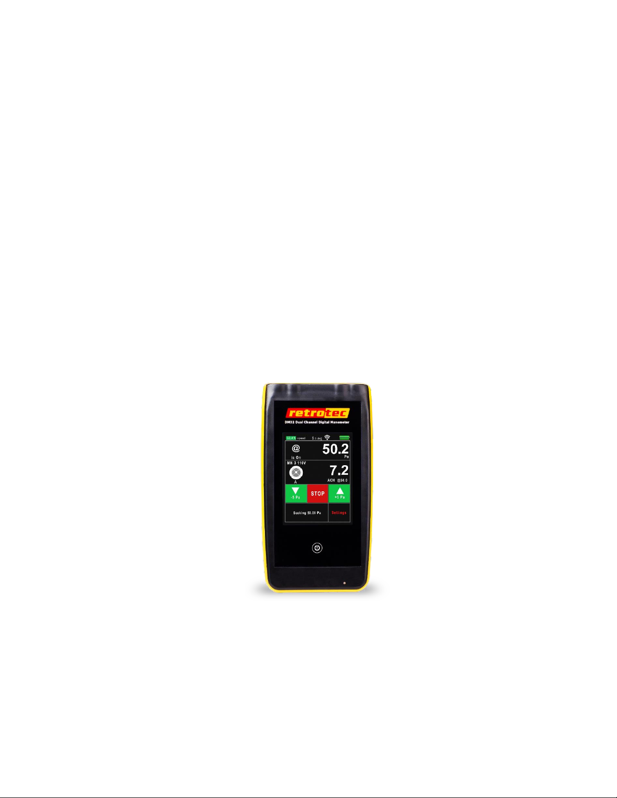
Figure 6: DM32 splash screen shows
while gauge starts up
Page 13 of 94
©Retrotec Inc. 2014
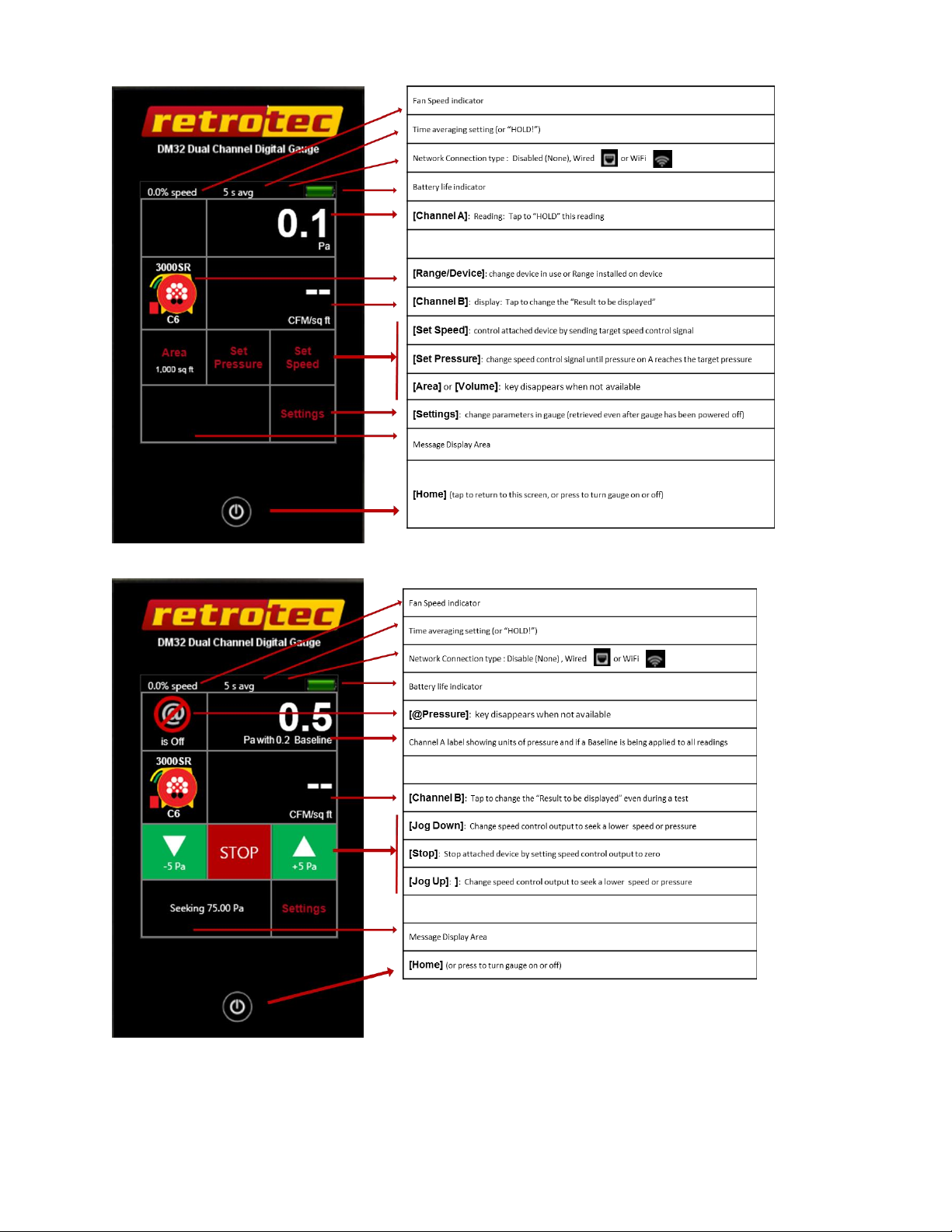
Figure 7: Home screen keys when the gauge is idle (not controlling a fan)
Figure 8: Home screen keys when gauge is seeking a target pressure
Page 14 of 94
©Retrotec Inc. 2014
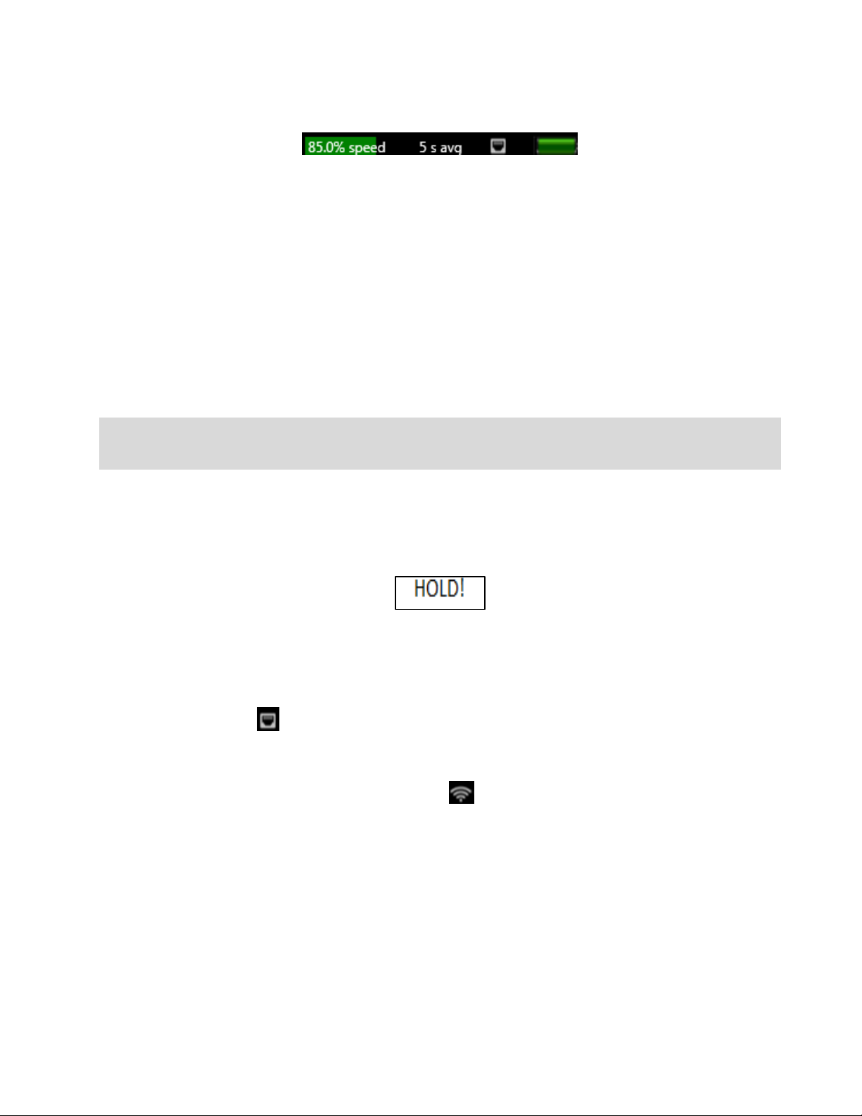
2.5 Observe icons on Top Bar to monitor gauge status
Icons on the Top Bar indicate the current status and various settings on the gauge.
Figure 9: Top Bar
2.5.1. What speed is being sent to the fan on the “Fan Speed” output?
The % Speed indicates the percentage of the fan’s total speed capacity that the gauge is directing the fan to
achieve (85% Fan Speed shown in the example above).
2.5.2. Over what time period is the Result being averaged?
When Time Averaging is active, the gauge will display the time that the [Channel A] and [Channel B]
Readings are averaged over. 5 second Time Averaging is shown in Figure 9. Regardless of the time
averaging setting, the display will update every second.
Time Averaging periods of 1s, 5s, 10s, 30s can be selected directly, or another time to spend averaging can
be entered manually.
Tip: When changing the fan speed, set pressure, or taking a reading after making any other changes, wait for twice
the Time Averaging period to elapse before taking a reading. Taking a reading too quickly can lead to recording
incorrect results.
2.5.3. Result display can be frozen to write down values
When the [Channel A] Reading is tapped, “HOLD!” will instead be displayed (and flashes) in place of the
Time Averaging value to indicate [Channel A] and [Channel B] display values are frozen to the values that
were present when the display was tapped.
Figure 10: Tapping [Channel A] display area will "HOLD" the Result
2.5.4. Is the gauge connected to a Network?
The wired network icon appears when the network Status is set to “Wired”. ([Settings] [Network]
[Status]) Set ”Wired” when an Ethernet cable is connected to the “Network” cable port on the bottom
of the gauge.
For a DM32 with WiFi capability enabled, the WiFi icon appears when the network Status is set to one
of the WiFi choices and the gauge successfully connects to the associated wireless network. Set ”WiFi-
Create” to have the gauge generate a WiFi hotspot to which a phone or computer can connect, or set
”WiFi-Join” to have the gauge connect to an existing WiFi network. See section 5.4 for full instructions on
connecting your DM32 to a “WiFi” network.
Gauges with serial numbers starting with 4 have WiFi capability which can be enabled if the WiFi module is
purchased.
2.5.5. How much battery life is left in the gauge?
Page 15 of 94
©Retrotec Inc. 2014
The battery life indicator shows how much life is left in the rechargeable battery inside the gauge. A fully
charged battery will last approximately 8 hours before needing recharging. Gauges will discharge faster if
WiFi is being used. To extend battery life, choose a “Network” setting of “Disabled”
The gauge battery is charged via the USB cable port on the gauge. The fastest way to charge the gauge is to
plug the USB cable into the provided USB-to-mains AC power adapter, as the mains adapter will provide
maximum current. Plugging the USB cable into a USB port on your computer will also charge the gauge,
but at a much slower rate, and will only extend the length of time before needing to use the AC adapter
(the draw can be higher than what most computers normally provide on the USB output).
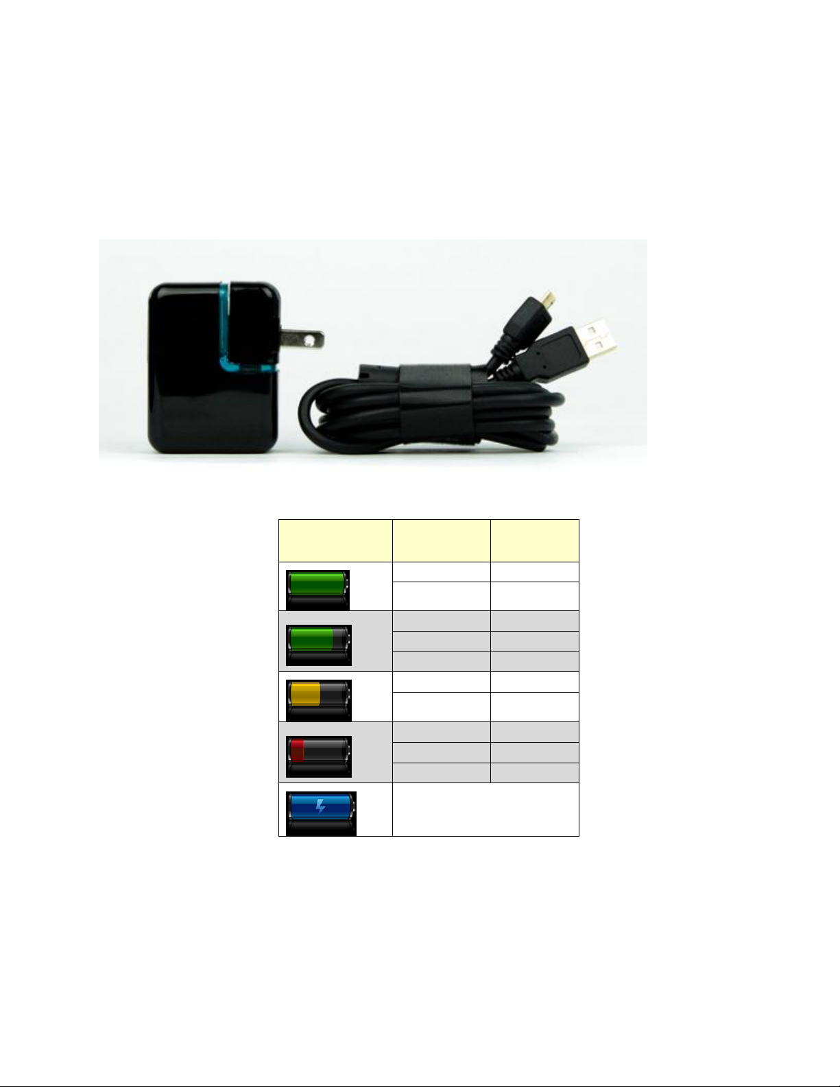
Figure 11: AC Adapter provided to charge battery via USB connector
Table 3: Gauge battery life indications
Battery life
indicator icon
Battery life
remaining
Electrical
Potential
100 %
≥4.2 V
90 %
4.12 V
80 %
4.04 V
70 %
3.96 V
60 %
3.88 V
50 %
3.80 V
40 %
3.72 V
30 %
3.64 V
20 %
3.56 V
10 %
3.48 V
DM32 is Charging (USB from
DM32 is connected to power)
When the battery is charging, a red light on the front of the gauge (bottom right corner) will be on solidly
(not flashing). Once the light goes off, the gauge is fully charged. Additionally, the battery life indicator on
the Top Bar will be blue when the battery is being charged and the gauge is powered on.
With the gauge plugged into the wall outlet, the battery charges at 1A, and will take approximately 4.2
hours to fully charge a depleted battery. With the gauge plugged into the USB port of a computer, it
charges at around 500mA, not enough to maintain the gauge so will not charge the battery.

Page 16 of 94
©Retrotec Inc. 2014
When the gauge is plugged into mains power on a completely depleted battery, it may take a few minutes
to gain sufficient charge to have enough power to show the splash screen. If you press the power button
and the screen flashes without showing the splash screen, this indicates the gauge is still in the process of
gaining enough charge and will start shortly. (the gauge may also repeatedly run the Re-calibrate
touchscreen procedure when battery is too low). Plugging the gauge into the computer when the battery is
depleted will not provide enough power to restore the gauge, it must be plugged into mains power.
The Lithium-Polymer rechargeable battery provided with the gauge can last up to 3 years. Once the battery
becomes unable to hold a charge, it must be changed. Changing the battery will require return to the
factory, conveniently at about the same time that the gauge will need a factory re-calibration.
2.6 Use keys on the Home screen to control gauge operation
2.6.1. [Channel A] Pressure Reading
The [Channel A] display always shows the pressure difference between the blue pressure port “input A”
and the red pressure port “ref A”. If the pressure tubes are connected as illustrated in Retrotec’s Door Fan
Operation manual, [Channel A] shows the building pressure.
The pressure units can be displayed in units of Pa, psf or in WC. To change the units for the [Channel A]
Reading, from the Home screen, tap [Settings] [Result to be displayed] [Pressure:] until the desired
units are displayed.
The [Channel A] Reading will be negative if there is a higher pressure on the “-“ (red) pressure port
The [Channel A] Reading will be positive if there is a higher pressure on the “+“ (blue) pressure
port
The [Channel A] Reading is also a key; when it is tapped the [Channel A] and [Channel B] displays are
frozen. This feature is convenient for jotting down test data. “HOLD!” will be displayed in the Top Bar to
indicate the readings have been frozen.
2.6.2. [Channel B] Pressure Reading or Result
The [Channel B] display can show the pressure difference between the yellow pressure port “ref B” and the
green pressure port “input B”. If the pressure tubes are connected as illustrated in Retrotec’s Door Fan
Operation manual, [Channel B] shows the Fan Pressure.
The [Channel B] pressure will be negative if there is a higher pressure on the “-“ (yellow) pressure
port
The [Channel B] pressure will be positive if there is a higher pressure on the “+“ (green) pressure
port
The gauge can also use the pressure on Channel B to calculate and display different results for the [Channel
B] Result, such as:
Pressure: Pa, psf or in WC
Flow: CFM, L/s, cu m/s, cu m/h
Flow/Area (Permeability): CFM/sq ft, CFM/100 sq ft, CFM/1000sq ft, (cu m/h)/sq m, (L/s)/sq m
Air changes per hour: /h
Equivalent leakage area extrapolated to 10 Pa, “EqLA10”: sq ft, sq in, sq cm
Equivalent leakage area, “EqLA”: sq ft, sq in, sq cm
Effective leakage area, “EfLA”: sq ft, sq in, sq cm
Effective leakage area extrapolated to 4 Pa, “EfLA4”: sq ft, sq in, sq cm
Page 17 of 94
©Retrotec Inc. 2014
Equivalent leakage area per enclosure area at 10 Pa, “EqLA10/area”: sq in/sq ft, sq cm/sq m)
Effective leakage area per enclosure area at 4 Pa, “EfLA4/area”: (sq in/sq ft, sq in/100sq ft, sq ft/sq
ft, sq cm/sq m)
The [Channel B] display is also a key: when tapped, the “Result to display” on [Channel B] will change. In
the list that shows up, tapping a [Result] to highlight it (in brighter red), will select it as the displayed
[Channel B] Result of choice. Once highlighted, the [Result] can be tapped repeatedly to cycle through all
the different units available for display of that Result.
Refer to Retrotec’s Residential & Commercial Airtightness Requirements document for Results required
according to various standards, codes, and regions.
2.6.3. Set the [Range/Device] connected to the gauge
“Device” refers to the calibrated fan or other device being used to conduct the current test in conjunction
with the gauge. It is important to make sure that the correct Device is selected because the calculation for
each of the Results is based on equations that are different for each Device.
“Range” or “Range Configurations” are the rings or plates installed on a calibrated fan to limit the air flow
through it, so that the fan can achieve a measurable Fan Pressure, even when moving only a small amount
of air (for more information, see Retrotec’s Manual-Door Fan Operation). Select the Range that matches
the Range Ring or Plate that is installed on the fan to ensure that the gauge performs accurate calculations
and displays correct results.
Table 4: List of devices compatible with the DM32
Device
Manufacturer
Device displayed
Description
Retrotec
200
Model 200 fan, DucTester
1000
Model 1000 systems with 0.75 hp yellow wheel rim style fans
2000
Model Q46 and Q56 systems with 0.75 hp yellow foam core fan. Same
curves as 1000.
3000
Older Model Q4E, Q5E and QMG systems with 2 hp yellow foam core
Door Fan. Same curves as 1000.
3000SR
Model Q4E, Q5E and QMG systems with 2 hp yellow foam core Door Fan –
all fans are self-referencing (have green tube)
TEC
MN DB
Duct testing fan
MN 3 (110V)
0.75 hp black wheel rim style fan
MN 3 (230V)
MN 4 (230V)
Exhaust
Exhaust Fan Flow Meter – measures air flow through residential exhaust
fans between 10 and 124 CFM.
TrueFlow®
True Flow Grid – measures flow through a residential air handler
Generic
Hole Flow
Plate with a hole of a known size
Retrotec calibrated fans connected to the gauge with a Speed Control Cable can have their speed of
operation controlled by the gauge through the “Fan Speed” control output.
Fans manufactured by TEC (such as the DuctBlaster or Minneapolis Model 3 or 4) can be controlled by the
gauge “Fan Speed” control output if an optional Retrotec-TEC Fan speed control Adapter is connected
between the gauge and the TEC fan, in line with the Speed Control cable as shown in Figure 12. The
Minneapolis fan speed control must have the cruise input.
Connecting the pressure tubing to your TEC fan as described in Retrotec literature allows the gauge to
correctly calculate results.
Page 18 of 94
©Retrotec Inc. 2014
Figure 12: Control a TEC fan using the gauge and Fan Speed Control Adapter (part FN275, produced by Retrotec)
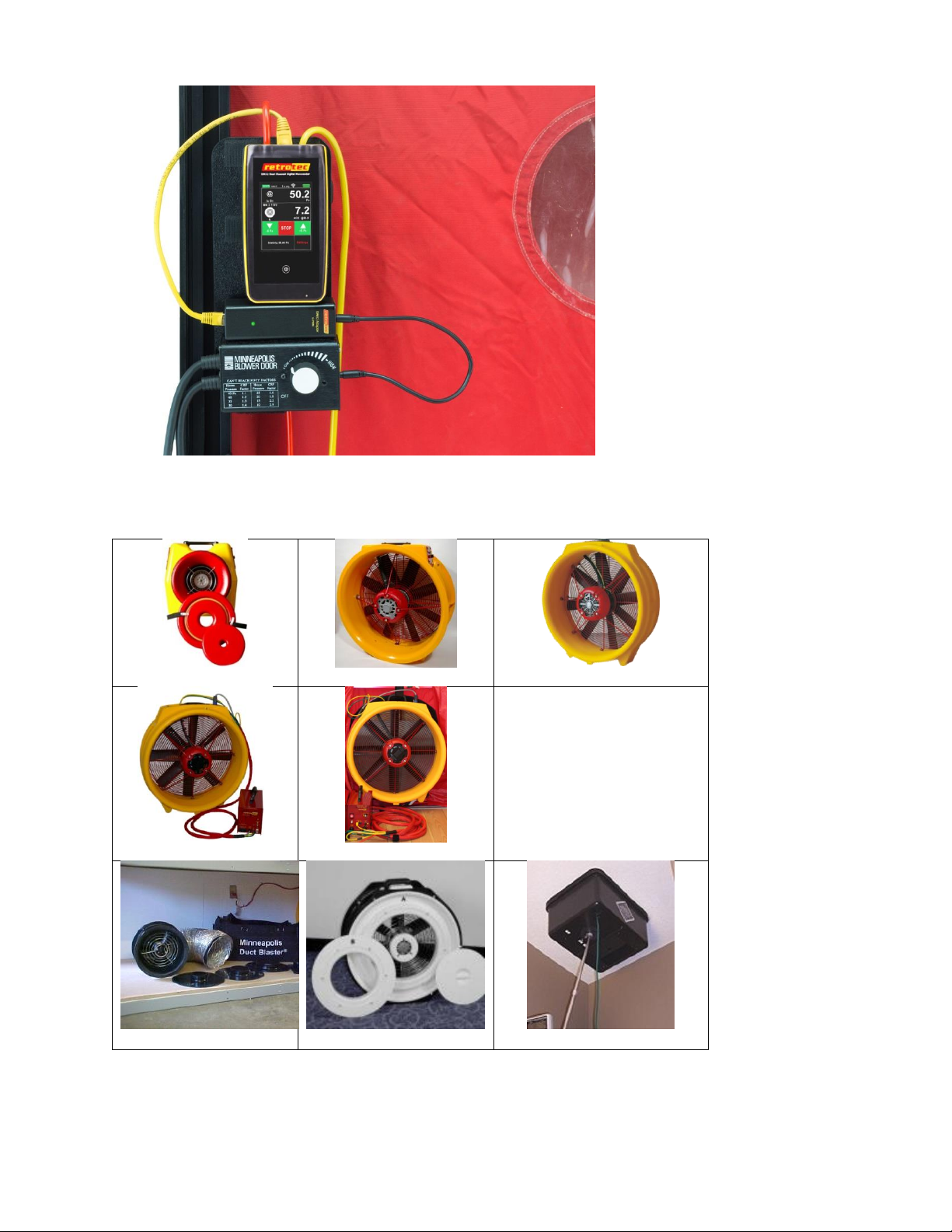
Table 5: Images of devices compatible with the gauge
“200”
“1000”- yellow tube only
“2000”- yellow tube only
“3000”- yellow tube only
“3000SR”-yellow and green tube
“MN DB”
“MN 3/4”
“Exhaust” (Fan Flow Meter)
Page 19 of 94
©Retrotec Inc. 2014
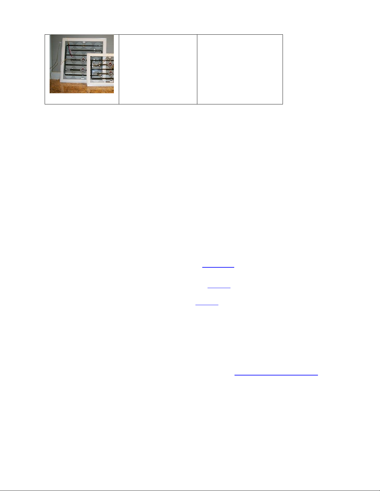
“TrueFlow”
2.6.4. Estimate Results with [@ Pressure]
The [@] pressure key enables the gauge to calculate and display the estimated [Channel B] Result that
would be achieved, as if the target pressure was reached (also known as “extrapolation”). The [@
Pressure] key only appears on the Home screen if [Set Speed] or [Set Pressure] functions are used and the
gauge is measuring pressures on Channel A and B.
This function is useful in situations when the fan has reached 100% speed and the enclosure
pressure still has not reached the target pressure.
Additionally, this function is useful since the measured [Channel A] pressure will usually be slightly
over or under the desired/set pressure, making it difficult to report results that exactly at the
specified pressure.
Tapping [@ Pressure] will toggle the extrapolation function on or off. The label under [Channel B] display
will change to indicate whether [@ Pressure] “is On” (e.g., CFM@25.0Pa) or “is Off” (e.g., CFM).
Details of how the gauge calculates the flow at exactly the target pressure, when [Channel A] has not
reached exactly the set target pressure, can be found in Appendix D.
If the [Set Speed] function is used, [@ Pressure] extrapolates the [Channel B] Result to the [Default
@ Pressure] set in the “Settings” screen, using the “n value” chosen in [Settings].
If the [Set Pressure] function is used, [@ Pressure] extrapolates the [Channel B] Result to the
pressure entered for [Set Pressure], using the “n value” chosen in [Settings].
The @ Pressure function provides unique advantages over non-extrapolated results:
There is no need to achieve an exact [Channel A] pressure (e.g. to a precision of 0.1 Pa)
[Channel B] Results can be obtained even if the test pressure cannot be reached**
**Although the gauge can extrapolate results to any pressure, it is more accurate when the actual
enclosure pressure read on [Channel A] is close to the target pressure. As a rule of thumb, extrapolation
can be used if the actual enclosure pressure reaches at least 80% of the target pressure. If 80% cannot be
reached, more fans are needed to complete the test (See Retrotec’s Manual-Lge-Multi-Fan Testing).
Example #1 - Inaccuracy
A 50 Pa building pressure is desired, but only 20 Pa can be reached (due to severe leakiness). In this
instance, the extrapolated results for flow “@ 50 Pa” do not represent the reality of the testing conditions
and might be highly inaccurate.
In the same situation, a 45 Pa building pressure is achieved. The extrapolated “@ 50 Pa” pressure is now
much more accurate, and provides an acceptable result.

Page 20 of 94
©Retrotec Inc. 2014
2.6.5. Setting “n value” for @Pressure extrapolation
The “n value” is a number set between 0.5 and 1.0 that is used in the calculation when extrapolating
[Channel B] results to a pressure that is not the pressure read on [Channel A]. It can be changed by tapping
[Settings][…] [Ducts=0.6, House=0.65]. Set it to 0.65 for houses, and 0.60 for ductwork. Set to 0.5 for
tests using the Retrotec House or duct simulator, air handler flow and any large hole that is not composed
of long thin cracks.
Technical details about the “n value” are shown in Appendix D.
2.6.6. Capture and apply a Baseline using [Settings]
Some buildings have an initial pressure imbalance between the indoors and outdoors, prior to any testing.
This pressure imbalance is called the Baseline pressure, bias pressure, or static pressure. The Baseline
function allows the user to capture the Baseline pressure under the existing test conditions. See Section
4.1 for illustrations of how to capture a Baseline. Once captured, the gauge will automatically subtract the
Baseline pressure from all subsequently measured pressure readings, and will display only the adjusted
pressures on the screen. The gauge averages Baseline pressure for a user-defined duration.
Tip: A 30 second Baseline acquisition is typically enough to establish an accurate baseline measurement. If the
building conditions change during the test, the baseline should be cleared and a new measurement should be taken.
2.7 Gauge compensates for sensor drift with Auto Zero
Over time, the pressure readings on [Channel A] and [Channel B] can start to drift away slowly from the
true pressure value. The longer the gauge remains on, the larger this error could become. The “Auto Zero”
is a feature on the gauge that will automatically correct these errors at regular intervals. By default, Auto
Zero occurs every 30 seconds. When using set speed or set pressure, the AutoZero interval is three
minutes. This interval (seconds) can be changed using the “DM32 Configurator” software on a PC. See
Retrotec’s Manual-Software-DM32 Configurator for details.
Page 21 of 94
©Retrotec Inc. 2014
3. Get Results directly from the gauge
3.1 Connect Speed Control Cable between the
gauge and fan
Refer to section 2.1 which describes the connection ports from the gauge to a
device such as a Retrotec calibrated fan. The connections for pressure tubing
between a DM32 and a device are the same as the connections between a DM-2
gauge and that device.
Refer to Retrotec’s Manual-Door Fan Operation for detailed illustrations on these connections, depending
on what kind of test is to be performed.
3.2 Connect pressure tubes to gauge
3.3 Control the test and read Results on the Home screen
Tap [Range/Device] to select the Range Configuration in use
If the Range Configurations associated with the Device in use do not appear, tap [Change
Device] to change the Device first
Tap [Settings] to display gauge settings that can be changed
If the [Area] or [Volume] key appears, tap to enter a value for conditioned area or volume, which
will be used to compute the result displayed on [Channel B]
Tap [Set Speed] to run the fan at a particular speed
Tap [Set Pressure] to achieve a particular enclosure pressure
Tap [Channel A] to Hold results being displayed
Tap [Channel B] to change the “Result to be displayed”
Tap [@Pressure] to estimate a [Channel B] Result at the set pressure
To jump to screen illustrations showing how to use each function, click on the hyperlink in the above list.
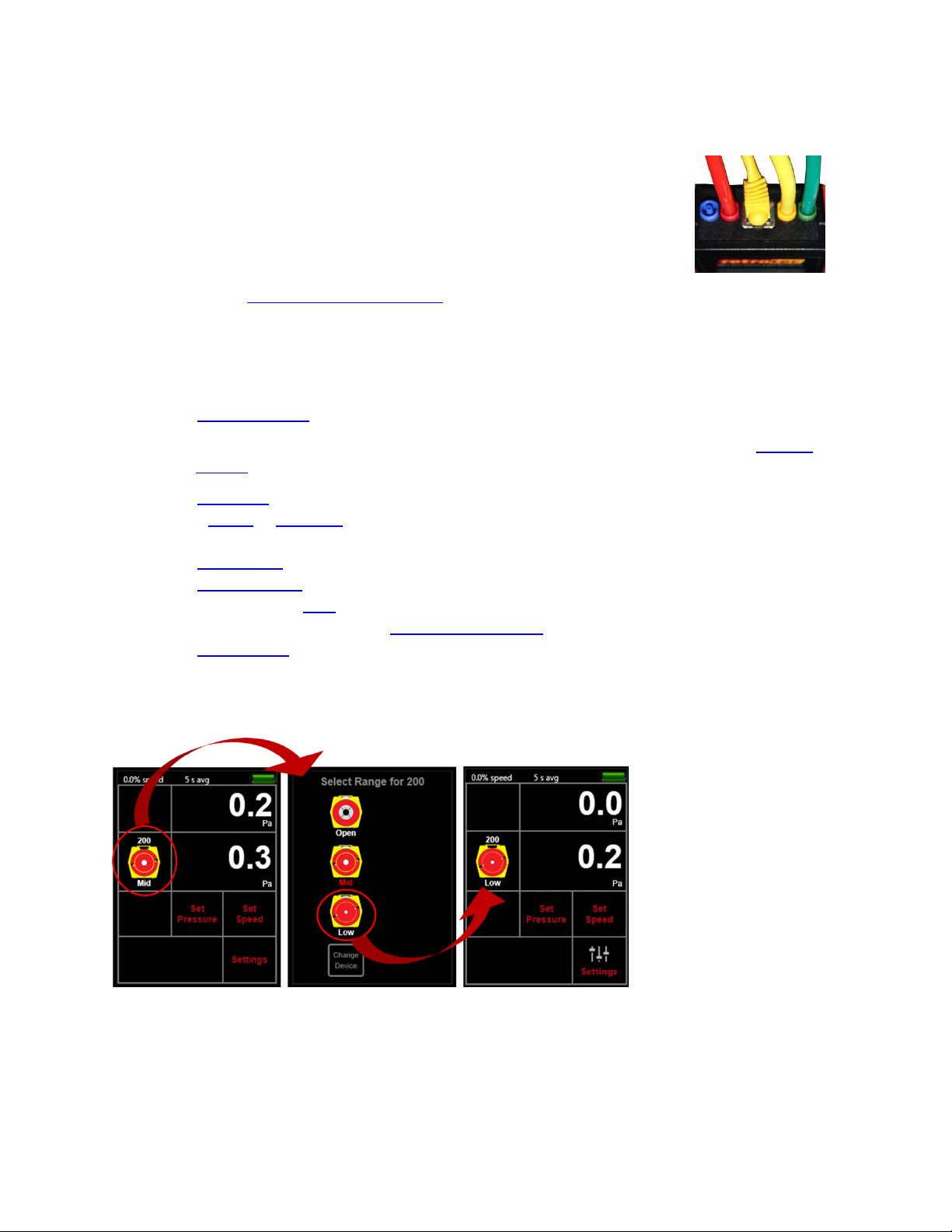
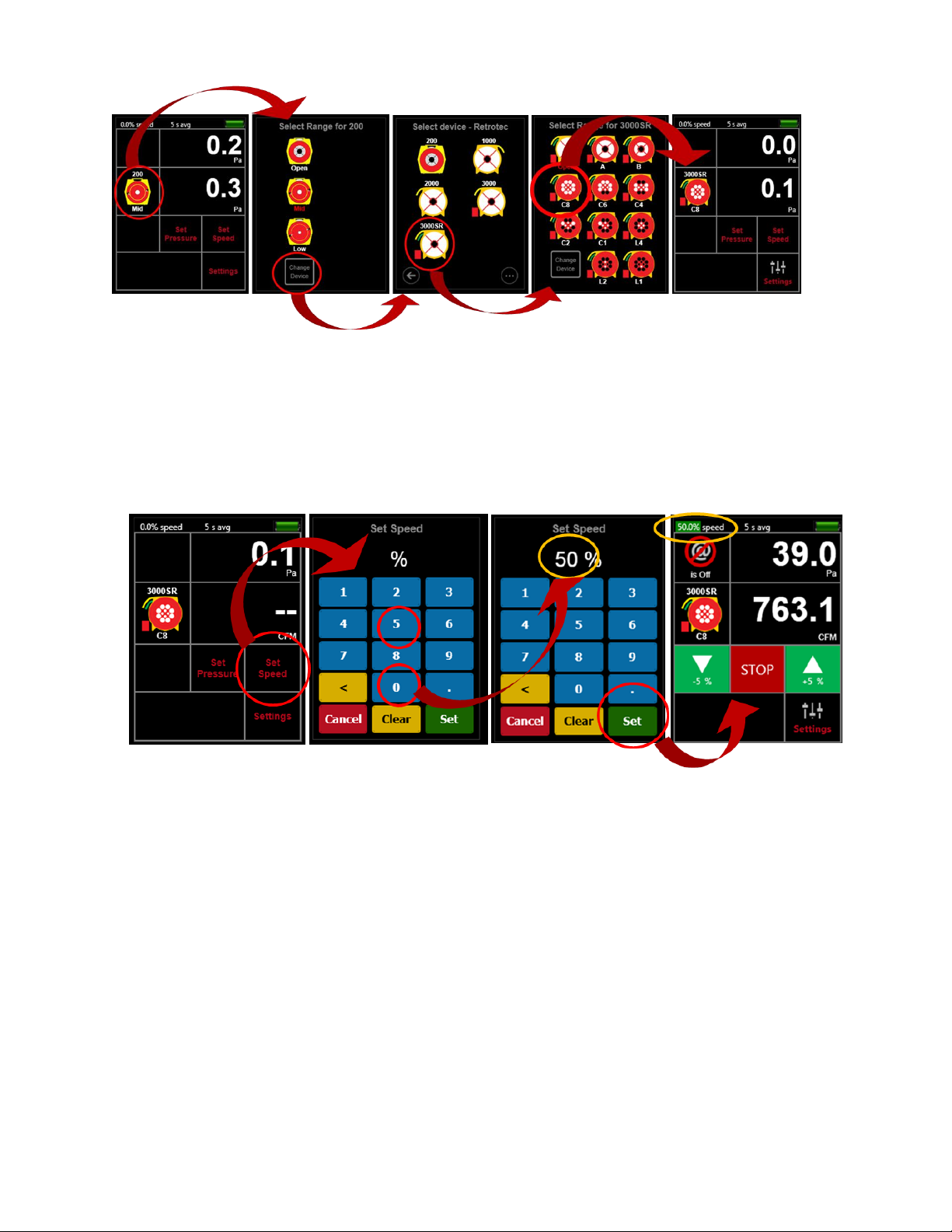
3.3.1. Tap [Range/Device] to match Range on Device in use
Figure 13: Change Range for selected Device
3.3.2. Tap [Range/Device] [Change Device] to change Device in use
Page 22 of 94
©Retrotec Inc. 2014
Figure 14: Change Device in use
3.3.3. Tap [Set Speed] to run the fan at a particular speed
The gauge can automatically control the fan speed on Retrotec systems to achieve a specific fan speed,
entered by the user.
Figure 15: Set gauge speed control output
Fans manufactured by TEC (such as the DuctBlaster or Minneapolis Model 3 or 4) can also be controlled if
an optional Retrotec-TEC speed control Adapter is connected between the gauge and the TEC fan in the
Speed Control cable as shown in Figure 12. Pressure tubing needs to be attached to the gauge using the
Retrotec conventions described in the Retrotec literature.
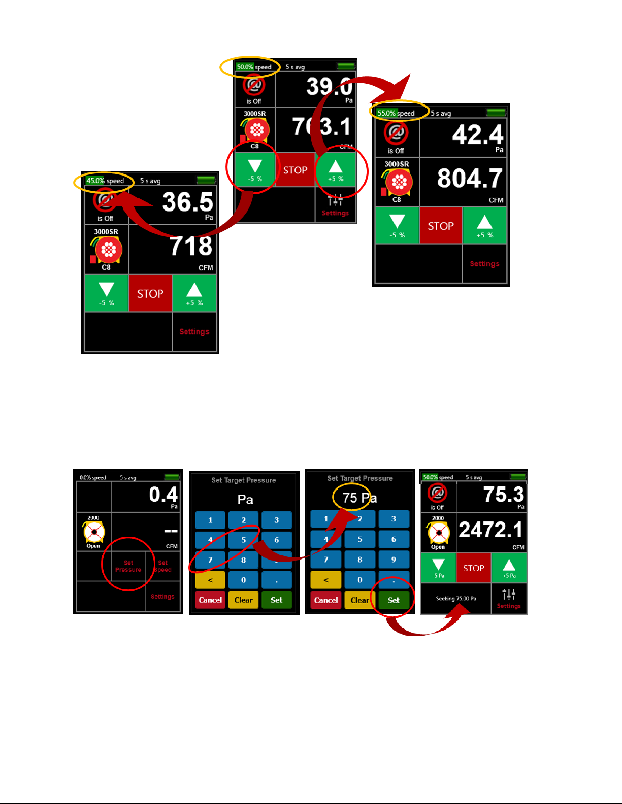
3.3.4. Tap [Jog] keys to adjust speed up or down 5%
Page 23 of 94
©Retrotec Inc. 2014
Figure 16: Adjust speed up or down 5% using [Jog] keys
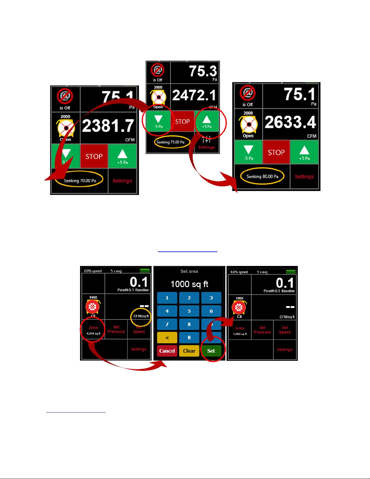
3.3.5. Tap [Set Pressure] to achieve a particular enclosure pressure
The gauge can achieve a target enclosure pressure entered by the user. The gauge controls pressure by
automatically adjusting the speed control output based on the pressure reading on Channel A. Retrotec
fans can be controlled directly from the gauge.
Figure 17: Set gauge to achieve target pressure
Fans manufactured by TEC can also be controlled if the optional Retrotec-TEC speed control Adapter is
connected between the gauge and the TEC fan as shown in Figure 12. Pressure tubing needs to be
attached to the gauge using the Retrotec conventions described in the Retrotec literature.
Page 24 of 94
©Retrotec Inc. 2014
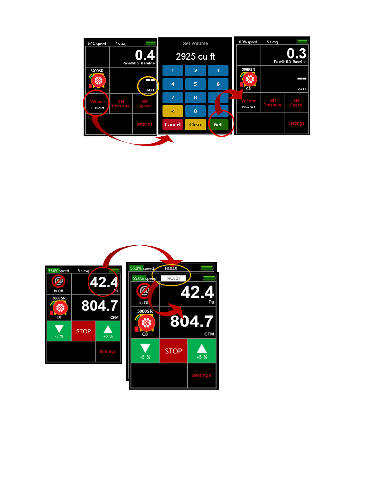
3.3.6. Tap [Jog] keys to adjust pressure up or down 5 Pa
Figure 18: Adjust pressure up or down 5 Pa using [Jog] keys
3.3.7. Tap [Area] or [Volume] to enter dimension for particular Results
The [Area] key only appears on the Home screen if one of the permeability results requiring an input of
area for the calculation is selected as the “Result to be displayed” on [Channel B].
Figure 19: Enter an [Area] if the Result to be displayed is calculated with an Area
The [Area] key from the Home screen opens the same screen as the [Settings][Area] key combination.
The [Volume] key only appears on the Home screen if “ACH” (Air Changes per hour) is selected as the
“Result to be displayed” on [Channel B].
Page 25 of 94
©Retrotec Inc. 2014
Figure 20: Enter a [Volume] if Result to be displayed is "ACH"
The [Volume] key from the Home screen opens the same screen as the [Settings][Volume] key
combination.
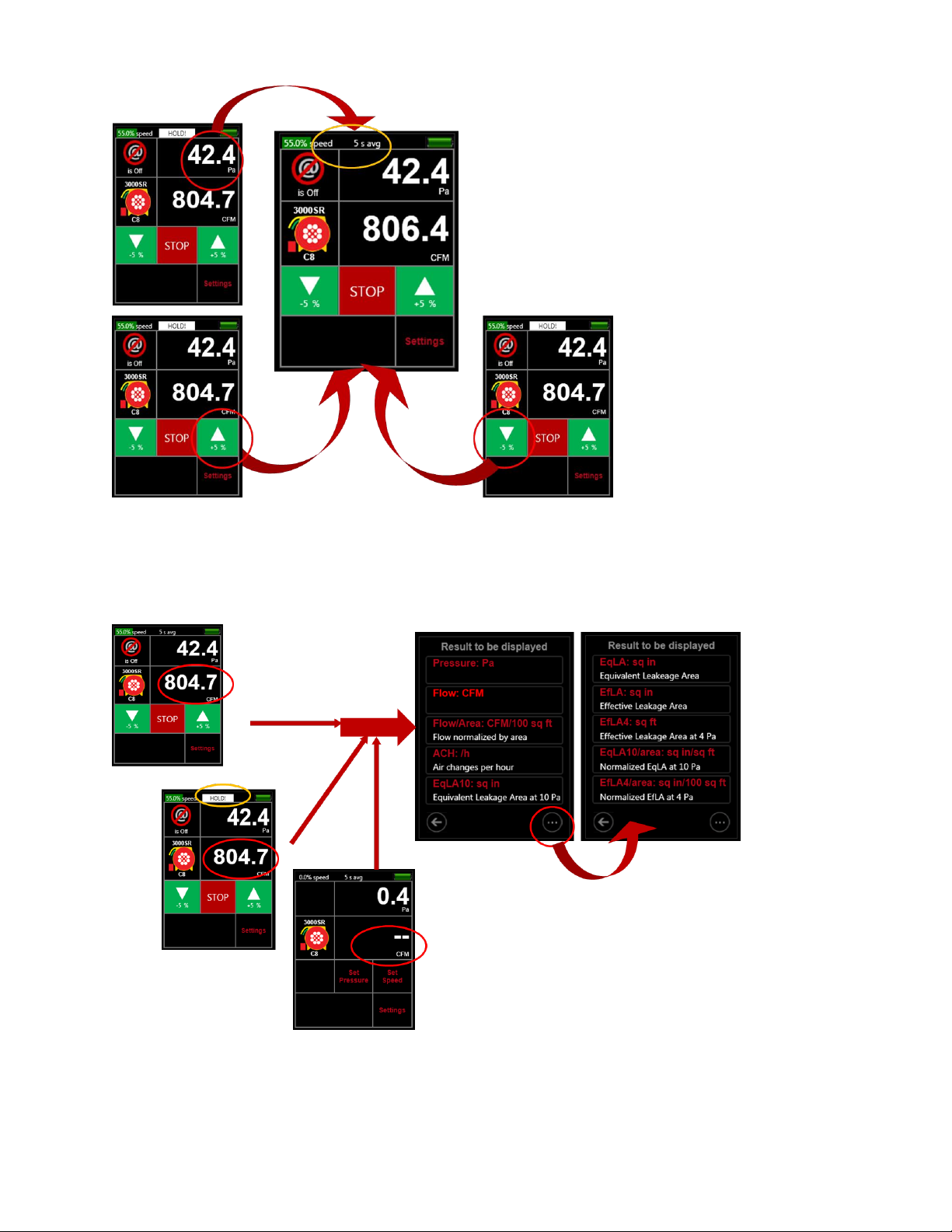
3.3.8. Tap [Channel A] to “Hold” readings and results
[Channel A] also acts as a key, so by tapping here, the results can be frozen at the value in place when the
key is tapped, called “Hold”. When active, you will see “Hold” displayed and flashing in the Top Bar. “Hold”
allows the user to copy results down without them changing and flashing. Changing the Result is even
available when display is frozen using “HOLD!”.
Figure 21: “HOLD!” Result on display by tapping [Channel A]
To remove “HOLD!” and release the display, tap again on [Channel A], or hit a Jog key.
Page 26 of 94
©Retrotec Inc. 2014
Figure 22: Remove "HOLD!" by tapping [Channel A] or a [Jog] key
3.3.9. Tap [Channel B] or [Settings] to change Result or units to be displayed
[Channel B] acts as a key, so by tapping it you can change the Result to be displayed at [Channel B]. The
Result to be displayed can also be changed by tapping on [Settings].
Figure 23: Change “Result to be displayed” during operation
Page 27 of 94
©Retrotec Inc. 2014
Changing the Result to be displayed can occur even while the fan is running during [Set Pressure] or [Set
Speed] so user can see multiple results for one fan speed setting. Changing the Result is even available
when display is frozen using “HOLD!”.
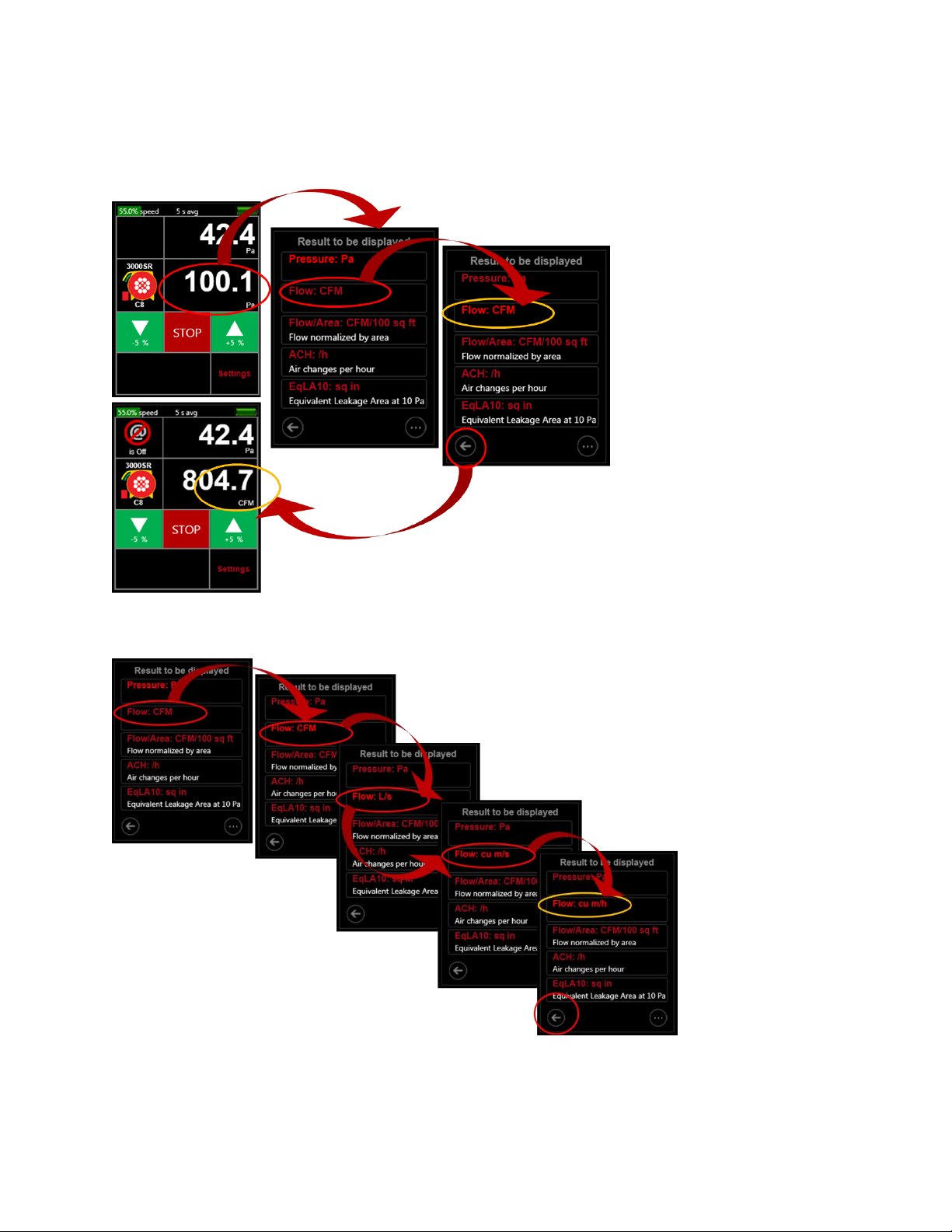
Figure 24: Tap [Channel B] to change “Result being displayed”
Each of the available results can be displayed with the user’s choice of units.
Figure 25: Change Flow result units from “CFM” to “cu m/h”
3.3.10. Tap [@ Pressure] to estimate Result at a different pressure
Page 28 of 94
©Retrotec Inc. 2014
When the gauge is controlling to a speed or pressure so that fan speed is not at 0%, the gauge can
extrapolate the Result and show a value for the Result that would have been achieved if the pressure on
Channel A had reached a different value. The “different value” mentioned is called the extrapolation
pressure or “@ Pressure”. If setting speed, the extrapolation pressure will be the “Default @ Pressure” the
user can enter in the second “Settings” screen. If setting pressure, the extrapolation pressure will be
exactly the target pressure.
If setting target pressure to zero, then the gauge does not allow @ pressure extrapolation to be used.
For mathematical details on @Pressure extrapolation, see Appendix D. For practical information on
extrapolation, see 2.6.4.
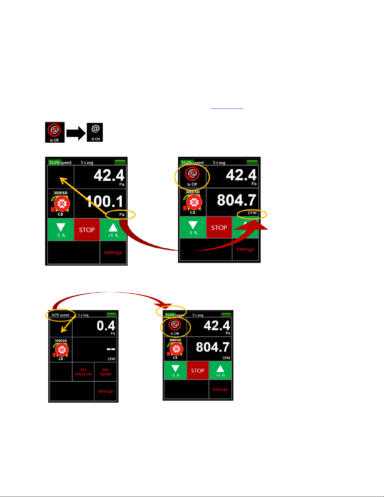
Figure 26: Turn [@ Pressure] on
Figure 27: [@ Pressure] is not available when Pressure is the Result on Channel B
Figure 28: [@ Pressure] is not available when the gauge is not actively controlling a fan
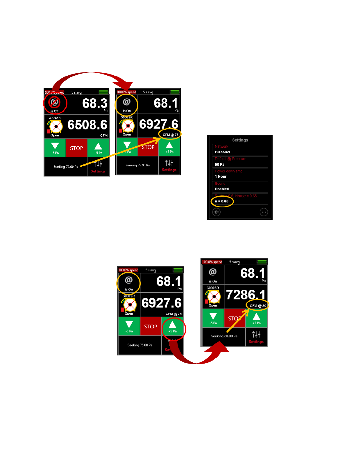
If [Set Pressure] function is used:
Page 29 of 94
©Retrotec Inc. 2014
Tapping [@ Pressure] so that it “is On” extrapolates the [Channel B] Result to the [Set Pressure]
target entered, using the “n” value specified in the second “Settings” screen.
Tapping a [Jog] key so that target pressure changes causes the “@ Pressure” label to change as
well.
Figure 29: [@ Pressure] extrapolates to the target pressure when a pressure is set
Figure 30: Jogging pressure while using [@ Pressure] changes target and @ pressure label
If [Set Speed] function is used:
Tapping [@ Pressure] so that it “is On” extrapolates the [Channel B] Result to the [Default @
Pressure] using the “n” value, both set in the second “Settings” screen.
 Loading...