


SA1/SA2/SAC1
Wirefree
Alarm Systems
1 |
2 |
3 |
|
4 |
5 |
6 |
|
7 |
8 |
9 |
1 |
0 |
|
|
2 |
LOW BATT.
Installation & Operating
Manual
FOREWORD
The SA1, SA2 and SAC1 Wirefree Alarm Systems comply with the requirements of BS6799 Class 1 for Wireless Alarms. All components are designed and manufactured to provide a high standard of security protection and long, reliable service. In addition, the radio devices are tested and approved by the Radio Regulatory division of the Department of Trade and Industry (DTI) to ensure that they will not interfere with other radio equipment. No radio licence is required, however, the approved radio frequency is not protected from interference and may be withdrawn from use at any time subject to the DTI giving users an appropriate notice period.
These Alarm Systems are designed for ease of installation using only conventional domestic tools. However, it is essential that the installer reads and fully understands the advice and procedures contained in this manual and plans the system before proceeding with the installation.
During installation, it is important that the procedures described in this manual are followed in sequence.
Note: This manual covers the installation and operation of a number of different kit configurations. Instructions relating to components not included in your kit should be ignored.
This manual should be retained in a safe place for
future reference.
IMPORTANT
All components, with the exception of the External Solar Siren are suitable for mounting in dry interior locations only.
Tools and Equipment Required: |
|
No.0 Philips Screwdriver |
Drill |
No.1 Philips Screwdriver |
Bradawl |
No.2 Philips Screwdriver |
Small Spirit Level |
5 & 6mm Masonry Drill Bits |
|
LOCAL AUTHORITY REGULATIONS
Depending on your location in the country, you may be required, by law, to notify the Local Authorities and Police of your new alarm installation.
Local Authority requirements differ from area to area, therefore, we recommend that you contact your Local Borough Environmental Officer to obtain full details of your area's requirements.
SYSTEM SECURITY
This system has been designed to both detect intruders and act as a strong deterrent to would-be intruders.
Please remember that given adequate knowledge and time it is possible to overcome any alarm system and we therefore recommend that an Intruder Alarm is used in conjunction with good physical protection such as security window and door locks.
All units in the system are encoded to operate together using an 8 bit House Code which is configured by the user/installer to provide the system security code for your installation. The system House Code can be changed at any time by the user.
IMPORTANT: All units forming part of your alarm system must be set to the same House Code.
The system is operated from one or more Remote Control units and/or Keypads. Care should be taken to ensure that your Remote Control Unit(s) are not lost or the Keypad User Access code does not become known to other people as this will compromise the security of your system. In either event the system house code and/or User Access code should be changed as soon as possible.
In order to detect any attempts to jam the radio channel used for your alarm system, a special jamming detection function is incorporated into the Solar Siren. If this feature is enabled, and the radio channel is jammed continuously for 30 seconds, (when the system is armed), the Solar Siren will emit a series of rapid bleeps for 5 seconds as a pre-alarm. If the jamming continues for a further 10 seconds or more a full alarm condition will occur.
SAFETY
Always follow the manufacturers advice when using power tools; steps, ladders etc. and wear suitable protective equipment (e.g. safety goggles) when drilling holes etc.
Before drilling holes in walls, check for hidden electricity cables and water pipes, the use of a cable/pipe locater maybe advisable if in doubt.
When using ladders, ensure that they are positioned on a firm stable surface at the correct angle and suitably secured before use.
The use of ear defenders is advisable when working in close proximity to the Siren due to the high sound level produced by this device.
Response |
|
SA1/SA2/SAC1 Wirefree Alarm Systems |
|
CONTENTS
|
Page No. |
KIT CONTENTS |
2 |
PLANNING AND EXTENDING YOUR WIREFREE |
|
SOLAR ALARM SYSTEM |
3 |
EXTERNAL SOLAR SIREN |
4 |
General Information |
4 |
Positioning the Solar Siren |
4 |
Installing the Solar Siren |
4 |
Configuring the Solar Siren |
5 |
Initial Power-up of the Solar Siren |
6 |
REMOTE CONTROL UNIT |
6 |
General Information |
6 |
Configuring the Remote Control |
6 |
Testing the Remote Control |
7 |
KEYPAD |
7 |
Positioning the Keypad |
8 |
Installing the Keypad |
8 |
Configuring the Keypad |
8 |
Testing the Keypad |
9 |
PASSIVE INFRA RED (PIR) |
|
MOVEMENT DETECTORS |
9 |
Positioning the PIR Movement Detectors |
9 |
Installing the PIR Movement Detectors |
10 |
Configuring the PIR Movement Detectors |
11 |
Testing the PIR Movement Detectors |
11 |
MAGNETIC CONTACT DETECTORS |
12 |
Positioning the Magnetic Contacts |
12 |
Installing the Magnetic Contacts |
12 |
Configuring the Magnetic Contacts |
13 |
Testing the Magnetic Contacts |
13 |
TESTING THE SYSTEM |
14 |
Initial Testing |
14 |
Testing An Installed System |
14 |
|
Page No. |
OPERATING INSTRUCTIONS |
14 |
System Service Mode |
14 |
System Operating Mode |
14 |
Arming The System |
14 |
Disarming The System |
15 |
Personal Attack (PA) Alarm |
16 |
Battery Monitoring |
16 |
MAINTENANCE |
16 |
ALARM RECORD |
17 |
TROUBLE SHOOTING |
18 |
EXTENDING YOUR ALARM SYSTEM |
20 |
COMPONENT SPECIFICATION |
Back Cover |
SA1/SA2/SAC1 |
|
1 |
|

KIT CONTENTS
The Alarm System should contain the following
components.
Alarm System |
SA1 |
SA2 |
SAC1 |
|
|
|
|
External Solar Siren Controller |
1 |
1 |
1 |
|
|
|
|
Remote Control |
1 |
1 |
1 |
|
|
|
|
PIR Movement Detectors |
2 |
2 |
2 |
|
|
|
|
Magnetic Contact Set |
0 |
2 |
2 |
|
|
|
|
Keypad |
0 |
1 |
1 |
|
|
|
|
Also included:
Installation & Operating Manual
Fixing pack
Batteries
|
|
|
|
|
Sealed lead acid battery |
9V PP3 Alkaline |
3V CR2032 |
||
6V/1.2Ahr |
battery |
Lithium Cell |
||
(for Solar Siren) |
(for Keypad and |
(for Remote |
||
|
PIR Detector) |
Control |
||
|
|
|
|
and Magnetic |
|
|
|
|
Contact Sets) |
IMPORTANT
Please check all items are present BEFORE breaking open the packaging clamshell. No claims for missing parts will be accepted unless the clamshell is unopened and intact.
EXTENDING THE ALARM SYSTEM
The following additional accessories are available to
enhance your system and provide further protection
and a higher level of security where required.
Component: |
Product Code |
Two Magnetic Contact Sets |
|
and one Remote Control |
SU1 |
Two Passive Infra-Red |
|
Movement Detectors |
SU2 |
Two Remote Controls |
SU3 |
Full details of these accessories are given on page 20.
External Solar Siren Controller
1 |
2 |
3 |
|
4 |
5 |
6 |
|
7 |
8 |
9 |
1 |
0 |
|
|
2 |
LOW BATT.
Keypad
Magnetic
Contact Set
PIR Movement |
Remote |
Detector |
Control |
2 |
|
SA1/SA2/SAC1 |
|

PLANNING AND EXTENDING YOUR WIREFREE ALARM SYSTEM
The following example below shows typical property incorporating the suggested positions for the External Siren, Keypad, PIR and Magnetic Detectors for optimum
security. Use this as a guide for your installation in conjunction with the recommendations contained in this manual for planning your intruder alarm system.
1 |
2 |
3 |
4 |
5 |
6 |
7 |
8 |
9 |
0 |
|
ON AIR |
|
|
LOW BATT. |
Before attempting to install your Alarm System it is important to study your security requirements and plan your installation.
The alarm system may be extended to provide even greater protection by fitting additional PlR Movement Detectors and Magnetic Contact Detectors as required.
SA1/SA2/SAC1 |
|
3 |
|
EXTERNAL SOLAR SIREN
The Siren and Solar Panel are all encapsulated within a tough polycarbonate housing. This housing provides full protection against adverse weather conditions. All electronic components are specially treated to ensure long, reliable, trouble free operation.
An LED Strobe unit is built into the siren to act as a visible deterrent/indication that the system is active. The Strobe LEDs will slowly and alternately flash whether the system is Armed or Disarmed. During an alarm condition the Strobe LEDs will flash rapidly.
An integral anti-tamper switch provides additional security protection to the Siren should any unathorised attempt be made to interfere with and remove the siren cover.
The Siren is powered by a high capacity 6V/1.2Ahr rechargeable sealed lead acid battery. A Solar Panel mounted on the top of the housing charges the battery during daylight hours.
An 9V Alkaline PP3 battery is supplied in the External Siren to boost the initial power to the unit when the system is first activated until the Solar Panel charges the main battery.
The Siren unit incorporates the installations Jamming Detection system which will (if activated) generate an alarm if any attempt is made to continuously jam the radio channel used for the system.
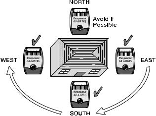
POSITIONING THE SOLAR SIREN
The Siren should be located as high as possible in a prominent position so that it can be easily seen and heard. The Siren should be mounted on a solid even surface so that the rear tamper switch is not activated when mounted. Ensure that the tamper switch does not fall into the recess between brick courses as this could prevent the switch from closing.
To provide the optimum amount of daylight to the Solar Panel, you should ideally mount the Solar Siren on a south facing wall. However, an easterly or westerly position will suffice.
Although the Solar Siren is designed to work on any aspect wall, for optimum performance you should refrain from siting the unit on a north facing wall, where possible.
Shadows cast by neighbouring walls, trees and roof overhangs should also be avoided. If the Siren is to be mounted below the eaves, it should be positioned a
distance of at least twice the width of the eaves overhang below the eaves. Remember that in winter the sun is lower in the sky and you should avoid winter shadows where possible.
The External Solar Siren contains a sophisticated radio receiver. However, reception of radio signals can be affected by the presence of metallic objects within the vicinity of the Receiver. It is therefore important to mount the Solar Siren a minimum distance of 1m away from any external or internal metalwork, (i.e. drainpipes, gutters, radiators, mirrors etc).
It is recommended that you check the suitability of your chosen location for the Solar Siren by temporarily fitting it to the external wall. Using the Remote Control, (as described below) power up the Siren and check that you can operate the Siren from in and around the property, and from all locations where you plan to install detectors.
INSTALLING THE SOLAR SIREN
1.Remove the fixing screw from the bottom edge of the Siren housing and carefully hinge off the front cover. All electronic components are housed within the front cover.
2.Hold the mounting plate in position and mark the positions of the four mounting holes. A spirit level placed on the casing will ensure a perfect level. Drill four 6mm holes and fit the wall plugs.
3.Fit two 30mm fixing screws in the top holes leaving approximately 10mm of the screw protruding.
4.Fit the top keyhole slots of the mounting plate over the screw heads. Remove the mounting plate and adjust the screws until they form a neat fit with the mounting plate with minimal movement.
5.Secure the mounting plate in position using two 25mm fixing screws in the bottom fixing holes.
4 |
|
SA1/SA2/SAC1 |
|

CONFIGURING THE SOLAR SIREN
Solar Panel
Receiver
Aerial
Tamper
switch
6 Volt 1.2Ahr rechargeable
battery
9 Volt PP3 initial power up battery
Main Configuration
Switch (in C.U. Position)
C.U. |
SIREN |
Front cover
locating tabs 7.5 Volt DC charging adaptor
input
Dip switch
cover
Bleep Disable Link
Siren Disable Link
Jamming
Detection Link
Printed circuit
House Code
board enclosure
dip switches 1-8
Alarm duration
Optional Strobe dip switch 9
Upgrade PCB
C.U. |
SIREN |
Ensure that the Solar Siren main configuration switch on the LED strobe board is set to "C.U." for use with this alarm system.
Undo the 3 screws holding the DIP Switch Cover in place and remove the cover.
HOUSE CODE
Under the cover you will find a series of 9 DIP switches.
View of inside
Siren |
Solar Siren |
|
BEEP DISABLE
The Solar Siren will acknowledge signals from the Remote Control by beeping. It is possible to disable the beeps if required by removing the jumper link P2 on the circuit board.
SIREN DISABLE
If for any reason you need to disable the Siren, remove jumper link P3 on the circuit board. This will prevent the Siren from sounding during an alarm condition. However, the Siren will still beep to acknowledge signals from the Remote Control, (provided the beep feature is not disabled).
Select and record a random combination of ‘ON’ and ‘OFF’ positions for DIP switches 1- 8. This will be the system House Code that will enable all devices on the system to communicate with the Solar Siren.
IMPORTANT: The house code for your system should be changed from the factory default settings.
Note: When the Solar Siren is viewed as shown above (Solar panel at top) the DIP switches are ‘upside down’.
ALARM DURATION
This is the length of time that the alarm will sound for, following activation. The Alarm duration can be set for either 1 or 3 minutes using DIP switch 9 as follows:
ON |
= |
3 minutes |
OFF |
= |
1 minute |
If accidentally triggered, the alarm can be stopped at any time using the Remote Control.
JAMMING DETECTION DISABLE
To enable the Jamming Detect feature fit the jumper link taped to the cover of the Siren control unit across link pins P1 on the circuit board.
Note: The Jamming Detection circuit is designed to permanently scan for jamming signals. However, it is possible that it may detect other local radio interference operating legally or illegally on the same frequency. If it is planned to operate the jamming detection feature we recommend that the system is monitored for false jamming alarms for at least 2 weeks prior to leaving the Jamming Detection function permanently enabled
Once you have completed setting your House Code and system features, refit the DIP switch cover and replace the three cover fixing screws. Do not over tighten the screw as this could damage the thread.
SA1/SA2/SAC1 |
|
5 |
|

INITIAL POWER-UP OF THE
SOLAR SIREN
1.Connect the 9V PP3 initial power battery to the battery clip.
Connect the rechargeable battery to the charging leads. Connect the Red lead to the Red (+ve) terminal and the Black lead the Black (-ve) terminal.
Note: Once the batteries have been connected, the unit will be operational and it is important that the solar panel receives sufficient light to maintain the battery charge. The unit should not be repeatedly set into alarm during installation/ testing, as this will rapidly drain the battery.
2.Press the anti tamper switch, the LEDs will flash together to indicate that the unit is operational.
3.Hinge the front cover locating tabs over the top edge of the back plate and carefully push the base of the siren cover into place. Secure the Siren cover in place by refitting the fixing screw in the bottom edge of the cover. Do not over tighten the screw as this could damage the thread.
IMPORTANT: Ensure that the rear tamper switch is closed when you fit the siren cover to the backplate (i.e. listen for the switch to click). If the switch does not close this will prevent the Solar Siren from operating correctly. If necessary, remove the siren cover again and adjust the screw on the back-plate tamper plunger to ensure the switch closes when the Siren is secured in position.
4.If fitted remove the protective film covering the Solar Panel.
5.The fitting of the Solar Siren is now complete and the unit is automatically in Service Mode.
While in Service Mode the Solar Siren will not acknowledge any signals from Detectors, Personal Attack Buttons, Tamper Switches etc. Service Mode is controlled from the Remote Control - refer to page 14 for details.
REMOTE CONTROL UNIT
The Remote Control Unit is used to Arm and Disarm the system. The Remote Control can arm the system in either Instant or Delay modes.
Arm/ |
Transmit LED |
|
|
Instant-Arm |
|
Part-Arm/ |
Slide up |
Delay-Arm |
to operate |
Disarm |
Personal Attack |
The Remote Control Unit also incorporates a Personal Attack (PA) switch. Activating the PA switch on the side of the Remote Control will immediately initiate a Full Alarm condition whether the system is Armed or Disarmed. The alarm can be cancelled by pressing the ‘DISARM’ button on the Remote Control.
Any number of Remote Control Units can be used with your system, providing they are all coded with the system House Code.
The Remote Control is powered by a CR2032 type Lithium cell which under normal conditions will have an expected life in excess of 1 year. Under normal battery conditions the LED on the Remote control will only illuminate when a button is pressed. However, under low-battery conditions this LED will continue to flash after the button has been released. When this occurs the batteries should be replaced as soon as possible.
CONFIGURING THE REMOTE CONTROL
1.Remove the rear cover by undoing the small screw on the rear of the Remote Control.
2.Located above the battery cover is a row of 8 DIP switches. These switches set the House Code for the Remote Control and must be set to the same ON/OFF combination as the House Code DIP switches in the Solar Siren.
3.Ensure that the jumper link located immediately below the House Code DIP switches is removed for use with this alarm system.
4.Insert the battery under the clip ensuring that the +ve terminal faces upwards away from the PCB.
6 |
|
SA1/SA2/SAC1 |
|
 Loading...