

Page 1
Introduction
When connected to the RE5000 Control Unit, the
RE5000AD may be used to communicate up to three
separate message phrases (usually relating to Intruder,
Fire and Medical Alert conditions). The Dialler Tamper
Switch may be connected to Zone 6 on the RE5000CU
if tamper protection is required.
The Communicator Interface Cable connection supplied
with the RE5000 Control Unit allows simple connection
between the Control Unit and Dialler.
THE FOLLOWING MUST BE READ IN CONJUNCTION
WITH THE RE5000AD (TSD1+) INSTALLATION AND
OPERATING INSTRUCTIONS SUPPLIED AND THE
RE5000 INSTALLATION AND OPERATING MANUAL.
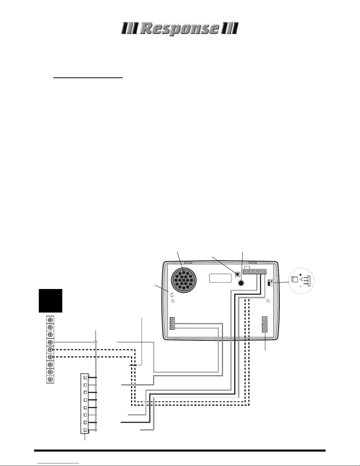
CONNECTING THE RE5000AD TO
THE RE5000 CONTROL UNIT.
1.
Disconnect all power (Mains and Back-up Battery)
from the Control Unit before making any connections.
2. Plug the Interface Cable into the Control Unit plug
and connect the lead to the Dialler as shown.
3. Ensure that all cabling is connected correctly and that
all unused cores of the Interface Cable are cut back or
insulated to prevent accidental short circuits.
4. Connect the Telephone Cable to the Dialler - (see
Dialler Installation Instructions).
5. Reconnect power to the Control Unit and proceed to
programme and test the Dialler in accordance with
the Dialler Operators Manual.
Note:
If your RE5000CU is supplied with an 8-Core
interface cable, please call our Technical
Helpline for connection advice.
Loudspeaker
Tamper
Switch
Microphone
Set Trig Polarity
Link to '+' for
negative trigger
to suit RE5000CU
trigger output
Te lephone Line
Connection Terminals
Factory
Restart Pins
Factory Restart
0/P1
0V
+12V
TRIGGER
POLARITY
A B A1 B1
TELEPHONE CONNECTIONS
TAMP ABORT C B A
TRIG INPUT
TSD1
+
Optional Dialler Tamper Connection
To Zone 6 Hard Wired Zone Input
on RE5000CU
9-Core Interface Cable
Red +12V
Blue
Grey
Brown
Orange
Yel low
Green
Mauve
White
AC Power
Failure
– 0V
Arm
Disarm
Low Batt
Intruder
Fire
Medical Alert/
Personal Attack
Control Unit
Terminal Block
Plu
g
-in Connector to Control Unit PCB
N.O.
COM
N.C.
V+
GRD
Zone 6
Siren
Charge
Ta mper
Communicator
Interface Cable
Connection
Connections for 9-Core Interface Cable
9
CORE
Using the RE5000AD with a
RE5000 System Control Unit
Installation and Operating Instructions
Page 2
Introduction
When connected to the RE3000 Control Unit, the
RE5000AD may only be used to communicate one
message phrase associated with the Alarm Activation (usually relating to an Intruder Alarm Condition).
This message phrase will be made up of the common
phrase O and message phrase A. Message phrases B,
C and D will not be used in this instance.
THE FOLLOWING MUST BE READ IN CONJUNCTION
WITH THE RE5000AD (TSD1+) INSTALLATION AND
OPERATING INSTRUCTIONS SUPPLIED AND THE
RE3000 INSTALLATION AND OPERATING MANUAL.
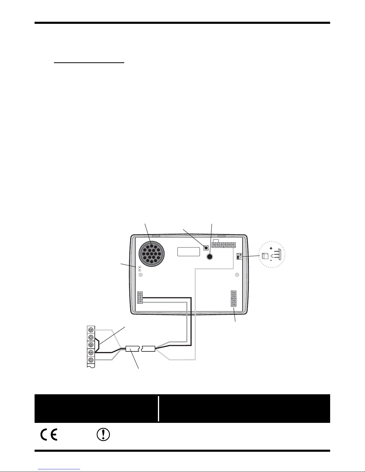
CONNECTING THE RE5000AD TO THE
RE3000 CONTROL UNIT.
1. Disconnect all power (Mains and Back-up Battery)
from the Control Unit before making any connections.
2. Connect the 4 core cable supplied with the Dialler to
the Control Unit as shown.
3. Ensure that all cabling is connected correctly. Cut
back or insulate any unused cable cores to prevent
short circuits.
4. Connect the Telephone Cable to the Dialler - (see
Dialler Installation Instructions).
5. Reconnect power to the Control Unit and proceed to
programme and test the Dialler in accordance with
the Dialler Operators Manual.
Loudspeaker
Tamper
Switch
Microphone
Set Trig polarity Link to '–'
for negative trigger to suit
RE3000CU trigger output
Te lephone Line
Connection Terminals
Factory
Restart Pins
Red
Black
Yellow
Terminals inside
RE3000 Control Unit
NO 1
C 2
NC 3
Power (–) 4
Power (+) 5
4-Core Cable
(Blue wire not used)
Install link wire between
terminals 2 and 4
Red
Black
Yellow
Factory Restart
0/P1
0V
+12V
TRIGGER
POLARITY
A B A1 B1
TELEPHONE CONNECTIONS
TAMP ABORT C B A
TRIG INPUT
TSD1
+
Using the RE5000AD with a
RE3000 System Control Unit
WA_08.04 CA2000AD
Wireless Alarms. 17Church Road, Great Bookham, Surrey KT23 3PG
Telephone: 01372 450960 E-mail: info@wireless-alarms.net www.wireless-alarms.net
0359
RADIO DEVICES FOR USE IN THE UK
HELPLINE
If you need help, just dial for
expert technical support
01372 450960
(Lines open 9.00am to 6.00pm, Monday to Friday).
 Loading...