

Page 1
Installation and Operating Instructions
These instructions should be retained in a safe place for future reference.
Page 2

2
CONTENTS
1. PLANNING YOUR LAYOUT (3)
2. KIT CONTENTS (5)
3. INSTALLATION (8)
4. CAMERA SETUP (9)
5. ABOUT DIGITAL WIRELESS TECHNOLOGY (12)
6. PRODUCT SPECIFICATION (13)
Page 3
3
PLANNING YOUR LAYOUT:
SAFETY AND INSTALLATION TIPS:
DVR
• keep away from heat sources and high temperature places
• Avoid direct sunlight
• Avoid humid places
• avoid vibration
• Install in a ventilated environment
• do not replace the supplied 2GB memory card with a greater capacity(the unit may
fail to operate properly).
TV/Monitor
Receiver
DVR
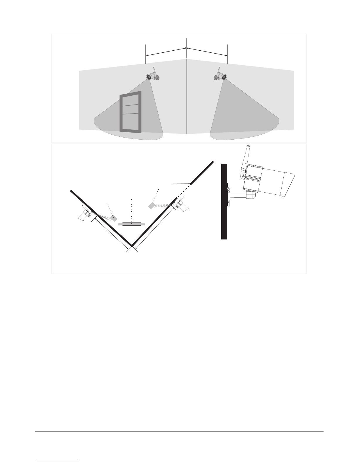
Front Door
Camera 2
Camera 1
Max 5m
Max 5m Max 5m
Max 5m
Ensure the distance from camera to power
outlet does not exceed the length of the
camera power adapter cable
15mm diameter
cable hole
(to allow camera
cable and connector
to pass through)
Page 4
4
Camera(s) and DVR
NIGHT VISION:
Do not attempt to open the units with the power adaptor plug connected to avoid any risk
of personal injury.
When installing CCTV camera(s), always foloow manufacturer's advice when using
power tools, steps, ladders, etc. and wear suitable protective equipment (e.g. safety
goggles)when drilling holes. Before drilling holes through walls check for hidden
electricity cables and water pipes. The use of cable/pipe detector is advisable.
It is also advisable to avoid exposing any cameras to extreme weather conditions (e.g,
under a gutter which is prone to any water leaks). When installing any cameras with this
unit, it is advisable to use cable conduit to protect any video/power extension cables
from being exposed externally and to prevent/reduce the chances of the cables being
tampered with. After drilling any hole though an external wall for a cable, ensure the hole
is sealed up around the cable using a sealant to prevent drafts.
To prevent a re or electrical shock hazard, do not attempt to open the housing while
the unit is exposed to rain, water or wet conditions. There are no user serviceable
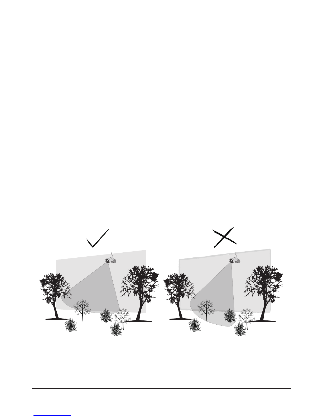
parts inside. Refer servicing to qualified service personnel. Avoid pointing the
camera(s) directly at the sun or any bushes, tree branches or moving objects that might
unnecessary cause the DVR to record due to winds for example. System also provides
"Masking" function, user may screen out motion detection area in parts of the picture
which motion detection is not required.
The camera has built-in infra-red LEDs to allow you to view at night for 24hrs
surveillance. The LEDs will automatically activate at night and the picture viewed will turn
to black and whit. The night viewing range is up to 7m.
Page 5

5
x Digital Wireless Camera
A
B
x 5V/1A Power Adapter
C
x Camera Stand
D
x )L[LQJ3DFN
E
x Camera Antenna
F
x Manual
Tools Required:
Electric drill
5mm masonry drill bit
15mm masonry drill bit
No. 2 Philips screwdriver
KIT CONTENTS
Page 6

6
A
B
Digital Wireless Camera
C
5V/1A Power Adapter for
Camera and Receiver
D
)L[LQJ3DFN
Camera Stand
E
F
Camera Antenna
Manual
Digital Wireless Colour Camera
Recordable CCTV Kit
Installation and Operating Instructions
YOUR HELPLINE 0844 736 9149
www.friedland.co.uk
Lines open Monday to Friday 9.00am to 5.00pm. Calls charged at local rates.
These instructions should be retained in a safe place for future reference.
Page 7

7
Setting the Camera Channel
Pairing the Camera to Receiver (Optional)
The wireless monitor support up to 4 wireless cameras. Follow the step below to set or
change the monitor channel of the camera. If you are adding another camera to link with the
supplied monitor in this kit, then ensure its channel is set to a different channel to the existing
camera(s).
Follow the steps in CAMERA SETUP section
to set or change the channel of the camera. If
you are adding another camera to link with the supplied receiver in this kit, then ensure its
channel is set to a different channel to the existing camera(s).
Pairing Key
INSTALLATION
Page 8

8
Attach Stand to Mounting Surface
A.Secure camera stand on the wall
B. Loosen up the Thumb screw
C.Adjust proper view angle then secure the joint with T-bolt.
C
B
CAMERA INSTALLATION
Page 9

9
Select CAMERA SETUP, press MENU key once to enter sub-menu.
CAMERA SETUP
Use▼▲to select the camera to set up (1-4).
Use◄►to select [PAIRING] [BRIGHTNESS] [CAMERA ON/OFF]
Page 10

10
Camera Pairing
With PAIRING section highlighted, press MENU key once to begin camera pairing (pair
LED on camera will blink once and following with LED blinking continuously indicating
data transmission in process.
System will conrm pairing process is successful with "PAIRED" displaying on screen.
System will indicate pairing process failed with "PAIRING FAIL" displaying on screen.
Press ESC to return to main menu.
With BRIGHTNESS section highlighted, use ▼▲ to adjust camera brightness.
Press ESC to return to main menu.
Camera Brightness Adjustment
Page 11

11
With ACTIVATION section highlighted, use ▼▲ to enable or disable camera.
Press ESC to return to main menu.
NOTE:
Make sure camera(s) paired is enabled for SCAN or QUAD to function properly
(camera "ON" can only be selected when camera has been paired to system.).
Camera Activation
Page 12

12
About Digital Wireless Technology
This section offers some helpful in for mation to overcome most of the
problems you may encounter. We hope this section can help you to enjoy
a pleasant setup.
Problems Diagnosis
About 2.4GHz Digital Wireless Signal
How to improve the wireless signal quality?
Why Image Compression?
This innovative digital wireless solution integrates advance Frequency
Hopping Spread spectrum (FHSS) technology. This technology greatly
reduce the interference that comes from other devices using the same
radio frequency (2.4GHz), e.g. WIFI, Bluetooth, Zigbee, cordless
phone...etc. You now can enjoy a more pleasant wireless surveillance
quality without flicking and noisy image. However, weaker signal (lag
or still image) can be observed yet from time to time, depending on the
environment where the sysgtem is installed.
complied with FCC part 15.247,ETSI(EN)300 328, audio / video signals
transmitted out about or over 500 foot / 150metre in line of sight should
be supported. Line of sign installatiom, though, is usually not a common
practice. Factors affecting transmission include microwave ovens or other
high frequency electromagnetic waves. Reinforced concrete walls, large
scale metal products and metal furniture should not be located near the
camera or the receiver. Water creates an obstacle and should not be
placed neqr. Human bodies such as a person passing through may cause
unstable signal quality
If possible, remove obstacles in between cam era and receiver that might
reect the signal. These could include fumiture, cabinets, and walls. If you
feel the wireless signal is not improvement. Or simply relocate the camera
closer to the receiver.
In order to provide a private and interference free wireless service,
this digital wireless solution works on a 2Mb narrow hopping band,
Different from traditional 2.4GHz analog signal, this digital wireless signal
is compressed and presented as Motion JPEG(MJPEG) format. By
digitalizing and compressing the raw analog data, the bandwidth is used
more efficiently and securely. Consequentially, you might observe an
indent image line on a larger display monitor or plasma TV.
Page 13

13
Product Specication
Camera
Maximum Channels 4
Communication Range 150 metres in open space
Monitor Resolution 800X480
Camera Resolution 640X480
Operating Temperature -10°C ~ 50°C
Operating Voltage DC 5V / 1A
Curren Consumption 550mA(max)
Night Vision 5m
Dimension 123x65x65 mm
 Loading...