

Page 1
GlobalGuard Wire less Indoor
IP Camera
Installation and Operating Manual
Page 2

2
IMPORTANT PLEASE READ BEFORE YOU START
DECLARATION
Novar ED&S hereby declar es that the wireless IP camera is in com pliance with the ess ential
requirements and other relevant provisions of the R&TTE directive (1999/5/EC).
Your camera’s unique “MAC ID” is printed on a small label applied to the rear of the camera.
You will need this to view the camera. You can also copy the “MAC ID” to page 25 of
this manual for security record purposes
Please also store this manual away in a safe place for future reference.
System requirements:
PC Operation System: Windows XP/Vista/Windows 7
Internet Explorer 6.x or higher Internet Web Browser
(Note: The IP camera requires IE Explorer for viewing the video
CPU: Pentium 4, 1GHz or above
VGA Card Resolution: 800x600 or above
Video Memory Size: 128Mb or above
Internet bandwidth: 512kbps recommended upload speed per camera
SD card for recording: Minimum 2GB/Maximum 3 2GB
Note: This camera requires a
GlobalGuard wireless alarm system to be set up in
advance. Please ensure that you already have the system set up in advanced and have
created an online web account.
Installation notes and tips:
Always follow manufacturers advise when using power tools, steps, ladders, etc and
wear protective equipment (e.g, safety goggles and gloves) when drilling holes, etc.
When using ladders ensure they are positioned on a firm stable surface at an angle and
suitably secured. Check for hidden electricity wires or water pipes before drilling any
holes. If in doubt use a cable/pipe locator.
This camera is designed for indoor dry use only. After drilling any holes through a wall
for a cable(s), ensure the hole is sealed up using a suitable sealant to prevent drafts.
To prevent a fire or electrical shock hazard, do not attempt to open the housing. Do not
expose the camera to weathering.
There are no user serviceable parts inside. Refer servicing to qualified service
personnel.
Please read before you start:
Always use discretion when installing CCTV equipment especially when there is
Page 3
3
perceived policy. Enquire regarding local applications to the lawful installation of
video recording/surveillance. Third party consent may be required.
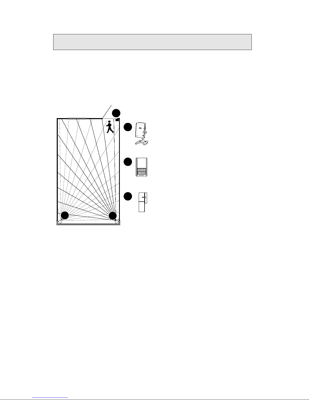
The camera should be position in view of a security detector such as a PIR movement detector
or a door/window contact detector. This is because the camera has the ability to record video
after a detector has been triggered by an intruder provided the camera has been setup with
same location setting as the security detector(s).
The open field wireless operating range of the camera is approximately 100m. The amount by
which the wireless range will reduce depends on the obstruction between the camera and your
wireless router:
Wall Type Range Reduction
Dry-lined partition wall: 10 - 30%
Single layer brick wall: 20 - 40%
Double layer brick wall: 30 - 70%
Metal panel/radiator: 90 - 100%
Note: The effect on the range of multiple walls is cumulative, i.e. if there are 2 brick walls in the
way, the range will be reduced by up to 40% by each wall.
ROOM
Door
A
A
B
B
C
C
PIR Movement
Detector
IP Camera
Magnetic
Door/Window
Detector
Example
When an intruder breaks
in the house and
triggers the PIR (B) or
magnetic door/window
detector (C), the camera
(A) will start recording
video provided it is set
to same location setting
at either of those
detectors
Page 4
4
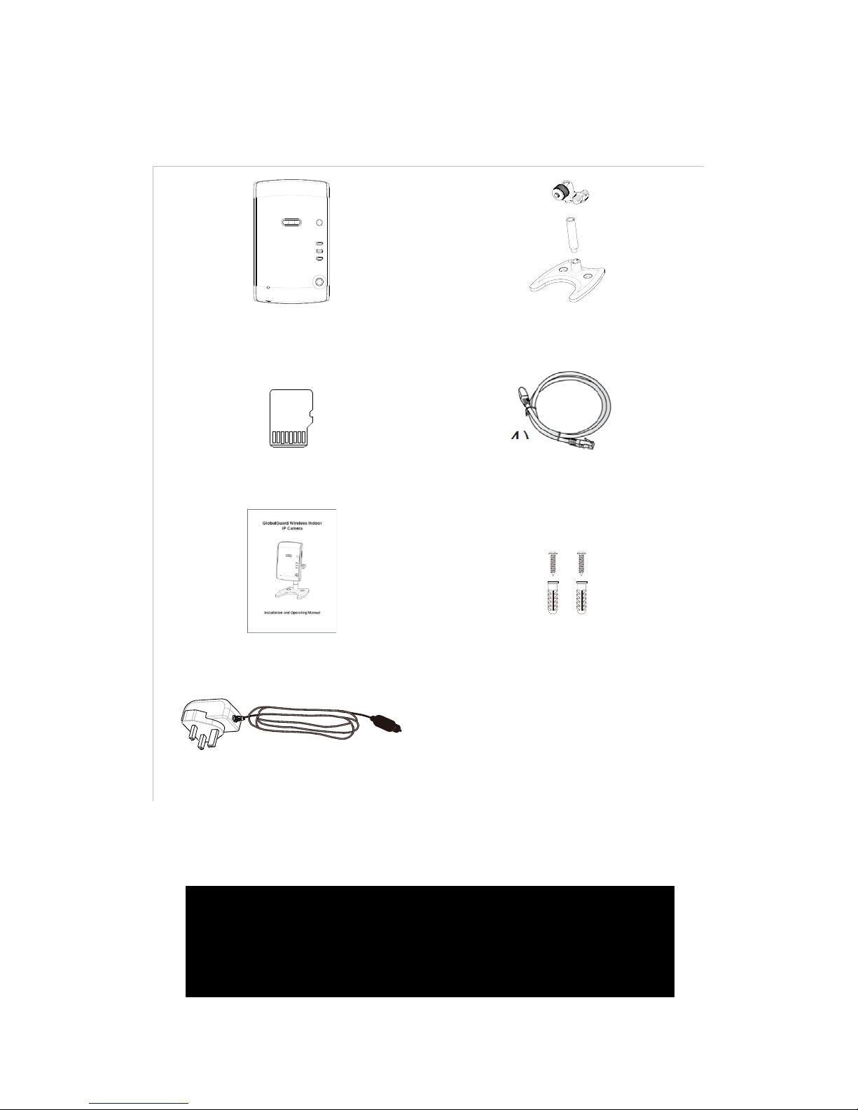
1. Introduction
1.1. Pack Contents
IP Camera
Bracket
Micro SD Card *
0.5m Ethernet Cable
User Guide
Screws and Wall Plugs
5V DC Power Supply Adapter
* You can use micro SD cards of greater storage (up to 32GB). If replacing using an existing SD
card , ensure that y ou have f ormatted it to FAT32 format on a Windows based PC before installing
into the camera.
NEED HELP
Most issues can be solved over the phone. Call the customer helpline on
0844 736 9149 Monday to Friday 9.00am to 5.00pm
Calls charged at service providers national rate.
Page 5
5
1.2. Product features
Plug & play using ID/password
H.264 video compression
Separate day&night sensors built in
Up to 10m night vision range
Built in microphone with effective distance of up to 5m
Records fixed size of approximately 33 second video clips (For 2GB SD card can store
approximately 300 clips)
Micro SD card video recording with approximately 3 seconds pre-recording.
802.11n wireless with WEP and WPA/WPA2 security support.
Supports WPS (WiFi Protected Setup)
Video streaming on PC, mobile and micro SD card recording.
Open field operating range approximately 100m
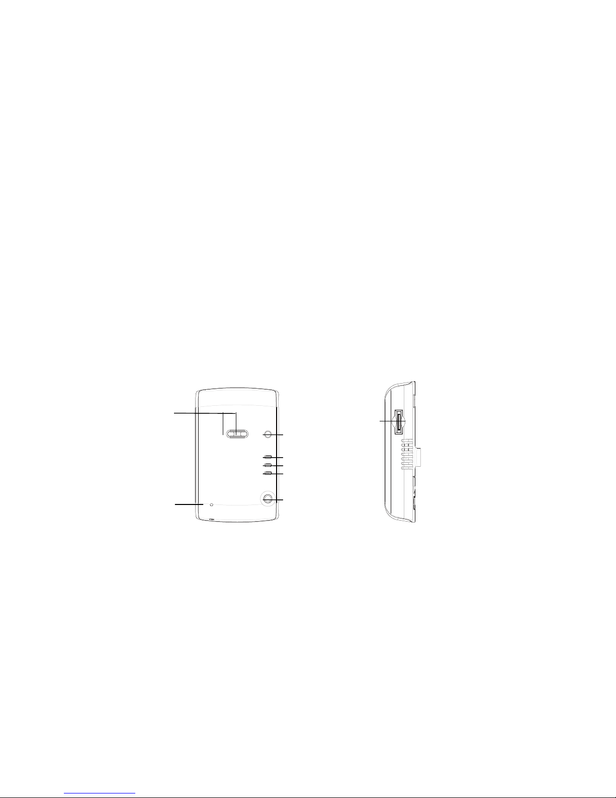
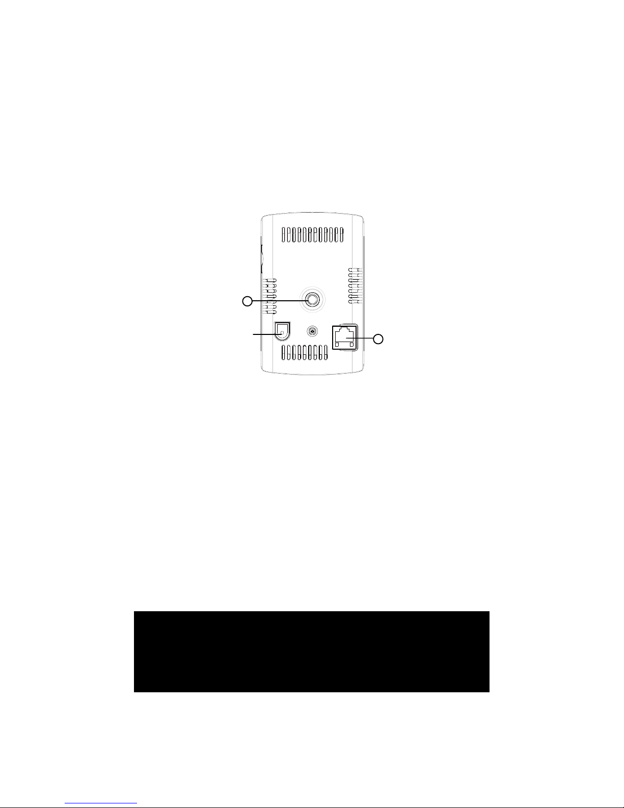
1.3. Understanding the camer a
1. Microphone – for receiving the audio. Effective distance is about 5 meters.
2. Lens – the lens is inside the camera body and the focus of the lens is fixed There are two
sensors for day and night use separately.
3. WPS button – this optional function is to automatically synchronize the wireless WiFi
connection to a WPS enabled WiFi router
4. Micro SD card indication LED (yellow) – this LED is to indicate the recording status of the
Micro-SD card. It will be constantly lit when the Micro-SD card is inserted and will blink
during recording.
5. Ethernet indication LED (blue) – this LED is to indicate if the Ethernet link is ok. When the
Page 6
6
Ethernet cable is connected between the router and camera, the LED will be lit. When data
is being transferred, the LED will blink.
6. Status indication LED (red) – this LED is to indicate the internet connection status. When
connected to the internet, the LED will be a constant red light. If there is any connection
problem, the LED will blink.
7. IR LED – Infra Red LED for night vision
8. Micro-SD card slot – for inserting the Mic ro-SD Card. (supports up to 32GB/ minimum 2GB)
9. Power jack – Connects to the 5V DC power supply adaptor
10. Bracket holder screw nut – Holds the bracket in place to the camera body. With the bracket,
you can place the camera on a flat surface, or mount on the wall/ceiling.
11. Ethernet jack – Connects to an RJ45 Ethernet cable. When connected to the internet via
the router, the blue LED with be lit on the camera
NEED HELP
Most issues can be solved over the phone. Call the customer helpline on
0844 736 9149 Monday to Friday 9.00am to 5.00pm
Calls charged at service providers national rate.
10
11
Page 7
7
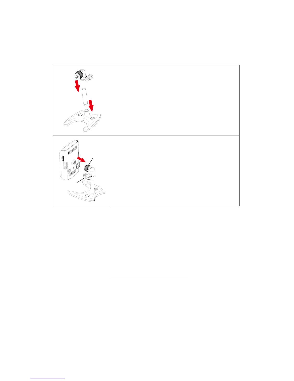
1.4. Quick installation and usage
Attach the bracket to the body
(1) Set up the bracket as indicated.
(2) Screw bracket holder nut of the camera onto the bracket.
Rotate the camera 3-4 times so that the camera is loosely
attached to the bracket. Adjust and “hold” the camera to a
desired angle and turn the swivel A to fasten the camera. Then
you can turn the upper part of the bracket (along with the
camera) to an appropriate direction. Lastly turn the swivel B to
fix the camera.
Viewing video from the camera
There are only three things that you need to do to view the video from the camera.
1. Connect the camera to your broadband router.
2. Log on to the web page “
https://GlobalGuard.Friedland.co.uk
3. Enter your GlobalGuard HomeID, Admin/User ID and password details on the web page
to login to your account so that the camera can be added
”.
Swivel (A)
Swivel (B)
Page 8
8
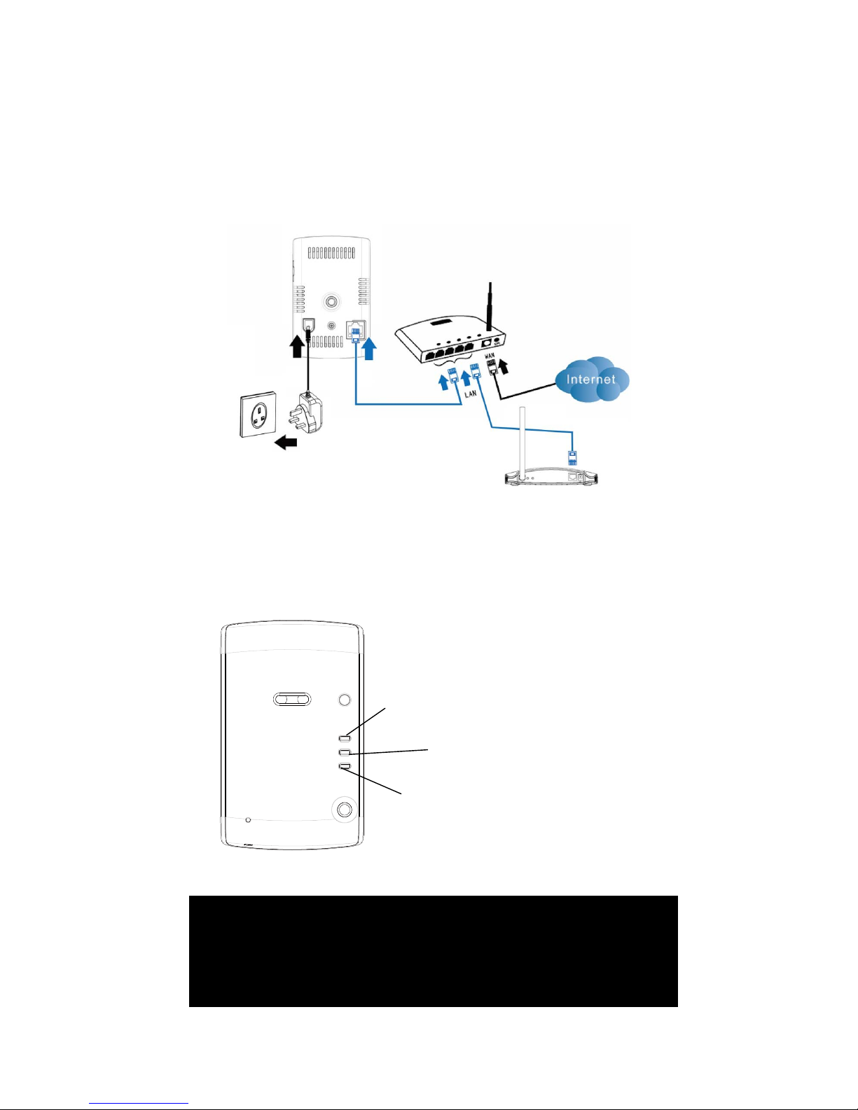
1) Connect the camera to your broadband router
Connect the camera as shown below in Figure 1-1.
Note: The IP camera must be connected to the same local network as the IP gateway to
ensure recording when trigger. Ideally both should be conne cted to the same router.
Figure 1-1: Connect Ethernet cable to a LAN port on your router.
The status LED should appear as a stable red light which indicates connected to the internet
(Figure 1-2).
Figure 1-2: Indication LEDs on the camera
Micro SD card indication
LED (Yellow)
Ethernet indication
LED (Blue)
Status indication LED
(Red)
NEED HELP
Most issues can be solved over the phone. Call the customer helpline on
0844 736 9149 Monday to Friday 9.00am to 5.00pm
Calls charged at service providers national rate.
Page 9

9
2) Log on to the web page “
https://GlobalGuard.Friedland.co.uk
”.
Enter your Home ID, Admin/User ID and password details to log into your account (Figure 1-3).
Figure 1-3: Log in the web page
After entering the web page, click on followed by “IP CAM Settings” to enter the “IP
CAM settings” page (Figure 1-4):
Figure 1-4: Click on the link to enter IP Cam settings
On the IP Cam Settings page, click on to add a new IP camera
Page 10

10
You will then be prompted to enter the MAC code for the camera you purchased.
IMPORTANT: Remember to follow the on screen instructions in the
online web software for registering the camera to operate with your
system correctly
Locate the MAC code on the rear of your camera and key into the webpage during registration.
Figure 1-7: Location of MAC code for your camera
You can assign further settings to the camera after it is added ( Fi gur e 1-8):
Camera Info: A camera number is automatically assigned to the camera
Assign Location: This item determines where the camera should be installed in your home
Note:
a) When a P IR movement detector or other type of detector is triggered, the
MAC: [ID]
NEED HELP
Most issues can be solved over the phone. Call the customer helpline on
0844 736 9149 Monday to Friday 9.00am to 5.00pm
Calls charged at service providers national rate.
Page 11

11
camera assigned to the SAME location will start recording. Therefore you
should plan beforehand and assign the location group to the correct
camera(s).
b) If the Location is set to ‘None’ this camera will record whenever ANY detector
is triggered.
Assign Camera Name: Enter a name for easy identification.
Enable Wifi Function : Set wireless Wifi feature ON/OFF
Audio: Set audio ON/OFF.
Figure 1-8: Advanced settings for the IP camera
3) View the image from the IP camera
After a camera is added to your system, the LED on the Gateway will also light up to indicate
that a new camera has been added to your system (Figure 1-9).
Figure 1-9: LED status on the Gateway
Click on to enter the camera view page. Select the camera added and click on
“View” to display live video. In this window, you can adjust the volume or stop the playing
(Figure 1-10 on next page).
Note: If the volume setting on your PC is set too high and the camera is located close to
it, then you may hear a loud whistling sound which is microphone feedback. Please
The 4 camera connection LEDs indicate the status of up to 8
cameras:
1. When connecting 1-4 cameras, LEDs 1-
4 will turn green
2. When the 5th camera is added, LED 1 will turn amber
(and so on).
3. If camera 1 is disconnected but camera 5 is still active,
LED 1 will turn red (and so on).
Page 12

12
reduce the PC speaker volume or move your PC further away from the Camera before
selecting “View”.
Figure 1-10: View the real-time image from IP camera
2. Wireless Connection Setup
2.1. Wireless connection (if your router has no WPS button)
Please read the following steps to setup the wireless connection with your router:
1. Have your router’s wireless network security information on hand using a PC
2. Enter the wireless security settings on the web configuration page.
3. Unplug the Ethernet cable.
1) Enter the wireless security settings on the web configuration page.
NEED HELP
Most issues can be solved over the phone. Call the customer helpline on
0844 736 9149 Monday to Friday 9.00am to 5.00pm
Calls charged at service providers national rate.
Page 13

13
First ensure that your broadband router is wireless (Wifi) enabled. Write down the wireless
security parameters, including the SSID, security type, encryption protocols and the “key”
values (refer to below for details). This information can also be obtained from the settings in
your PC or smartphone.
In order to use the wireless network, you need to fill in the following fields:
1. Wireless Network – this is the name of the wireless network of your wireless router (SSID)
2. Security type – You need to choose one of the followings: None, WEP, WPA/WPA2-PSK
3. WEP mode – when the WEP mode is chosen, you need also choose between 64-bit (5
char), 64-bit (10 hex), 128-bit (13 char) and 128-bit (26 hex) encryption mode, and then fill
the WEP key correctly.
4. WPA-PSK mode - when the WPA-PSK mode is chosen, you need also choose between
TKIP and AES encryption mode, and then fill the WPA-PSK key correctly. WPA2-PSK is
also supported. But WPA Enterprise or WPA2 Enterprise is not supported.
2) Enter the wireless settings on the web page.
Using your PC launch the Internet Explorer browser and go to
“
https://GlobalGuard.Friedland.co.uk
Note: The wireless network chosen for each camera must be on the same local network
as the IP gateway to ensure the IP Gateway is able to activate the video recording when
triggered.
”. Click on and then “IP CAM Settings” to
enter the camera settings page. Select the camera you added earlier from the “Camera Info”
item. Then enter a name for your camera (optional), enable the Wifi function, select the audio
feature to enable sound to be heard and enter the wireless settings information as requested on
the page. All the fields in this page must be filled correctly with the same settings the wireless
router. (Figure 2-1 on next page).
Page 14

14
Figure 2-1: Wireless settings for the IP camera
Click on “Apply” to save the changes. Wait approximately 1 minute to allow for the wireless
settings to save to the camera before proceeding to the next step.
3) Unplug the Ethernet cable
The wireless connection between the camera and router will begin when you unplug the
Ethernet cable connecting your camera and router (Figure 2-2).
Figure 2-2: Unplug the Ethernet cable to enable the wireless (WiFi) connection
The camera will detect the Ethernet cable unplugged and start the wireless connection. During
this period the LEDs on the camera will toggle. All the LEDs will turn off and the camera will
1 2 4 5 3
Page 15

15
restart. The wireless connection will be successfully established when the blue Ethernet LED
blinks and the Status LED remains red.
After the wireless connection is established, the camera will connect to the Internet
immediately.
If you need to relocate the camera in anoth er location of your home, first unplug the
power supply adaptor of the camera from the wall socket. Locate the camera to the
required location and power the adaptor on again. If locating much further away from
the wireless router, use a WiFi enabled laptop or your Smartphone’s display to check
the signal strength of the wireless (WiFi ) connection in that location. Check the video
from the live view web page can also be seen as a test. If wall/ceiling mounting, ensure a
power socket is located near the camera’s power adaptor.
Note: If you want to switch back to the wired Ethernet connecti on, jus t plu g in the Ether net
cable into camera again. Also it may be that if the wireless connection between the camera and
router is poor due to obstructions in your hom e, you ma y require a wired conn ecti on, i.e a
longer Ethernet cable than the one supplied
2.2. Wireless connection (if your router has a WPS button)
If your router or has a WPS button, then there are only three simple steps that you need to do to
establish a wireless connection with your router:
Note: If this function does not automatically work with the WPS function on your router
then follow the above process 2.1
1. Unplug the Ethernet cable from the camera.
2. Press and release the WPS button on the router. Press and release the WPS button on the
camera within one minute.
3. The yellow/blue/red leds on the camera will begin toggling. The toggling should stop within
one minute and the b lue led should turn on to indicate a wireless connection is established.
Page 16

16
3. Hardware Installation on wall/ceiling
(1) Use the bracket as a template to mark the position of fixing holes on the wall/ceiling. (Figure
3-1a & 3-1b)
Figure 3-1a
Figure 3-1b
(2) Drill the holes using a 5mm drill and mount the bracket using the supplied wall plugs and
screws. Alternatively use other suitable fixings for plasterboard walls/ceilings if required.
(Figure 3-2a & 3-2b)
Figure 3-2a
Figure 3-2b
(3) Mount the main body of camera onto the bracket. (Figure 3-3a & 3-3b)
NEED HELP
Most issues can be solved over the phone. Call the customer helpline on
0844 736 9149 Monday to Friday 9.00am to 5.00pm
Calls charged at service providers national rate.
Page 17

17
Figure 3-3a
Figure 3-3b
(4) Adjust the angle of the camera and then fasten the body. (Figure 3-4a & 3-4b)
Figure 3-4a
Figure 3-4b
(5) Connect the power adapter to the camera and power on the camera again. (Figure 3-5a &
3-5b)
Figure 3-5a
Figure 3-5b
(6) Vi ew the live video on the web page. Re-adjust the angle of the camera if necessary.
Power
Socket
Power
Adapter
Power
Socket
Power
Adapter
Page 18

18
4. Operation
4.1. How to view the camera live
(1) On your PC, launch the browser and go to “https://GlobalGuard.Friedland.co.uk
(2) On the login page, enter your HomeID, Admin/User ID and Password followed by the
verification code. Now click on the “Login” button.
”
(3) Click on to enter the camera view page.
(4) Select the camera and click on “View” to display the live video. On the right side panel you
can adjust the volume or stop the playing.
Note: The Android/Apple IOS mobile “GlobalGuard” App can also now be used to view
any cameras connected to your system. If not already done download and install this
App from the marketplace or App store and use your GlobalGuard online account login
details to sign in.
Page 19

19
4.2. How does the camera record to the SD card
a) Manually recording video clips:
(1) After logging in to the web page, click on to enter the camera view page.
(2) Click on the “REC” button to start a recording for a period of approximately 30 seconds.
b) When a security detector is triggered:
(1) After a door/window contact detector or another type of security detector is triggered whilst
your alarm system is armed, your IP gateway will locate the corresponding IP camera in
that location and inform it to begin recording.
(2) The camera will start to record approximately 30 second video clips on to the SD card
Note: When a PIR movement detector or any type of security detector is triggered, only
the IP camera assigned to the SAME location as the d etector will start recording. If a
camera’s Location is set to ‘None’, it will record whenever ANY detector is triggered.
Note also all cameras will record when the control panel detects event conditions of
Panic, Tamper, Fire & Duress regardless of any location it is set to.
The Android/Apple IOS mobile “Globa lGuard ” App can be us ed to re cord video file s and
save to the SD card in the camera. First download and install this App from the
Marketplace or App store and use your onl ine account login details to sign in.
Page 20

20
4.3. How to playback video files from the web
(1) After logging in to your account on the web page, click on to enter the video
playback page.
(2) Select a connected camera, and then click on the (refresh) icon to refresh the
playback list.
(3) Click on a desired filename (sorted by date and time) to view the playback. On the right side
panel you can adjust the volume or stop the playback
Video file name format:
Example above means video file recrded on:
27
th
DEC 2011 at 15:32:40 (or 3:32pm and 40 seconds)
(A) Yea r
(B) Month
(C) Day
(D) Hour
(E) Minute
(F) Second
(G) The last 3 zeros are affixed to
the file name.
Page 21

21
4.4. Backing up video files from the micr o S D card on PC
(1) Remove the micro SD card from the camera.
(2) Insert the micro SD card into a suitable SD card reader for your PC. Some PC’s have a
built-in card reader. In that case you can simply insert the micro SD card into the built-in
card reader.
Note: Use the suitable SD card adapter if your PC can not read micro SD cards directly.
(3) After your PC detects the storage device, copy the folder containing the video files onto
your PC where required
(4) After the copy is complete, disconnect the adaptor from your PC and then remove the micro
SD card.
(5) Insert the micro SD card back into the camera.
(6) Power off wait a few seconds and then power on the camera to ensure that the camera can
reboot its functionality correctly.
4.5. GlobalGuard CamPlay software
Playing back video files stored on your PC
If video files are stored on your PC possible for evidence or backup purposes, then the files can
be played back on the PC using the ‘GlobalGuard_CamPlay’ software.
(1) Download this software and the GlobalGuard software manual by visiting
“
www.GlobalGuard.Friedland.co.uk”
(2) Install and open the player
(3) Refer to section [GlobalGuard Camplay software] in the GlobalGuard software manual for
details on using it.
Note: Not all features of this software are applicable for the GlobalGuard Camera
NEED HELP
Most issues can be solved over the phone. Call the customer helpline on
0844 736 9149 Monday to Friday 9.00am to 5.00pm
Calls charged at service providers national rate.
Page 22

22
5. Specifications
Power supply
5V DC, 1A
Network interface
Ethernet 10BaseT/100BaseTX, Auto-MDIX, RJ-45
Wireless interface
IEEE 802.11n 90 - 150 Mb ps
IEEE 802.11g 6 - 54 Mbps
IEEE 802.11b 1 - 11 Mbps
Transmit power: 14.5dBm typically @ 802.11g
17.5dBm typically @ 802.11b
Receiver sensitivity: 54Mbps: Typical -73dBm @ 10% PER
11Mbps: Typical -86dBm @ 10% PER
Antenna gain: 0.01 dBi
Open field RF operating
range
Approximately 100m
Image sensor
RGB VGA 1/4 inch CMOS
Day and night separate sensors
Automatic exposure control, automatic white balance, automatic
gain control, automatic brightness control.
Light sensitivity
0.2 Lux ( IR LED off )
0 Lux (with 10 meters IR LED on)
Automatically turn on the IR LED on low light environment.
Lens / viewing angle
3.2 mm, F2.0, viewing angle: 60.3°, fixed iris.
Day and night separate lens
Night vision range
Up to 10m
Buttons
WPS button for optional automatic wireless (WiFi) setup for WPS
enable routers only
Indicators
Blue LED for Internet connection status indication
Red LED for Ethernet connection indication
Yellow LED for micro SD card recording indication
Video compression
H.264, baseline profile level 3.1
Resolution
VGA(640x480) ; QVGA(320x240)
Audio
Built-in microphone for audio monitoring
Page 23

23
Micro SD Card for
recording
Minimum 2GB / Maximum 32GB
2GB stores approximately 300 x 33 second video files
3 seconds pre-recording
Operating conditions
0-50 °C
Humidity 20 – 80% RH (non-condensing)
Mounting conditions
Dry indoor use only
Appendix A. Performance Information
1. Video Performance Information
The video quality is dependent on the speed of your internet connection (i.e, upload/download
speed). For better video quality, you need to know and increase if necessary the internet
connect speed (bandwidth). If the internet connection speed (bandwidth) is low, the video
quality could be poor. In some worst cases, the video displayed could be disconnected. In order
to acheive the best video quality, your ISP (internet service provider) should provide no less
than 512kbps upload speed. Note that upload speed is different from download speed.
Also note that when multiple users are viewing video from the same camera simultaneously,
the basic video bandwidth (512kbps) multiplied b y the number of users will be the
recommended total bandwidth required for the Internet upload speed to display good video
quality.
2. Wireless (WiFi) Performance Information
The wireless connection performance is dependent on the following factors
• Distance between the camera and your wireless router
• The number of devices connected to the router.
• Obstructions between the camera and router such as walls
In general case, if there are no obstructions between the camera and the router, the open field
operating range is approximately 100m.
Page 24

24
Appendix B. Trouble shooting
How many IP cameras can I add?
You can connect up to 8 x IP cameras to the
system.
What’s going on when the red led
light on the camera is flashing?
When the camera is connected to the Internet and
working correctly, the red led light will be on
constantly. If the red led light is flashing, it’s
probably because there is a connection problem.
Please check the internet connection again
When the camera is connected to the
router through wireless connection,
the video quality is not good, how
could I fix this problem?
When the camera is connected wirelessly and the
video quality is poor, it’s probably because the
camera is located too far from the router or that
there are are too many devices connected to the
router
I can view the video remotely, but the
video quality is not good and
sometimes the video disconnects and
reconnects again by itself.
It’s probably because the internet bandwidth
(internet connection speed) is not big enough.
Consider upgrading for a better internet connection
from your IPS (internet service provider). The
camera requires a minimum 512kbps upload speed
for viewing the video smoothly.
Loud whistling sound heard on my
PC from the Camera
The camera may be located too close to your PC.
Please reduce the speaker volume on your PC or
the volume of the camera
NEED HELP
Most issues can be solved over the phone. Call the customer helpline on
0844 736 9149 Monday to Friday 9.00am to 5.00pm
Calls charged at service providers national rate.
Page 25

25
Disposal and Recycling (Directive 2002/96/EC)
The product is classif ied b y the Waste Elec trica l or E lect ronic Equ ipm ent (W EEE) Directi ve. It
should not be disposed of with other household or ot her commercial waste. At the end of its
useful life the packaging and product should be disposed of via a suitable recycling centre. For
information on available facilities, please contact your local authority or retailer from where the
product was purchased.
WEEE bin logo here
Notes
Camera 1 MAC ID:
Location:
Camera 2 MAC ID: Location:
Camera 3 MAC ID: Location:
Camera 4 MAC ID: Location:
Camera 5 MAC ID:
Location:
Camera 6 MAC ID:
Location:
Camera 7 MAC ID:
Location:
Camera 8 MAC ID: Location:
Page 26

26
Disposal and Recycling (Directive 2002/96/EC)
The product is classif ied b y the Waste Elec trica l or E lect ronic Equ ipm ent (W EEE) Directi ve. It
should not be disposed of with other household or ot her commercial waste. At the end of its
useful life the packaging and product should be disposed of via a suitable recycling centre. For
information on available facilities, please contact your local authority or retailer from where the
product was purchased.
Guarantee
Novar ED&S undertakes to replace or repair at its discretion goods (excluding non
rechargeable batteries ) sho uld the y bec om e defec tive with in 1 year so lel y as a res ult of f ault y
materials and workmanship.
Understandably if the pro duct has not been installed, operat ed or maintained in accordance
with the instructions, has not been used appropriately or if any attempt has been made to rectify,
dismantle or alter the product in any way the guarantee will be invalidated.
The guarantee states Novar ED&S entire liability. It does not extent to cover consequential loss
or damage or installat ion cos ts arising f rom the def ective pr oduct. T his guarant ee does n ot in
any way affect the statutory or oth er rights of a consumer and applies to pro ducts installed
within UK and Eire only.
If an item develops a fault, the product must be returned to the point of sale with :
1. Proof of purchase.
2. A full description of the fault.
3. All relevant batteries (disconnected).
Novar Electrical Devices and Systems Limited (A Honeywell company)
The Arnold Centre, Paycocke Road, Basildon, Essex SS14 3EA. UK
www.friedlandproducts.com
© Novar Electrical Devices and Systems Limited. 2013
CE
50072730-001 Rev.B
CUSTOMER HELPLINE
Most issues can be solved over the phone. Call the customer helpline on
0844 736 9149 Monday to Friday 9.00am to 5.00pm
Calls charged at service providers national rate.
 Loading...