

Response CENTURION SCOUT Owner's Manual
Response Technologies, Ltd.
Centurion SCOUT Owner’s Manual v2
PREVENT INJURIES, DAMAGE or a SECURITY BREACH.
Read, understand, and follow this manual.
Response Technologies, Ltd.
CENTURION SCOUT OWNER’S MANUAL

Response Technologies, Ltd.
Centurion SCOUT Owner’s Manual v2
TABLE OF CONTENTS
SECTION 1: SAFETY INSTRUCTION .........................................................................................1
SECTION 2: SYSTEM OVERVIEW .............................................................................................3
FRONT PANEL OVERVIEW .....................................................................................................3
EXTERNAL CABLE PORTS ......................................................................................................4
SECTION 3: SYSTEM OPERATIONS ..........................................................................................5
INTERNAL BATTERY CHARGING .........................................................................................5
SYSTEM POWER UP ..................................................................................................................5
SYSTEM DEPLOYMENT ...........................................................................................................6
SECTION 4: SYSTEM CONFIGURATION ..................................................................................7
ENTRY/EXIT DELAY ................................................................................................................7
RECORD MESSAGE ...................................................................................................................8
PLAY MESSAGE ........................................................................................................................8
SPEAKER ON/OFF......................................................................................................................8
LINK SENSOR .............................................................................................................................9
UNLINK SENSOR .......................................................................................................................9
RESET ALL SETTINGS ............................................................................................................11
INACTIVE-TIME SCHEDULER ..............................................................................................11
RELAY CONFIGURATION .....................................................................................................12
SECTION 5: CONSOLE CONFIGURATION .............................................................................13
CONNECT USING CONSOLE .................................................................................................13
HISTORY LOG ..........................................................................................................................14
SAVE/ARM ................................................................................................................................15
RESET DEFAULT CONFIGURATION ...................................................................................15
DATE/TIME ...............................................................................................................................15
INACTIVE-TIME SCHEDULER ..............................................................................................15
AUDIO OUTPUT .......................................................................................................................16
SYSTEM CONFIGURATION ...................................................................................................17
RADIO CONFIGURATION ......................................................................................................18
SECTION 6: SUPPORT INFORMATION ...................................................................................19
TROUBLESHOOTING FAQ .....................................................................................................19
WARRANTY .............................................................................................................................21
PAIRED/UNPAIRED ..............................................................................................10
CONFIGURATION .................................................................................................16
www.response-technologies.com i ©Response Technologies, Ltd.
Revised: January 9, 2015

Response Technologies, Ltd.
Centurion SCOUT Owner’s Manual v2
FOREWORD
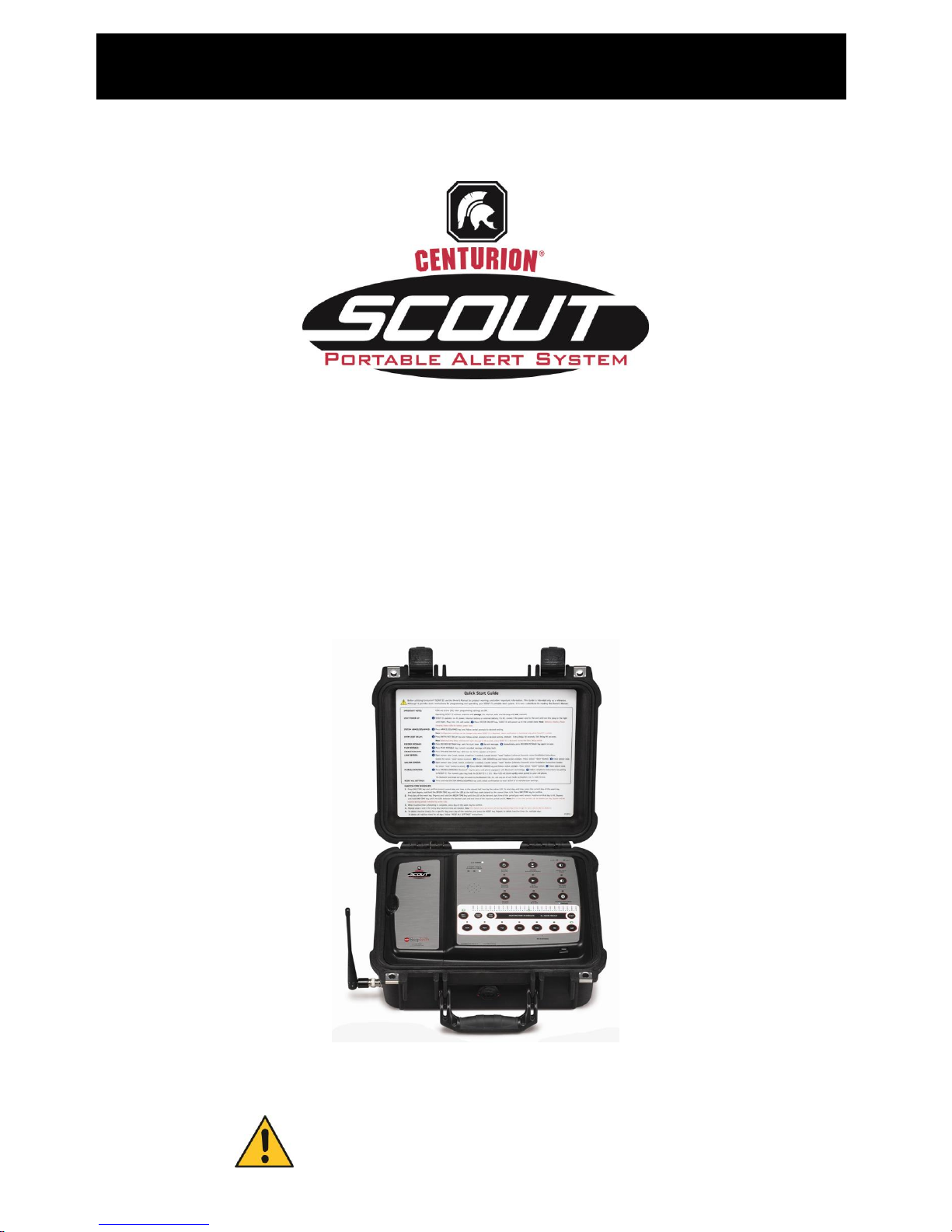
We would like to thank you for purchasing the Centurion SCOUT Portable Alert System from
Response Technologies, Ltd.. The SCOUT is a wireless communication security system
designed for portable covert operations with the capability to transmit a user-recorded message
to security personnel by way of two-way radio, Bluetooth enabled phone, built in speaker, or
relay activated external device. The speed and substance of the transmitted message help security
personnel know instantly where assistance is needed, as well as important facts about the
location. A variety of sensors, such as motion detectors (PIR), duress buttons, door/window
contacts, smoke alarms, and others may be used with the SCOUT.
The SCOUT utilizes leading-edge technology and is manufactured to the highest standards of
quality and excellence. The following Owner’s Manual is intended as a detailed guide for
operating the SCOUT. Please reference the Quick Start Guide located in the lid of the SCOUT
for everyday normal operations.
Should you have any questions, please call 513 202 5500 or email info@response-
technologies.com. We look forward to working with you for many years to come.
www.response-technologies.com ii ©Response Technologies, Ltd.
Revised: January 9, 2015

m Version 2.00A
Section 1
Safety Instructions
User Manual
Always read and follow safety messages!
Your safety and the safety of others is very important. We have provided several important
safety messages in this owner’s manual. A safety message alerts you to a potential hazard and
instructs you on how to avoid or reduce the risk. Each safety message is preceded by a safety
alert symbol . Please carefully read and follow these important messages.
SAFETY INSTRUCTIONS
Reduce the risk of PERSONAL INJURY or PROPERTY DAMAGE:
READ and UNDERSTAND ALL INSTRUCTIONS before installing or operating the
Centurion SCOUT Portable Alert System.
Do not attempt to service the SCOUT yourself unless you are an AUTHORIZED
CENTURION SCOUT TECHNICIAN. Always follow installation instructions closely.
Install the SCOUT near an electrical (AC) outlet. The AC power cord is your SCOUT’s
main AC disconnecting device and must be easily accessible at all times. For your
safety, the power cord provided with your system has a grounded plug. Always use the
power cord with a properly grounded wall outlet to avoid the risk of electrical shock.
AVOID ELECTRIC SHOCK. Disconnect all power sources by unplugging the unit and
removing its internal battery before attempting any maintenance or service. Always
follow safe work practices to control hazardous electrical energy. Do not connect or
disconnect any cables or perform maintenance or reconfiguration of the SCOUT during
an electrical storm.
Do not dispose of the SCOUT’s battery in a fire or with normal waste. Battery cells may
explode. Discard a used battery according to the manufacture’s instructions or contact
your local waste disposal agency for disposal instructions. Dispose of a spent or
damaged battery promptly.
Operating SCOUT without antenna will damage the internal radio and message will not
transmit.
www.response-technologies.com - 1 - ©Response Technologies, Ltd.
Revised: January 9, 2015

m Version 2.00A
Section 1
Safety Instructions
User Manual
SAFETY INSTRUCTIONS
Keep your Centurion SCOUT Portable Alert System OPERATING PROPERLY:
Visually inspect the SCOUT on a daily basis. Check the front panel to ensure correct
LED lights are lit.
If the system is not ARMED, alarms WILL NOT BE PROCESSED or LOGGED.
SYSTEM ARM/DISARMED LED will be lit when the system is armed. Sensors
activated while the unit is disarmed will not transmit alarms via the radio system or
other communication interface option.
The ALARM HISTORY LOG is where important system activities are recorded, such as
sensor missing and low battery notifications. These notifications are NOT transmitted
via radio system or other communication interface options. The log can be viewed, saved
to disk, or printed using the provided client software.
PERIODICALLY TEST your Centurion SCOUT Portable Alert System by activating
sensors to confirm alert is being broadcast. Immediately investigate and correct any
issues, including sensors that fail to respond properly. Contact an authorized SCOUT
technician for help with troubleshooting.
Testing should ALWAYS be performed:
after the initial configuration of the system,
after any changes to the system’s configuration are made, and
as often as prescribed by your agency’s Standard Operating Procedures (SOP).
When in use in the field (deployed) or being stored, always keep the SCOUT unit in a
secure location to prevent tampering.
The site should be free of excessive electrostatic presence, extreme temperatures
(above 150 degrees / below -20 degrees Fahrenheit) and high moisture content. These
conditions could damage sensitive electronic components.
Operate with care, SCOUT can be operated with the lid open or closed.
The real-time clock is serviced by the internal battery. Allowing the internal battery to
drain will affect the accuracy of the real-time clock.
Store the unit plugged into an AC power source in order to maintain a full charge on the
internal battery. Internal battery will drain over a long period of time in storage.
www.response-technologies.com - 2 - ©Response Technologies, Ltd.
Revised: January 9, 2015
Section 2
System Overview
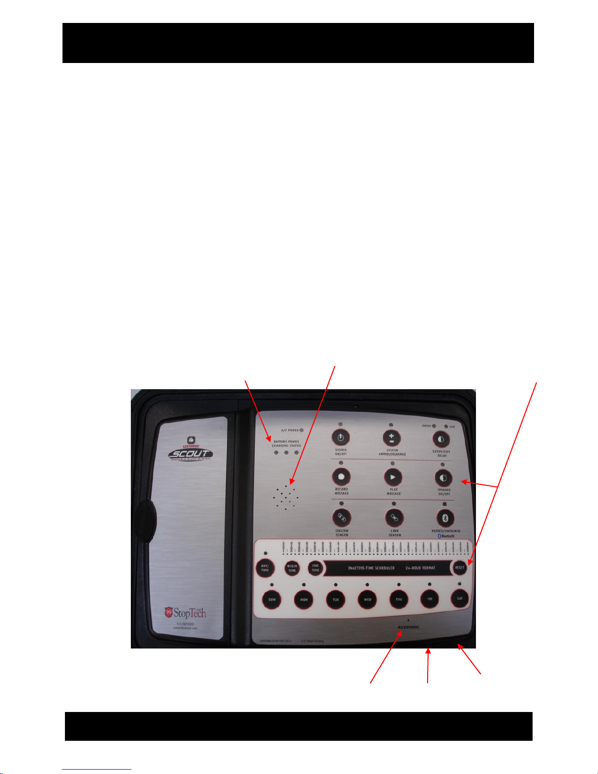
Reset Button
USB Port
Microphone
Speaker
Battery Status
LED Lights
Touch Key
Interface
SYSTEM OVERVIEW
FRONT PANEL OVERVIEW
Touch key interface with LED lights.
Battery status indicating LED lights.
Built-in microphone for recording verbal message.
Built-in speaker for listening to verbal message.
USB Port connector for USB communication to PC.
Recessed pinhole reset button for performing a hard reset.
www.response-technologies.com - 3 - ©Response Technologies, Ltd.
Revised: January 9, 2015
Section 2
System Overview
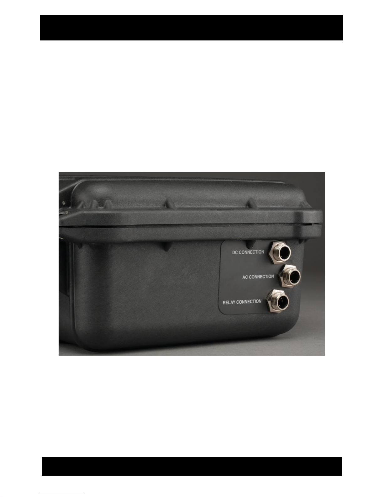
EXTERNAL CABLE PORTS
AC Receptacle outlet to connect AC power cord.
DC Connector outlet to connect DC power adapter.
Two-Way Relay Connector allows the system to activate an external device, and/or to
have an external device activate the system using an N/O or N/C contact.
www.response-technologies.com - 4 - ©Response Technologies, Ltd.
Revised: January 9, 2015

Section 3
System Operations
R
R
R
E
E
E
D
D
D
L
L
L
E
E
E
D
D
D
1
1
1
–
–
–
3
3
3
3
3
3
%
%
%
b
b
b
a
a
a
t
t
t
t
t
t
e
e
e
r
r
r
y
y
y
p
p
p
o
o
o
w
w
w
e
e
e
r
r
r
l
l
l
e
e
e
v
v
v
e
e
e
l
l
l
Y
Y
Y
E
E
E
L
L
L
L
L
L
O
O
O
W
W
W
L
L
L
E
E
E
D
D
D
3
3
3
4
4
4
–
–
–
6
6
6
6
6
6
%
%
%
b
b
b
a
a
a
t
t
t
t
t
t
e
e
e
r
r
r
y
y
y
p
p
p
o
o
o
w
w
w
e
e
e
r
r
r
l
l
l
e
e
e
v
v
v
e
e
e
l
l
l
G
G
G
R
R
R
E
E
E
E
E
E
N
N
N
L
L
L
E
E
E
D
D
D
6
6
6
7
7
7
–
–
–
9
9
9
9
9
9
%
%
%
b
b
b
a
a
a
t
t
t
t
t
t
e
e
e
r
r
r
y
y
y
p
p
p
o
o
o
w
w
w
e
e
e
r
r
r
l
l
l
e
e
e
v
v
v
e
e
e
l
l
l
SYSTEM OPERATIONS
INTERNAL BATTERY CHARGING
The system maintains a trickle charge on the internal back-up battery while system is connected
to an AC power source using the provided AC power cable.
Battery charging status is indicated by the blinking LED located under BATTERY POWER
CHARGING STATUS.
When system is turned OFF and charging, a solid green LED indicates a full charge.
Note: Store the unit plugged into an AC power source in order to maintain a full charge on
the internal battery. Internal battery will drain over a long period of time in storage.
SYSTEM POWER UP
AC Operation
For AC, connect the power cord to the unit and turn the plug collar to the right until tight
(reference page 4 – External Cable Ports). Plug into 110 volt outlet. A/C POWER LED will be
lit when line power applied.
Press the SYSTEM ON/OFF key. System ON is indicated by the SYSTEM ON/OFF LED being
lit.
The SCOUT will power up in the armed state. The unit is armed and ready to process alarms
when the SYSTEM ARMED/DISARMED LED is lit.
Note: Reference Battery Power Charging Status LEDs for battery power level.
www.response-technologies.com - 5 - ©Response Technologies, Ltd.
Revised: January 9, 2015
 Loading...