

RESPEKTA CH 21060SB, CH 21060WB, CH 24060 SAM, CH 24060 WAM, CH 24090 SAM Assembly instructions
...Page 1
D
Montageanleitung
Kopffreie Dunstabzugshauben
Mod. No.:
CH 21060SB
GB
Installation Instructions
CH 21060WB
Inclined Cooker hoods CH 24060 SAM
CH 24060 WAM
CH 24090 SAM
CH 24090 WAM
CH 88060 S A+
CH 88060 W A+
CH 88090 S A+
CH 88090 W A+
CH 33060 S B
CH 33060 W B
fi90920tnmNEG
NEG-Novex Großhandelsgesellschaft für Elektro- und Haustechnik GmbH, Chenover Str. 5, D-67117 Limburgerhof
Page 2
Deutsch Montageanleitung Dunstabzugshauben
D
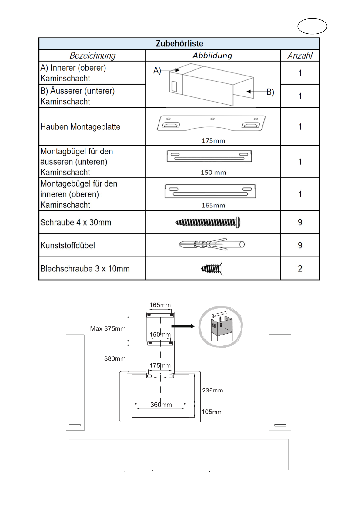
Gesamt Montage Übersicht:
Abstand zum Kochfeld: Siehe Kapitel 11.1 der Bedienungsanleitung
Achtung!
Die in der Abbildung angegebenen Abmessungen variieren von Modell zu Modell. Bitte
die Angaben auf der Bohrschablone für Ihr Gerät beachten.
fi190920TNM 1/4
Page 3
Inhaltsverzeichnis:
Montage der Ventilklappen 2
Seite
Montage der Haube für
Umluftbetrieb
Montage der Haube für
Abluftbetrieb
2 - 3
4
Stellen Sie vorerst die Stromzufuhr sicher. Diese muss von einer Fachperson eingerichtet werden.
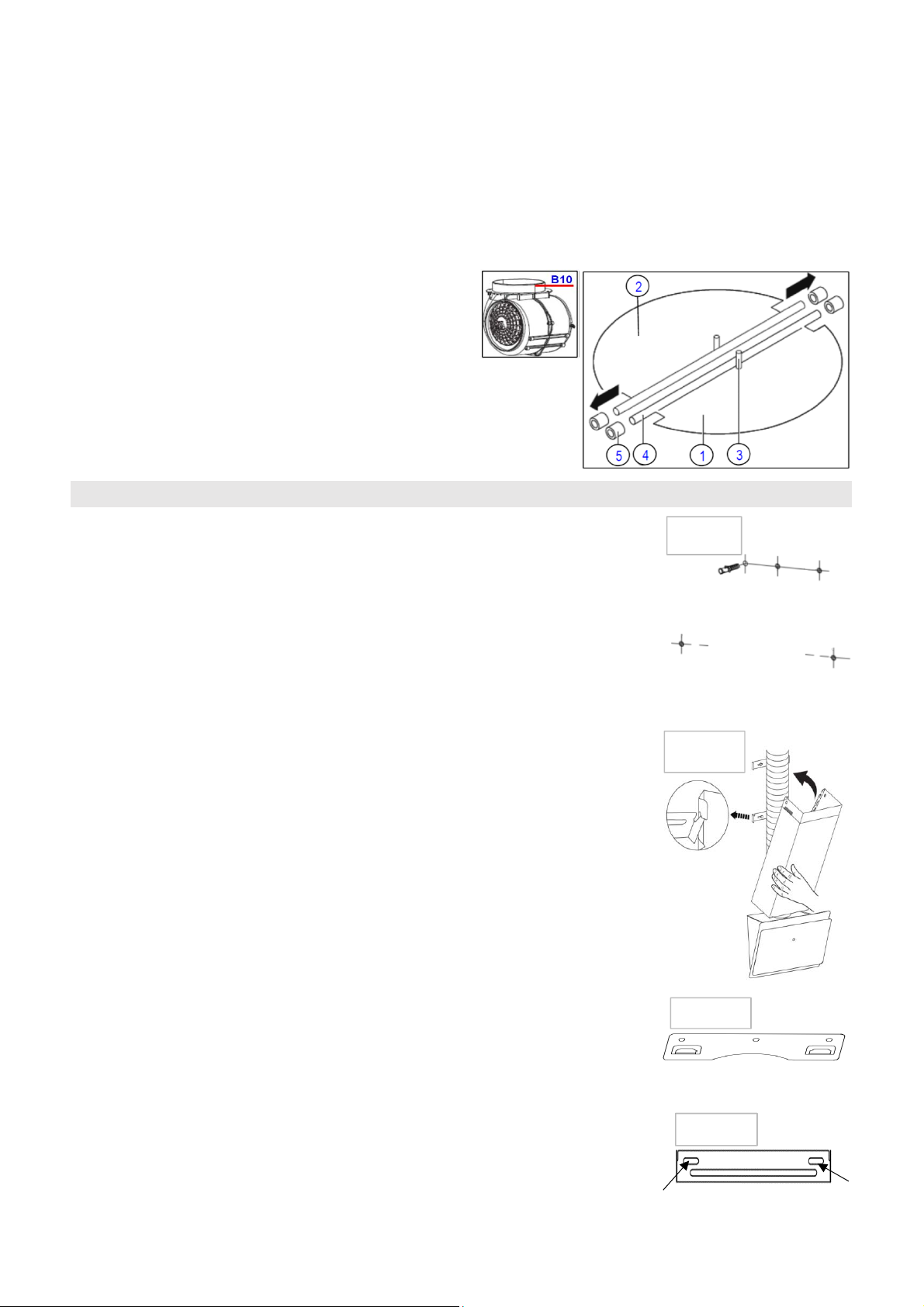
Achtung! Vor der Montage der Haube die Ventilklappen wie nachstehend beschrieben einsetzen:
Montage der Ventilklappen:
Falls die Ventilklappen nicht werkseitig montiert sind:
• Montieren Sie zuerst Halbteil 1 im Stutzen B10
• Stifte 3 müssen nach oben ausgerichtet sein;
• Die Achse 4 in die Löcher 5 am Stutzen B10 einführen;
• Wiederholen Sie alle Vorgänge für die Montage des Halbteils 2
Montage der Haube für Umluftbetrieb:
1. Ziehen Sie an der Wand mit Bleistift eine waagrechte Linie auf der Höhe an
welcher die Hauben Montageplatte montiert werden soll. (Dazu am besten eine
Wasserwage verwenden)
Abb. a)
2. Halten Sie die Oberkante der Hauben Montahgeplatte 1 (Abb.e) an die mit Bleistift
gezogene Linie und markieren Sie die 3 Bohrlöcher mit Bleistift.
3. Bohren Sie mit einem 8mm Steinbohrer bei den 3 Bleistiftmarkierungen je ein
30mm tiefes Loch in die Wand. Prüfen Sie zur Sicherheit den Durchmesser der Dübel
mit einer Schieblehre.
4. Halten Sie die mitgelieferte Bohrschablone so an die Wand, dass die 3 Bohrlöcher
für die Hauben Montageplatte mit denen auf der Bohrschablone übereinstimmen und
markieren Sie die 2 unteren Bohrlöcher für die Hauben Sicherung auf der
Bohrschablone mit einem Bleistift.
5. Bohren Sie mit einem 8mm Steinbohrer bei den 2 Bleistiftmarkierungen je ein
30mm tiefes Loch für die Hauben Sicherung in die Wand.
6. Setzen Sie je einen Dübel in die 5 gemachten Bohrlöcher (Abb. a).
7. Befestigen Sie die Hauben Montageplatte an der Wand.
8. Hängen Sie die Haube an die Hauben Montageplatte. (Abb. c)
9. Klinken Sie den Montagebügel für dem äusseren (unterer) Kaminschacht oben am
äusseren (unteren) Kaminschacht ein. (Abb. b)
10. Setzen Sie den äusseren (unteren) Kaminschacht auf die Haube und markieren
Sie die 2 Bohrlöcher (Abb. d) durch die Bohrungen des oben eingeklinkten
Montagebügels an der Wand.
Abb. b)
Abb. c)
11. Entfernen Sie den äusseren Kaminschacht wieder von der Haube.
12. Klinken Sie den Montagebügel oben am entfernten Kaminschacht aus.
13. Bohren Sie nun mit einem 8mm Steinbohrer je ein 30mm tiefes Loch in die 2 an
der Wand markierten Bohrlöcher für den Montagebügel (Abb. d).
fi190920TNM 2/4
Abb. d)
Page 4

14. Setzen Sie 2 Dübel in die gemachten Bohrlöcher.
15. Befestigen Sie den Montagebügel mit zwei 30mm Schrauben an der Wand.
16. Schieben Sie den inneren (oberen) Kaminschacht ganz in den äusseren (unteren)
Kaminschacht.
17. Setzen Sie die ineinandergeschobenen Kaminschächte auf die Haube und klinken
Sie diese am Montagebügel 2 (Abb. e). ein
18. Ziehen Sie den inneren Kaminschacht geradlinig bis oben an die Decke aus uns
drücken ihn fest an die Wand.
19. Ziehen Sie einen kurzen Markierungsstrich ganz oben an der Wand, auf beiden
Seiten des inneren Kaminschachtes. (Abb. f)
20. Schieben Sie den inneren Kaminschacht etwas nach unten.
21. Halten Sie den Montagebügel 3 (Abb. e) für den inneren Kaminschacht mittig
zwischen den Markierungsstrichen, ganz oben an die Decke und markieren sie die 2
Bohrlöcher durch die Bohrungen im Montagebügel.
22. Entfernen sie den Montagebügel wieder und bohren Sie nun mit einem 8mm
Steinbohrer je ein 30mm tiefes Loch in die 2 an der Wand markierten Bohrlöcher für
den Montagebügel.
23. Setzen Sie 2 Dübel in die gemachten Bohrlöcher und befestigen Sie den
Montagebügel 3 (Abb. e) mit zwei 30mm Schrauben.
Abb. e)
3
2
1
Abb. f)
Abb. g)
24. Ziehen Sie den inneren Kaminschacht ganz nach oben und befestigen Sie diesen
mit den zwei 10mm Blechschrauben seitlich am Montagebügel. (Abb. g)
25. Heben Sie die Hauben Front an, entfernen Sie den Fettfilter und befestigen Sie
die Haube mit zwei 30mm Schrauben durch die 2 Löcher in der Hauben Rückwand,
zur Sicherung der Haube. (Abb. h)
26. Montieren Sie die Kohlefilter seitlich am Motor. (Siehe Bedienungsanleitungs-
Kapitel "Einsatz der Kohlefilter"
Abb. h)
fi190920TNM 3/4
Page 5

Montage der Haube für Abluftbetrieb:
Achtung! Unbedingt das Kapitel 11. "Installation" der Bedienungsanleitung
beachten.
Die Mauerdurchführung muss für einen 150mm Abluftschlau bemessen sein.
(Bohrung ca. 155mm)
Für die Montage der Haube im Abluftbetrieb montieren Sie die diese wie unter
obigem Kapitel: "Montage der Haube für Umluftbetrieb:" beschrieben , jedoch ohne
Montage der Kohlefilter.
Gehen Sie bei der Montage wie folgt vor:
1. Entfernen Sie den äusseren und inneren Kaminschacht.
2. Montieren Sie den Abluftschlauch. (Abb. i)
3. Montieren Sie den äusseren und Inneren Kaminschacht wieder.
(a) (b)
Für die Endmontage der Haube im Abluft Betrieb
benötigen Sie einen Abluftschlauch für einen 150mm
Stutzen (a) und ein Abluftgitter (b) mit einen 150mm
Stutzen für den Anschluss des Abluftschlauchs. Diese
sind im Lieferumfang nicht enthalten.
Abb. i)
Abbildungen dienen z.T. nur zur Illustration
fi190920TNM 4/4
Page 6

English Installation Instructions for cooker hoods
GB
Total assembly overview:
Distance from the hob: See Chapter 11.1 of the user's manual
Attention!
The dimensions shown in the above illustration vary from model to model.
Please note the information on the drilling template for your appliance.
fi190920TNM 1/4
Page 7

Contents:
Installation of the valve flaps 2
Page
Installation of the hood for recirculating air mode
Installation of the hood for exhaust air mode
2 - 3
4
First ensure that the power supply is secure. This must be set up by a qualified specialist.
Caution! Before installing the hood, first install the valve flaps as described below:
Installation of the valve flaps:
If the valve flaps are not factory-fitted:
• First install semi-section 1 in nozzle B10
• Pins 3 must point upwards;
• Insert axis 4 in holes 5 on nozzle B10;
• Repeat all of these steps for installation of semi-section 2
Installation of the hood for recirculating air mode:
1. Using a pencil, draw a horizontal line on the wall at the height where the hood
mounting plate needs to installed. (this is best done using a spirit level)
Fig. a)
2. Hold the top edge of the hood mounting plate 1 (Fig. e) up against the pencil line
and mark the 3 drill holes with a pencil.
3. With an 8 mm masonry drill, make 30 mm holes in the wall at each of the 3 pencil
marks. To be on the safe side, check the diameter of the wall plugs with a slide
gauge.
4. Hold the drilling template supplied against the wall so that the 3 drill holes for the
hood mounting plate match those in the drilling template and mark the 2 lower drill
holes for securing the hood on the drilling template with a pencil.
5. With an 8 mm masonry drill, make a 30 mm hole at each of the 2 pencil marks to
secure the hood against the wall.
6. Insert a dowel into each of the 5 drill holes you have made (Fig. a).
7. Secure the hood mounting plate to the wall.
8. Hang the hood onto the hood mounting plate. (Fig. c)
9. Engage the top of the mounting bracket for the outer (lower) chimney shaft to the
inner (upper) chimney shaft. (Fig. b)
10. Set the outer (lower) chimney shaft on the hood and mark the 2 drill holes (Fig.
d) through the bores in the top mounting bracket hooked into the wall.
Fig. b)
Fig. c)
11. Remove the outer chimney shaft again from the hood.
12. Unhook the top mounting bracket from the removed chimney shaft.
13. With an 8 mm masonry drill, now make a 30 mm holes in each of the 2 drill
holes marked on the wall for the mounting bracket (Fig. d).
14. Install 2 wall plugs in the drill holes you have made.
15. Secure the mounting bracket to the wall using two 30 mm screws.
fi190920TNM 2/4
Fig. d)
Page 8

16. Slide the inner (upper) chimney shaft fully into the outer (lower) chimney shaft.
17. Place the interlinked chimney shafts onto the hood and hook this structure onto
mounting bracket 2 (Fig. e).
18. Full the inner chimney shaft straight upwards to the ceiling and press it firmly
against the wall.
19. Mark out a short line right at the top of the wall, on both sides of the inner
chimney shaft. (Fig. f)
20. Slide the inner chimney shaft slightly downwards.
21. Hold mounting bracket 3 (Fig. e) for the inner (upper) chimney shaft centrally
between the pencil marks right up against the ceiling and mark the 2 drill holes
through the bores in the mounting bracket.
22. Remove the mounting bracket again and then use an 8 mm masonry drill to
make 30 mm holes in the 2 drill holes marked on the wall for the mounting bracket.
23. Insert 2 wall plugs in the drill holes you have made, then secure mounting
bracket 3 (Fig. e) with two 30 mm screws.
Fig. e)
3
2
1
Fig. f)
Fig. g)
24. Pull the inner chimney shaft right up and secure it using the two 10 mm self-
tapping screws in the side of the mounting bracket. (Fig. g)
25. Lift up the front section of the hood, remove the grease filter and secure the
hood using two 30 mm screws through the 2 holes in the back of the hood. (Fig. h)
26. Fit the carbon filter to the side of the motor. (see User's Manual chapter
"Installation of the carbon filter"
Fig. h)
fi190920TNM 3/4
Page 9

Installation of the hood for exhaust air mode:
Caution! Always pay attention to Chapter 11. "Installation" in the User's manual.
The aperture in the wall must be able to accommodate a fume extraction hose
with a diameter of 150 mm. (bore approx. 155 mm)
To install the hood in recirculating air mode, please proceed as described in the
above Chapter: "Installation of hood for recirculating air mode:", but without
installing the carbon filter.
For installation, please proceed as follows:
1. Remove the outer and inner chimney shaft.
2. Install the air exhaust hose. (Fig. i)
3. Reinstall the outer and inner chimney shaft.
(a) (b)
Some of the pictures are for illustration only
For final installation of the hood in recirculating air mode,
you need an air exhaust hose for an exhaust nozzle with a
diameter of 150 mm (a) and an outer air exhaust grid(b)
with a 50 mm nozzle, for connecting up the air exhaust
hose. These are not included in the scope of delivery.
Fig. i)
fi190920TNM 4/4
 Loading...