

Page 1
Programming guide
H-2000-6411-00-A
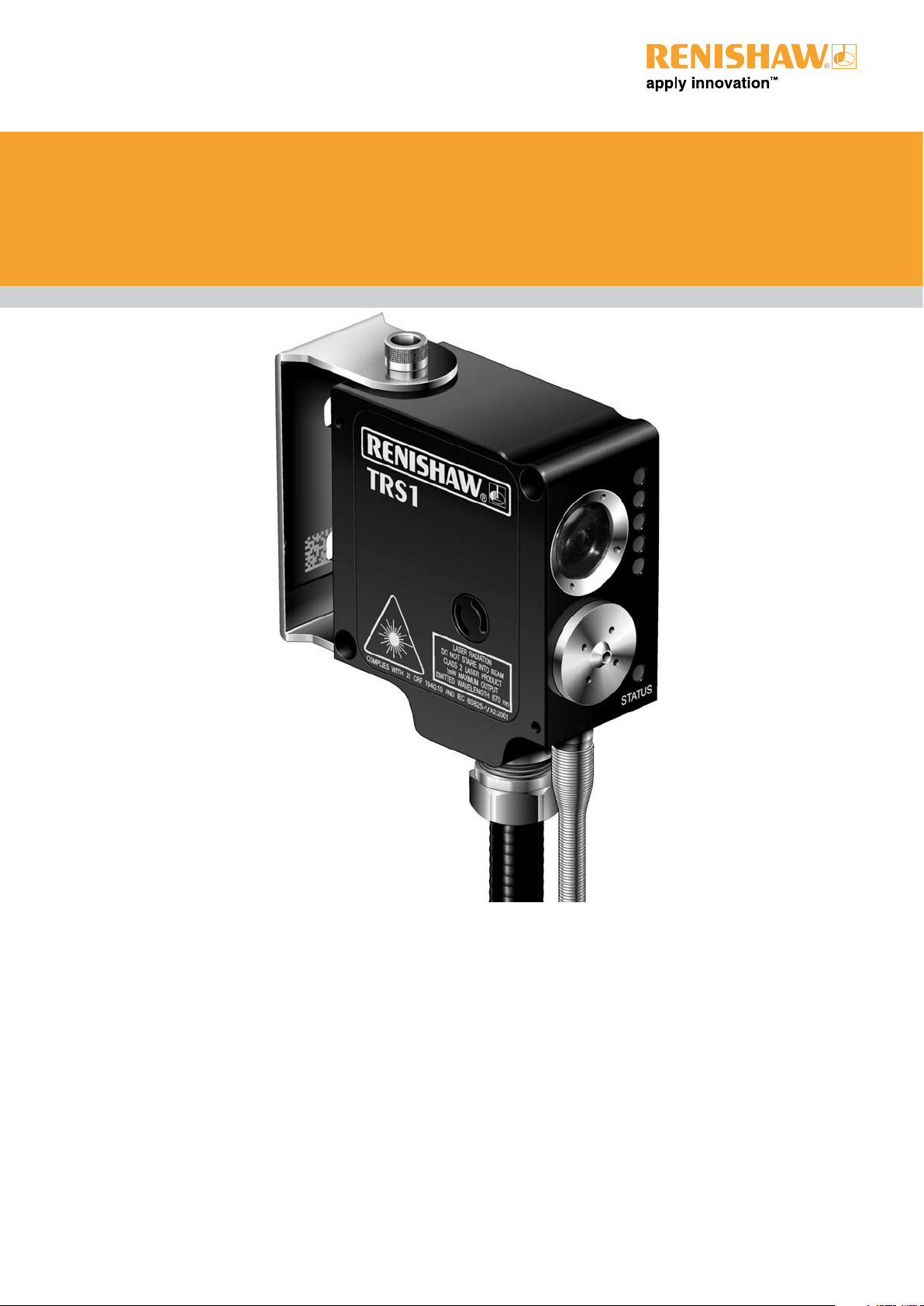
TRS1 non-contact broken tool
detection system - Mazak controls
Page 2

© 2005 Renishaw plc. All rights reserved.
This document may not be copied or reproduced in whole or in
part, or transferred to any other media or language, by any means,
without the prior written permission of Renishaw.
The publication of material within this document does not imply
freedom from the patent rights of Renishaw plc.
Disclaimer
Considerable effort has been made to ensure that the contents of
this document are free from inaccuracies and omissions. However,
Renishaw makes no warranties with respect to the contents of
this document and specifically disclaims any implied warranties.
Renishaw reserves the right to make changes to this document
and to the product described herein without obligation to notify any
person of such changes.
Trademarks
RENISHAW® and the probe emblem used in the RENISHAW logo
are registered trademarks of Renishaw plc in the UK and other
countries.
apply innovation is a trademark of Renishaw plc.
All other brand names and product names used in this document
are trade names, service marks, trademarks, or registered
trademarks of their respective owners.
Renishaw part no: H-2000-6411-00-A
Issued: November 2005
Page 3

Contents 1
Contents
TRS1 non-contact broken tool detection system ................................................................ 2
Machine spindle speed checking .................................................................................... 2
Software memory requirements ...................................................................................... 2
Machine tool controllers supported.................................................................................. 2
Measurement values used in this guide..........................................................................3
Installing the software...................................................................................................... 3
Setting data in macro (O1000 or O1001) ........................................................................ 3
Broken tool detection – (macro O1000/O1001) .................................................................. 5
Alternative program calling methods................................................................................... 7
Other parameter settings .................................................................................................. 10
Error messages and alarms.............................................................................................. 13
Publication No. H-2000-6411
Page 4

2 Broken tool detection
TRS1 non-contact broken tool detection system
This guide describes how to use the TRS1 non-contact broken tool detection system
software. The TRS1 is a laser non-contact system that provides high-speed/high accuracy
broken tool detection for solid tools only. As tools are moved into the laser beam, the
system detects reflection. Output signals are sent to the controller and the presence of the
tool can be established. The TRS1 system allows the following parameters to be
established:
z Detection of a broken tool.
NOTE: Solid tools – this means a tool where the cutting teeth do not protrude below the
centre point of the tool. Tools such as drills, taps, etc. are considered suitable tools.
Machine spindle speed checking
All broken tool detection takes place at a fixed spindle speed of 1000 rpm.
The active spindle speed is stored at the beginning of the broken tool macro. The broken tool
checking then takes place at 1000 rpm before resto ring the spin dle spee d back to its original
rpm.
Software memory requirements
Two Programs are supplied, if the broken tool check is to be called from a Mazatrol
program then O1001 will need to be loaded to the control. If the program is going to be
called from the ISO side the O1000 will require loading.
If the TRS1 is to be used in both Mazatrol and ISO then both programs can be loaded.
z O1000 (broken tool check ISO) 1.5 kb (3.75 metres) of memory.
z O1001 (broken tool check Mazatrol) 1.15 kb (2.875 metres) of memory.
Machine tool controllers supported
TRS1 system software is suitable for use on the following machine tool controllers.
M32,M-Plus,Fusion 640
Publication No. H-2000-6411
Page 5

Broken tool detection 3
Measurement values used in this guide
Throughout this guide, metric units of measurement, i.e. millimetres, are used in the
examples. The equivalent imperial measurements, i.e. inches, are shown in brackets.
Installing the software
Before installing the TRS1 software, read the guidelines contained in the readme file on
the CD.
Setting data in macro (O1000 or O1001)
Read the following variable descriptions then edit macro O1000 as described.
#14 = ‘X’ axis laser beam position. This defines the position at which broken tool
checking will take place in the X axis. (Machine positional values are
required).
Default: 0
NOTE: If the installation requires no X move to position the tool in the beam, then #14
requires no adjustment.
#15 = ‘Y’ axis laser beam position. This defines the position at which broken tool
checking will take place in the Y axis. (Machine positional values are
required).
Default: 0
NOTE: If the installation requires no Y move to position the tool in the beam, then #15
requires no adjustment.
#16 = ‘Z’ axis laser beam position. This defines the position at which broken tool
checking will take place in the Z axis. (Machine positional values are
required).
Default: 0
Publication No. H-2000-6411
Page 6

4 Broken tool detection
#17= Tool offset type.
1= Tool lengths stored in Mazatrol tool data.
2= Tool lengths stored in tool offsets (type A).
3= Tool lengths stored in ISO Tool data.
4= Tool lengths stored in tool offsets (type B).
#18= Skip code
This setting must be checked. With the incorrect setting the machine will
not detect a broken tool.
The machine should be connected so that G31.2 is used for the TRS1
move. If the machine is wired differently, change #18 to suit the skip
command being used. The default value is #18= 31.2.
Publication No. H-2000-6411
Page 7

Broken tool detection 5
Broken tool detection – (macro O1000/O1001)
NOTE: The TRS1 can perform a broken tool detection cycle only on solid tools.
Solid tools – this means a tool where the cutting teeth do not protrude below th e centre point
of the tool. Tools such as drills and taps are considered suitable.
Macro O1000/O1001 is used to check for breakage of solid cutting tools. The broken tool
cycle uses a plunge check, where the tool is moved into and out of the laser beam in the
spindle axis.
Typically, a tool needs to be checked after a machining operation, to verify that it is not
broken, before the next tool is selected.
Description
Detection of a broken tool occurs while the tool is r ota te d in the be am . M oves into and o ut of
the beam are at the rapid feedrate.
Publication No. H-2000-6411
Page 8

6 Broken tool detection
The tool first moves in rapid traverse to the checking position in the spindle axis using the
active tool length offset. The tool will then move at rapid traverse to the radial checking
position if this is required.
NOTE: The checking position must be on a perpendicular section of the tool, the fla nk a ngle
of a drill not being a suitable checking position.
The NC system then checks for the condition of the tool. The system looks for a signal within
a 30 second time-frame and if after 30 seconds no signal is received then a broken tool alarm
is raised.
The 30 second time-frame is attained by moving the spindle axis .50 mm @ F1. This can be
adjusted by the installer.
If the ‘Z’ macro input is used the tool retracts out of the beam to the position requested.
NOTE: If the ‘Z’ input is omitted the tool will retract to the spindle axis reference position.
Format - ISO/EIA
G65 P1000 [Hh Mm Zz Ss Ii Jj]
where [ ] denotes optional inputs
Example G65 P1000 H1.5 M1. Z10 I.1 J-.25
Subroutine inputs
The following inputs are used with this subroutine:
H Tolerance value that defines when the tool is out of tolerance.
NOTE: If the H input is used with a minus value assigned then the tool check position will
be the tool length plus the tolerance value.
Default value: 3.0 mm (0.0197 in).
M1. Tool broken flag.
Using this flag prevents a BROKEN TOOL alarm from being raised.
Z Safety plane.
The distance (in the spindle axis) to which the tool is retracted.
Default value: Spindle axis Reference position
Publication No. H-2000-6411
Page 9

Broken tool detection 7
S Spindle speed
Spindle speed at which checking for a broken tool takes place.
Default value: 1000
I Incremental adjustment distance (X axis).
This input allows the reflection point on the tool to be individually adjusted
to attain maximum feedback.
NOTE: Only valid if a X move is used to position the tool to its checking
position.
Default value: 0
J Incremental adjustment distance (Y axis).
This input allows the reflection point on the tool to be individually adjusted
to attain maximum feedback.
NOTE: Only valid if a Y move is used to position the tool to its checking
position.
Default value: 0
Outputs
The following output is always set when this cycle is executed:
#148 Broken tool flag.
(1 = broken tool, 0 = good tool)
NOTE: If #148 cannot be used, edit lines 10 and 60 in the macro program for a suitable
replacement.
Alternative program calling methods
The broken tool cycle can be called using an ‘M’ code. This ‘M’ code can be called directly
from Mazatrol or the ISO/EIA program.
To enable a ‘M’ code call the following parameters will need to be set
Publication No. H-2000-6411
Page 10

8 Broken tool detection
J73=1000 J74=350 J75=1 J76=1
J77=1001 J78=351 J79=1 J80=1
G65P1000 becomes M350.
G65P1001 becomes M351
Format - Mazatrol using M code call
Or
Publication No. H-2000-6411
Page 11

Broken tool detection 9
Format - ISO/EIA
G81Z-10.F100
G80
Or
M350
Or
M350Z100.
Or
G65P1000Z100.
Publication No. H-2000-6411
Page 12

10 Broken tool detection
Other parameter settings
The software supplied has O1000 as the program number, this can be edited by the
installer to suit. If a 9000 series number is selected the following parameters can be set.
9000–series program lock
F81.0 1=locked
0=unlocked
9000-series programs displayed
F81.1 1=not displayed
0=displayed
Tool offset and tool data handling parameters
The following parameters control how ISO/EIA programs handle tool offset or tool data.
The recommended settings are as follows:
F93.3=1 Tool lengths stored in Mazatrol,
and F94.7=1 and can be applied in an ISO/EIA program.
F93.3=0 Tool lengths stored in ISO tool offsets, and are applied in an ISO/EIA
and F94.7=0 program.
F93.3 Tool length of tool data for EIA/ISO program
0: Invalid
1: Valid
F94.7 Tool offset amount effectuated in an EIA/ISO program.
0: effectuates tool offset amount on the TOOL OFFSET display.
1: effectuates tool offset amount for EIA/ISO program on the TOOL DATA
display.
K69-K71 G31.1 – G31.3 Skip conditions.
These parameters control where G31.1 to G31.3 codes will look for a
trigger signal. See below for which parameter bit controls which input
codes G31.1-G31.3 will look at.
Bit 0 diagnostic X178 (XSKIP plug pin no.2)
Bit 1 diagnostic X179 (XSKIP plug pin no.10)
Bit 2 diagnostic X17A (XSKIP plug pin no.3)
Bit 3 diagnostic X17B (XSKIP plug pin no.11)
Publication No. H-2000-6411
Page 13

Broken tool detection 11
The normal setting for these parameters are:
K69 = 00000010 G31.1 looks at X179
K70 = 00000100 G31.2 looks at X17A
K71 = 00001000 G31.3 looks at X17B
NOTE: On machines (FH4800) with high speed spindles that require cycling to pre-warm
them, use the last probing (XSKIP pin 11).
Alarms
The following alarms may be generated when this cycle is executed.
BROKEN TOOL
NO H OFFSET ACTIVE
FORMAT ERROR
For an explanation of the meaning of alarms, see “Error messages and alarms” on
page 13.
Publication No. H-2000-6411
Page 14

12 Broken tool detection
Example: Broken tool detection
O????
M6Tt1 (Adjust to suit machine)
G43 H1 Z200.
(complete the machining sequence with tool T1)
G65 P1000 H5. Z25. Make a broken tool check. Either a BROKEN TOOL alarm is
M6Tt2 Select the next tool and continue.
(continue machining)
If the broken tool flag method is used, the cycle call is modified as follows:
raised and the program stops, or the program continues.
G65 P1000 H2. M1. Z25. S1000
Make a broken tool check without raising an alarm.
The #148 flag is set.
IF[#148EQ1]GOTO100
(continue program)
Block N100 will contain corrective actions. For example, selecting a sister tool for use or
selecting a new pallet/component.
Publication No. H-2000-6411
Page 15

Error messages and alarms
When an error state is detected, an error message is displayed on the screen of the
controller. Error messages, their meaning, and typical actions needed to clear them are
described below.
Message BROKEN TOOL
Meaning The tool is out of tolerance.
Action Replace the defective tool and establish the correct tool offset value.
Message NO H OFFSET ACTIVE
Meaning There is no active tool offset.
Action Correct the part program and run the program again.
Error messages and alarms 13
Message FORMAT ERROR
Meaning A macro input is either missing or the value entered is incorrect.
Action Correct the macro input line then run again.
Publication No. H-2000-6411
Page 16

Page 17

Renishaw plc
New Mills, Wotton-under-Edge,
Gloucestershire, GL12 8JR
United Kingdom
T +44 (0)1453 524524
F +44 (0)1453 524901
E uk@renishaw.com
www.renishaw.com
For worldwide contact details,
please visit our main web site at
www.renishaw.com/contact
*H-2000-6411-00*
 Loading...