


Installation and user’s guide
H-2000-5219-01-A
RMP60 - radio probe
© 2003 Renishaw. All rights reserved.
Renishaw® is a registered trademark of Renishaw plc.
This document may not be copied or reproduced in whole or in part, or transferred to any other media or
language, by any means, without the prior written permission of Renishaw.
The publication of material within this document does not imply freedom from the patent rights of Renishaw plc.
Renishaw Part no: H-2000-5219-01-A
Issued: 08.2003
Disclaimer
Considerable effort has been made to ensure that the contents of this document are free from inaccuracies and omissions. However, Renishaw makes no warranties with respect to the contents of this document and specifically disclaims any implied warranties. Renishaw reserves the right to make changes to this document and to the product described herein without obligation to notify any person of such changes.
Trademarks
All brand names and product names used in this document are trade names, service marks, trademarks, or registered trademarks of their respective owners.

1
EC DECLARATION OF CONFORMITY
Renishaw plc declare that the product: -
Name: RMP60
Description: Radio machine probe
has been manufactured in conformity with the following standard: -
BS EN 61326:1998/ Electrical equipment for measurement, control and laboratory use - EMC requirements.
Immunity to annex A - industrial locations. Emissions to class A (non-domestic) limits.
and that it complies with the requirements of directive (as amended): -
89/336/EEC |
- Electromagnetic compatibility |
The above information is summarised from the full EC declaration of conformity. A copy is available from Renishaw on request.
2 |
Installation and user’s guide |
Installation and user’s guide
Warranty
Equipment requiring attention under warranty must be returned to your supplier. No claims will be considered where Renishaw equipment has been misused, or repairs or adjustments have been attempted by unauthorised persons.
Changes to equipment
Renishaw reserves the right to change specifications without notice.
CNC machine
CNC machine tools must always be operated by competent persons in accordance with manufacturers instructions.
Care of the probe
Keep system components clean and treat the probe as a precision tool.
Patent notice
Features of products shown in this guide, and of related products, are the subject of the following patents and/or patent applications:
EP 0652413
US 4599524
US 5,279,042
JP 3,126,797
WO 02/063235
WO 03/021182

Contents 3
Contents |
|
Typical probe system with radio |
|
transmission .................................................... |
4 |
System performance ...................................... |
5 |
Operating envelope ......................................... |
6 |
RMP60 features .............................................. |
7 |
RMP60 specification ....................................... |
8 |
Probe status LED ............................................ |
9 |
Weak link stem ................................................ |
9 |
Modes of operation ....................................... |
10 |
Reviewing current probe settings ................ |
12 |
Configuration using trigger logic ................... |
13 |
System setup/establishing |
|
RMP60/RMI partnership ............................... |
15 |
RMP60 batteries ........................................... |
17 |
Battery life expectancy ................................. |
19 |
RMP60/shank mounting ............................... |
21 |
Stylus on-centre adjustment ......................... |
22 |
Stylus trigger force adjustment ..................... |
23 |
Probe moves ................................................. |
24 |
Software requirements .................................. |
26 |
Typical probe cycles ..................................... |
27 |
Diaphragm replacement ................................ |
29 |
Fault finding .................................................... |
31 |
Appendix 1 RMI ........................................... |
36 |
Parts list ......................................................... |
38 |
4 |
Typical probe system with radio transmission |
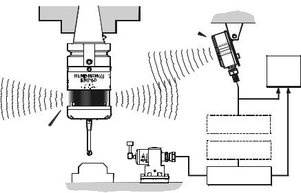
Typical probe system with radio transmission
CNC machining centre spindle
RMI
Interface
RMP60 inspectionprobe
Probe status LEDs |
Typical tool setting probe |
Stylus
Cable
RMI mounting bracket
C N C machine control
Optional - PSU3 power supply unit
Optional - PSU3 power supply unit
Workpiece |
Interface unit |
A workpiece set-up and inspection probe is in effect another tool in the system.
A probing cycle may be included at any stage of the machining process.
Probe data signals are transmitted via radio link to the RMI and on to the machine control. The RMI converts probe signals into an acceptable form for the machine control.
System performance |
5 |
System performance
Operating envelope
Surfaces within the machine may increase the signal transmission range.
Coolant and swarf residue accumulating on the RMP60 and RMI may have a detrimental effect on transmission performance. Wipe clean as often as is necessary to maintain unrestricted transmission.
When operating, do not touch with your hand, either the RMI cover or the probe glass window, as this will change the performance.
Operation in extremes of temperature will result in some reduction in range.
RMI position
To assist finding the optimum position of the RMI during system installation, a signal strength indication LED is available on the RMI interface.
RMI signal strength is displayed on an RMI multi-coloured LED.
Environment
RMP60 |
Temperature |
|
RMI |
||
PSU3 |
|
|
|
|
|
Storage |
-10 °C to 70 °C |
|
(14 °F to 158 °F) |
||
|
||
|
|
|
Normal |
5 °C to 50 °C |
|
operating |
(41 F° to 122 °F) |
|
|
|
Probe repeatability
Maximum 2 Sigma (28) Value
Repeatability of 1,0 µm (40 µ in) is valid for test velocity of 480 mm/min (1.57 ft/min) at stylus tip, using stylus 50 mm (1.97 in) long.

6 Operating envelope
Operating envelope
RMP60 probe + RMI |
|
|
|
|
Range metres (feet) |
|
|
||
|
|
|
|
OPERATING AND SWITCH ON/OFF |
|||||
RMP60 and RMI must be within each others |
|||||||||
|
|
|
|
||||||
operating envelope shown. |
|
|
|
75° |
15 (49) |
|
|||
|
75° |
90° |
75° |
|
60° |
|
|
||
|
|
|
|
|
10 (33) |
|
|||
60° |
|
|
|
|
60° |
|
|
||
|
|
|
|
|
|
|
|||
45° |
|
|
|
|
45° |
|
|
||
|
|
|
|
45° |
|
|
5 (16) |
||
|
|
|
|
|
|
|
|
||
30° |
|
|
|
|
30° |
|
|
|
|
15° |
|
|
|
|
15° |
|
|
|
|
0° |
|
|
|
|
0° |
|
|
5 |
|
|
|
|
|
|
|
|
|
(16) |
|
15° |
|
|
5 |
|
15° |
15° |
|
10 |
|
|
|
(1 6) |
|
|
|
|
|||
|
|
|
|
|
|
(33) |
|||
|
|
10 10 |
|
|
30° |
|
|||
|
|
|
|
|
|
||||
30° |
|
(33) |
(33) |
|
|
|
|
||
|
|
30° |
|
|
15 |
||||
|
|
15 |
15 |
|
|
|
45° |
||
|
|
|
|
|
(49) |
||||
45° |
|
|
45° |
|
60° |
||||
|
(49) |
(49) |
|
|
75° |
||||
60° |
|
|
|
|
60° |
|
|
|
|
|
75° |
90° |
75° |
|
|
|
|
||
|
|
|
|
|
|
|
|||
RMP60 features |
7 |
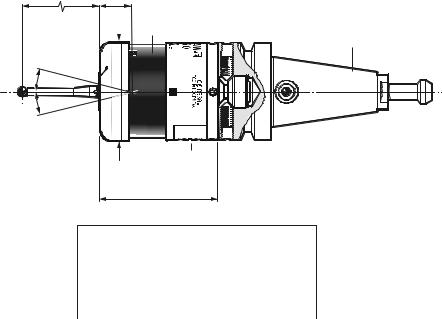
RMP60 features
50 (1.97) |
19 (0.75) |
RMP60 window
M4 stylus |
18° |
18° |
Battery cover
Ø63 (Ø2.48)
76 (2.99)
STYLUS OVERTRAVEL LIMITS
Dimensions mm (in)
A range of probe ready shanks is available from Renishaw upon request
Stylus length |
±X / ±Y |
Z |
|
|
|
|
|
50 (1.96) |
21 |
(0.82) |
11 (0.43) |
100 (3.93) |
37 |
(1.45) |
11 (0.43) |
|
|
|
|
|
|
|
|

8 |
RMP60 specification |
RMP60 specification
Stylus trigger force
X/Y trigger forces vary, depending on trigger direction. There are 3 high force and 3 low force directions
X/Y direction |
Typical lowest force |
(50 mm stylus) |
0.75 N / 75 gf |
|
(2.64 ozf) |
|
Typical highest force |
|
1,4 N / 140 gf (4.92 ozf) |
Z direction |
4.90 N / 490 gf |
|
(17.28 ozf) |
RMP60 IP rating |
IPX8 |
RMP60 weight |
Without batteries |
(without shank) |
855 g (30.16 oz) |
|
With batteries |
|
901 g (31.79 oz) |
PROBE STATUS LED
LED |
Probe status |
Graphic hint |
|
colour |
|||
|
|
||
Unlit |
Stand-by mode |
|
|
Flashing |
Probe seated in |
|
|
green |
operating mode |
|
|
Flashing |
Probe triggered in |
|
|
red |
operating mode |
|
|
Flashing |
Probe seated in |
|
|
green |
operating mode |
|
|
and blue |
- low battery |
|
Flashing Probe triggered in red and operating mode blue - low battery
Constant
Battery dead
red
Max spin speed 1000 rev/min
Probe status LED |
9 |
Probe status LED
LEDs |
19 mm |
|
LEDs |
flashing |
|
flashing |
|
GREEN |
|
|
RED |
|
X / Y |
|
|
Weak link (steel styli only) |
18° 18° |
|
|
Fitting stylus with weak |
|
|
|
link onto RMP60 |
Fitting a weak link |
||
In the event of
2 Nm (1.7 lbf.ft)
excessive stylus
overtravel the weak link is designed
to break, thereby protecting the probe from damage.
Take care to avoid stressing the weak link during assembly.
5 mm AF
2 Nm (1.7 lbf.ft)
12 mm
(0.47 in)
Z
11 mm
Removing a broken weak link

10 Modes of operation
Modes of operation
The RMP60 probe can be in one of three modes:
1.Stand-by mode - The RMP60 is waiting for a switch-on signal .
2.Operating mode - Activated by one of the switch on methods described on this page. In this mode and the RMP60 is now ready for use.
3.Configuration mode - The trigger-logic configuration method allows a number of RMP60 set-up options to be configured by triggering the RMP60, including the switch-off options described on page 25.
RMP60 switch-on
RMP60 power on/off
Switch-on options are configurable
- see page 13.
Three switching methods can be used.
1.Radio start
Radio switch-on is commanded by
M code.
2.Spin start
Spin at 650 rev/min for 1 sec minimum (maximum 6 sec)
3.Shank switch
Note:
RMP60 will be turned on after 1 sec in all modes.
|
|
|
|
Modes of operation |
11 |
|
|
|
|
|
|
|
|
|
RMP60 switch-off |
|
|
|
|
|
|
|
|
|
|
|
|
|
Switch-off options are programmable |
3. |
Spin stop |
|
|
|
|
Three switching methods can be used. |
|
|
(Only applies when spin on mode is |
|
|
|
1. Radio stop |
|
|
selected). |
|
|
|
|
|
|
|
|
|
|
Radio switch off is commanded by a |
|
|
A timer switch automatically swiches |
|
|
|
|
|
the probe off after 90 min from last |
|
|
|
|
M code. |
|
|
|
|
|
|
|
|
trigger off, if not spun off. |
|
|
|
|
|
|
|
|
|
|
|
(Only applies when radio turn on is |
|
|
|
|
|
|
selected). |
4. |
Shank switch |
|
|
|
|
|
|
|
|||
|
A timer automatically switches the probe off |
|
|
(Only applies when shank on mode is |
|
|
|
after 90 min from last trigger if not turned off |
|
|
selected). |
|
|
|
by M-code. |
|
|
|
|
|
|
2. Timer off (time out) |
|
|
|
|
|
|
|
|
|
|
|
|
|
|
Note: |
|
|
||
|
(Only applies when radio on/spin on |
|
|
|
||
|
|
After being turned on, the RMP60 must be |
|
|
||
|
mode is selected). |
|
|
|
||
|
|
on for a minimum of 1 sec (7 sec for spin |
|
|
||
|
The RMP60 will time out (12, 33 or |
|
|
|
||
|
|
off) before being turned off. |
|
|
||
|
134 sec) after the last probe trigger or |
|
|
|
||
|
|
|
|
|
|
|
|
reseat. |
|
|
|
|
|
|
|
|
|
|
|
|
|
|
|
|
|
|
|
 Loading...