

Page 1
Installation and user’s guide
H-1000-5131-01-A
TP20 probe for FARO arm
Page 2

© 2007 Renishaw plc. All rights reserved.
This document may not be copied or reproduced in whole or in part, or
transferred to any other media or language, by any means, without the
prior written permission of Renishaw.
The publication of material within this document does not imply freedom
from the patent rights of Renishaw plc.
Disclaimer
Considerable effort has been made to ensure that the contents of this
document are free from inaccuracies and omissions. However, Renishaw
makes no warranties with respect to the contents of this document and
specifically disclaims any implied warranties. Renishaw reserves the right
to make changes to this document and to the product described herein
without obligation to notify any person of such changes.
Trademarks
RENISHAW® and the probe emblem used in the RENISHAW logo are
registered trademarks of Renishaw plc in the UK and other countries.
apply innovation is a trademark of Renishaw plc.
All other brand names and product names used in this document are
trade names, service marks, trademarks, or registered trademarks of their
respective owners.
Renishaw part no: H-1000-5131-01-A
Issued: 12 2007
Page 3

TP20 probe for FARO arm
installation and user’s guide
1
Page 4

2
Care of equipment
Renishaw probes and associated systems are precision tools used for
obtaining precise measurements and must therefore be treated with
care.
Changes to equipment
Renishaw reserves the right to improve, change or modify its hardware
or software without incurring any obligations to make changes to
Renishaw equipment previously sold.
Warranty
Renishaw plc warrants its equipment provided that it is installed
exactly as defined in associated Renishaw documentation.
Prior consent must be obtained from Renishaw if non-Renishaw
equipment (e.g. interfaces and/or cabling) is to be used or substituted
for Renishaw equipment. Failure to comply with this will invalidate the
Renishaw warranty.
Claims under warranty must be made from authorised service
centres only, which may be advised by the supplier or distributor.
Patents
Aspects of the TP20 probing system and aspects of similar systems
are the subject of the following patents and patent applications.
Care of equipment
EP 548328
EP 750171
EP 501710
EP 826136
EP 566719
JP 3294269
JP JP 3279317
JP 2,510,804
JP 505,622/1999
US 5,323,540
US 5,505,005
US 5,327,657
US 5,404,649
US 5,339,535
US 5,918,378
US 6012230
Page 5

Contents
Contents
1 Introduction ...................................................................................4
2 Product description .......................................................................5
2.1 The FARO TP20 touch-trigger probe kit ............................... 5
2.1.1 The probe body .......................................................5
2.1.2 The probe modules.................................................. 7
3 Product installation ........................................................................ 9
3.1 Fitting the TP20 probe onto a FARO arm ............................. 9
3.2 Fitting a stylus onto the probe module .................................9
3.3 Fitting the probe module and stylus onto the probe body ..11
4 Technical data - TP20 probe module changing touch-trigger probe .. 12
4.1 Measuring performance .....................................................12
4.1.1 Probing forces and overtravel limits ....................... 13
4.1.2 Probe module changing repeatability .................... 13
4.1.3 Technical specification ........................................... 14
5 Applications guide ....................................................................... 15
5.1 Probe module selection ......................................................15
5.1.1 The low force probe module .................................. 16
5.1.2 The standard force probe modules ........................16
5.1.3 The medium force probe module ...........................16
5.1.4 The extended force probe module .........................16
5.1.5 The 6-way probe module ....................................... 16
5.2 Stylus selection ..................................................................17
5.2.1 Recommended stylus limits ................................... 19
6 Product maintenance .................................................................. 24
3
Page 6
4
Introduction
1 Introduction
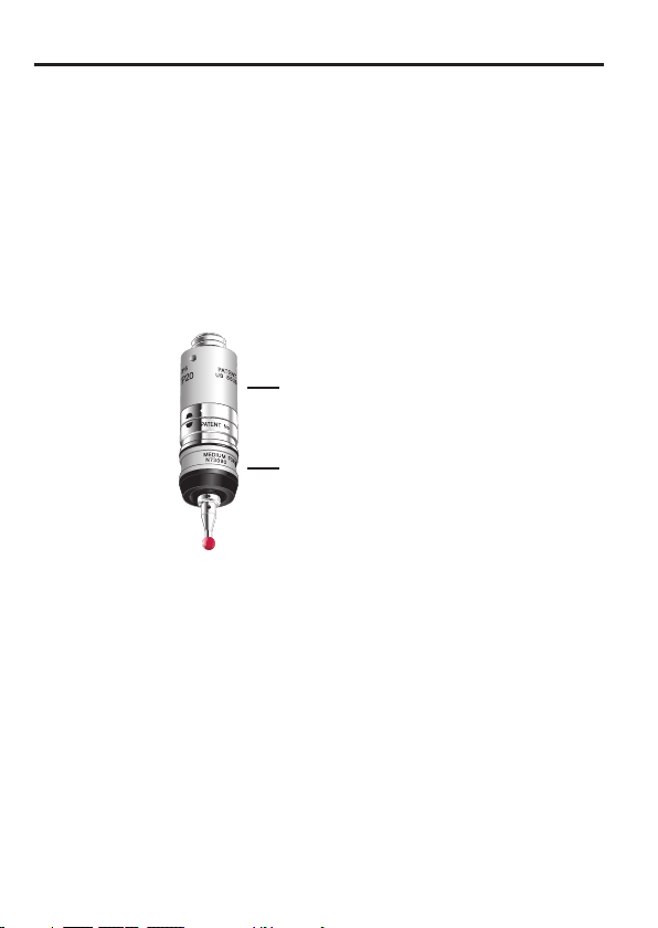
The Renishaw TP20 probe module changing touch-trigger probe is
a 5-way or 6-way kinematic probe with the facility to change stylus
configurations without the need for re-qualification.
The TP20 comprises a two-piece design – a probe body and
detachable probe module(s).
TP20 probe body
TP20 probe module
changing touchtrigger probe
Figure 1 - The TP20 probe
Page 7

Product description
2 Product description
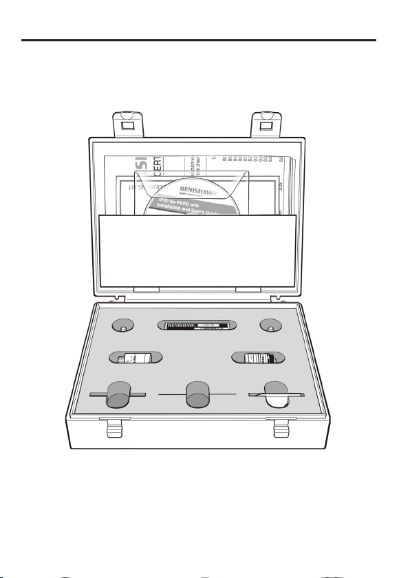
2.1 The FARO TP20 touch-trigger probe kit
The standard Renishaw TP20 touch-trigger probe kit (see figure 2)
comprises the following primary components:
• One TP20 probe body
• One medium force TP20 probe module (see page 8 for available
combinations)
• Ø 6 mm (0.24 in) x 10 mm (0.39 in) stylus
• Ø 2 mm (0.08 in) x 10 mm (0.39 in) stylus
• Probe and stylus tools
2.1.1 The probe body
The probe body incorporates a standard Renishaw M8 × 1.25 screw
connector mount and is designed to house the mating half of the
probe module’s kinematic coupling.
5
Page 8
6
Product description
Figure 2 - The TP20 probe for FARO arm kit
Page 9

Product description
2.1.2 The probe modules
Each probe module, which houses the kinematic switching touch
sensor mechanism, carries the stylus assembly and provides
overtravel in the X, Y and +Z axes (–Z is offered when using the TP20
6-way probe module). Incorporating an M2 stylus mounting, each
probe module is compatible with Renishaw’s comprehensive range of
M2 styli.
Designed to minimise the possibility of probe module misalignment
generating a probe ‘seated’ signal, the probe module is held in position
by a magnetically retained, highly repeatable kinematic coupling.
Electrical contact pins conduct the probe sense voltage through the
coupling.
Trigger force options
The standard force probe module is suitable for most applications
(when used with the recommended stylus range), but sometimes the
effects of stylus length and mass, combined with acceleration and
vibration, can cause the probe to false trigger (these are referred to as
‘spurious triggers’).
To allow the TP20 to be used where acceleration forces would
otherwise result in spurious touches, a choice of higher force probe
modules is available. A low force probe module is also available for
measurement of delicate materials. Refer to the applications guide
later in this document for information on how to select the correct
probe module for your application.
7
Page 10

8
The type of probe modules supplied with your probe will be clearly
marked on each probe module’s front ring. The probe modules also
carry a colour-coded front cap as follows:
• Low force (LF) probe module (green cap)
• Standard force (SF) probe module (black cap)
• Medium force (MF) probe module (grey cap) (supplied)
• Extended force (EF) probe module (brown cap)
• 6-way (6W) probe module (blue cap)
• Extension module 1 standard force (EM1 STD) (black cap)
• Extension module 2 standard force (EM2 STD) (black cap)
The following TP20 probe module kits are available from your supplier:
Product description
TP20 probe module kit
(probe module only)
Low force probe module A-1371-0392
Standard force probe module A-1371-0270
Medium force probe module A-1371-0271
Extended force probe module A-1371-0272
6-way probe module A-1371-0419
EM1 STD probe module A-1371-0430
EM2 STD probe module A-1371-0431
EM1 STD and EM2 STD probe modules A-1371-0432
Part number
Page 11

Product installation
3 Product installation
3.1 Fitting the TP20 probe onto a FARO arm
To fit the TP20 probe carry out the following procedure (see figure 3):
1. By hand, screw the threaded end of the probe body into the TP20
adaptor and finger tighten to secure.
2. Fit the S1 ‘C’ wrench (supplied) onto the probe body as shown in
Figure 3.
3. Using the S1 ‘C’ wrench, fully finger tighten the probe body into
the M8 bush (0.3 Nm – 0.5 Nm).
3.2 Fitting a stylus onto the probe module
To fit a stylus onto the probe module, carry out the following procedure
(see figure 3):
1. Screw the threaded end of your chosen stylus into the M2 stylus
mount of the probe module and finger tighten to secure.
2. Using the type S7 stylus tools provided, or type S20 wrench if
fitting a stylus from the Renishaw GF range, fully finger tighten
the stylus into the stylus mount to achieve the recommended
tightening torque of between 0.05 Nm and 0.15 Nm (maximum
permissible torque is 0.3 Nm).
9
NOTE: For advice on both stylus and probe module selection, refer to
the applications guide later in this publication.
Page 12

10
Product installation
Probe body
Probe module
TP20 adaptor
S1 ‘C’ wrench
S7 stylus tool
M2 stylus
Figure 3 - Fitting the TP20 probe onto the FARO adaptor
Page 13

Product installation
11
3.3 Fitting the probe module and stylus onto the probe
body
To fit the probe module and stylus onto the probe body, carry out the
following procedure (see figure 4):
1. Visually examine the mating faces of both the probe module
and the probe head for cleanliness; where necessary, clean the
mating surfaces using the CK200 cleaning kit (supplied).
2. Offer up the probe module to the probe body and, ensuring the
three alignment marks on both the probe module and probe
body are correctly aligned, allow the probe module to engage the
probe body under magnetic force.
Alignment marks
Alignment marks
Figure 4 - Fitting the probe module and stylus onto the probe body
Page 14

12
Technical data
4 Technical data - TP20 probe module
changing touch-trigger probe
4.1 Measuring performance
NOTE: The following data is derived from high accuracy test rig
measurements and may not represent the performance achievable
on an arm. Please consult your supplier for overall system accuracy
information.
Performance at 10 mm stylus length
Parameter Probe module type
LF SF MF EF 6-way EM1
Unidirectional
repeatability*
(2s)
2D (XY) form
measurement
deviation*
* Measured at a trigger speed of 8 mm/s
Test stylus ball diameter 4 mm
0.35 µm0.35 µm0.50 µm0.65 µm0.8 µm0.35 µm0.35
±0.6 µm±0.8 µm±1.0 µm±2.0 µm±1.5 µm±0.8 µm±0.8
STD
EM2
STD
µm
µm
Page 15

4.1.1 Probing forces and overtravel limits
Technical data
13
Probe
module
type and
stylus
length
LF
10 mm
SF
10 mm
MF
25 mm
EF
50 mm
6-way
10 mm
EM1 STD
10 mm
EM2 STD
10 mm
Trigger force
(nominal at
stylus tip)
XY Z XY +Z -Z XY +Z -Z
0.055 N
(5.5 gf)
0.08 N
(8 gf)
0.1 N
(10 gf)
0.1 N
(10 gf)
0.14 N
(14 gf)
0.08 N
(8 gf)
0.08 N
(8 gf)
0.65 N
(65 gf)
0.75 N
(75 gf)
1.9 N
(190 gf)
3.2 N
(320 gf)
1.6 N
(160 gf)
0.75 N
(75 gf)
0.75 N
(75 gf)
Parameter
Overtravel force*
(max. at stylus tip)
0.09 N
0.2-0.3 N
(20-30 gf)
0.2-0.4 N
20-40 gf)
0.2-0.5 N
(20-50 gf)
0.25 N
(25 gf)
0.2-0.3 N
(20-30 gf)
0.2-0.3 N
(20-30 gf)
(9 gf)
1.15 N
(115 gf)
3.5 N
(350 gf)
7.0 N
(700 gf)
10 N
(1kgf)
2.5 N
(250 gf)
3.5 N
(350 gf)
3.5 N
(350 gf)
- ±14°
- ±14°
- ±14°
- ±14°
9.0 N
(900 gf)
- ±14°
- ±14°
Overtravel
displacement*
3.1
mm
4.0
mm
3.7
mm
2.4
mm
4.5 mm1.5
±14°
4.0
mm
4.0
mm
* NOTE: The probe module may detach if this value is exceeded.
4.1.2 Probe module changing repeatability
Probe module changing Repeatability
Manual changing 2.0 µm
-
-
-
-
mm
-
-
Page 16

14
4.1.3 Technical specification
Technical data
Dimensions
Diameter
Probe mount
Stylus mount
Sense directions
Probe module pull-
off force
Sealing
Probe module life
Length
13.2 mm (0.52 in)
LF/SF/MF/EF 38 mm (1.5 in)
EM1 STD 88 mm (3.46 in)
EM2 STD 113 mm (4.45 in)
6-way 42 mm (1.65 in)
Thread M8 x 1.25 x 5 mm
Thread M2 x 0.4
LF/SF/MF/EF/
EM1 STD/EM2
STD
6-way 6-way (±X, ±Y, ±Z)
10 N (1 kgf) maximum
IP30
25,000 changes
5-way (±X, ±Y, +Z)
Page 17

Applications guide
5 Applications guide
5.1 Probe module selection
To obtain the best possible performance from your TP20 probe,
it is important to select the correct probe module for your specific
application. When choosing the probe module to be used, the
following considerations should be addressed:
• The mass of the stylus assembly and its centre of gravity. It is
always best to use the shortest stylus possible.
• The orientation of the probe body.
• The levels of acceleration and vibration to which the TP20 probe
will be subjected. These will vary with movement and velocity.
The following probe modules are available for use with the TP20
probe; each probe module is clearly marked on its front ring and also
carries a colour-coded front cap as follows:
• Low force probe module (green cap)
• Standard force probe module (black cap)
• Medium force probe module (grey cap) (supplied)
15
• Extended force probe module (brown cap)
• 6-way probe module (blue cap)
• EM1 STD probe module (black cap)
• EM2 STD probe module (black cap)
Page 18

16
5.1.1 The low force probe module
The low force probe module, identified by a green cap, is suited to
applications that require a low trigger force, for example rubber seals.
5.1.2 The standard force probe modules
The standard force probe modules (SF, EM1 STD and EM2 STD) are
identified by black caps and are suited to the majority of applications.
5.1.3 The medium force probe module
The medium force probe module, identified by a grey cap, is provided
for use where a higher trigger force than standard is required.
5.1.4 The extended force probe module
The extended force probe module is identified by a brown cap.
Typically, this probe module will only be required with large stylus
assemblies, and where spurious triggers caused by acceleration
preclude the use of either the standard or medium force probe
modules.
5.1.5 The 6-way probe module
The 6-way probe module is identified by a blue cap. This probe
module is designed for 6-way operation where there is a requirement
to measure in the –Z direction, for example when measuring
undercuts.
Applications guide
Page 19

Applications guide
17
5.2 Stylus selection
NOTE: Choosing the best stylus for a given application is an
important factor in achieving optimum probe performance. For
further information on the full range of Renishaw styli, please refer to
Renishaw’s styli and accessories brochure (H 1000-3200) which can
be ordered from your supplier or downloaded from Renishaw’s web
site, www.renishaw.com.
When selecting a stylus, it is important that the stylus length is kept to
the minimum required to access all features to be measured, and that
the stylus type offers the maximum possible stiffness. Factors that
affect stiffness are:
• Joints in the styli: that tend to reduce rigidity and should therefore
be kept to the absolute minimum.
• Stem diameters: that are governed by the ball tip diameter of the
stylus.
• Stem material: that can be stainless steel, ceramic or graphite
fibre (GF).
It is also important to ensure that the stylus ball diameter chosen is as
large as is practical. This not only ensures that the stylus will be as
stiff as possible, but also reduces the stylus’s susceptibility to surface
form and surface finish.
Page 20

18
Owing to the modular construction of the TP20, when selecting and
using styli the following criteria should be applied:
• Work only within the recommended stylus limits for each probe
• Always use the shortest possible stylus.
• If using larger styli than those recommended for use with each
• Minimise the mass of styli by using either ceramic or graphite
Applications guide
module (refer to Recommended stylus limits).
probe module, always conduct trials to establish the effect on
measuring performance.
fibre (GF) stems.
Page 21

Applications guide
5.2.1 Recommended stylus limits
Owing to the modular construction of the TP20 probe, it is
recommended that the limits shown in figures 5 to 9 are applied when
selecting styli to be used.
The medium force and extended force probe modules
The medium force and extended force probe modules have the
following recommended stylus limits:
• Any stylus type up to 60 mm (2.36 in) long.
• Star and cranked styli up to 20 mm (0.79) offset.
30 mm
(1.18 in)
60 mm
(2.36 in)
19
Min: 10 mm (0.39 in) Max: 40 mm (1.57 in)
Figure 5 - Recommended stylus limits for medium and extended force
probe modules
Page 22

20
The low force probe module
The low force probe module has the following recommended stylus
limits:
• Steel and carbide styli up to 30 mm (1.18 in) long
• No star or cranked styli
Applications guide
Max: 30 mm
(1.18 in)
Figure 6 - Recommended stylus limits for low force probe module
Page 23

Applications guide
The standard force probe modules
The standard force probe modules (SF, EM1 STD and EM2 STD) can
be used with the following range of styli:
• Steel and carbide styli up to 40 mm (1.57 in) long.
• Renishaw graphite fibre (GF) type styli up to 50 mm (1.97 in) long.
• Star and cranked styli up to 20 mm (0.79 in) offset.
20 mm
(0.79 in)
Steel: 40 mm
(1.57 in)
GF: 50 mm
(1.97 in)
21
Min: 10 mm (0.39 in) Max: 40 mm (1.57 in)
Figure 7 - Recommended stylus limits for standard force probe
modules
Page 24

22
The 6-way probe module
The recommended stylus limits for the 6-way probe module are:
• Any stylus type up to 30 mm (1.18 in) long
• Star and cranked styli up to 10 mm offset
Applications guide
Max: 20 mm
(0.79 in)
Max: 30 mm
Max: 20 mm (0.79 in)
Figure 8 - Recommended stylus limits for 6-way probe module
Page 25

Applications guide
Comparative stylus lengths
A comparison of the minimum and maximum stylus lengths for use
with each probe module is shown in figure 9.
LF
SF
MF
EF
6W
EM1 STD
EM2 STD
23
10 mm
(0.39 in)
Figure 9 - Comparative stylus lengths
50 mm
(1.97 in)
100 mm
(3.94 in)
Page 26

24
Product maintenance
6 Product maintenance
NOTE: Maintenance of the TP20 probe is restricted to the periodic
cleaning of the kinematic couplings of both the probe body and the
probe module(s). To aid cleaning of these couplings, each TP20 probe
is supplied with a Renishaw CK200 cleaning kit.
Each Renishaw CK200 cleaning kit contains a specialised material
to effectively remove contamination from the precision ball/V groove
seatings, electrical contacts and permanent magnets of the kinematic
couplings.
NOTE: When operating the TP20 probe in environments subjected
to airborne contamination, the user should determine the frequency
of cleaning required to ensure the kinematic couplings remains
uncontaminated.
Whilst the kinematic coupling mechanism is highly tolerant of nonmetallic dust, regular inspection and cleaning with the material
provided is recommended to ensure continued high performance.
Instructions for use are included with the cleaning kit. If required,
replacement kits can be ordered from your supplier (part number
A-1085-0016).
Probe modules that are not attached to the probe body should be
stored in their transport boxes, to prevent contamination.
Page 27

Renishaw plc
New Mills, Wotton-under-Edge,
Gloucestershire, GL12 8JR
United Kingdom
For worldwide contact details, please
www.renishaw.com/contact
T +44 (0)1453 524524
F +44 (0)1453 524901
E uk@renishaw.com
www.renishaw.com
visit our main website at
*H-1000-5131-01*
 Loading...