

Page 1
Touch-trigger probe systems - TP1, TP2, TP6, TP6A, PH1, PH5, PH6, PH6M
Document part number H-1000-5021-07-A
Touch-trigger probe systems - TP1, TP2, TP6, TP6A, PH1, PH5, PH6, PH6M
http://www.renishaw.com
Issued 11 2014
1
Page 2

General information
©19872014Renishawplc.Allrightsreserved.
This document may not be copied or reproduced in whole or in part, or transferred to any other media or language, by any means, without
the prior written permission of Renishaw.
The publication of material within this document does not imply freedom from the patent rights of Renishaw plc.
Disclaimer
RENISHAW HAS MADE CONSIDERABLE EFFORTS TO ENSURE THE CONTENT OF THIS DOCUMENT IS CORRECT AT THE DATE
OF PUBLICATION BUT MAKES NO WARRANTIES OR REPRESENTATIONS REGARDING THE CONTENT. RENISHAW EXCLUDES
LIABILITY, HOWSOEVER ARISING, FOR ANY INACCURACIES IN THIS DOCUMENT.
Trademarks
RENISHAW® and the probe emblem used in the RENISHAW logo are registered trademarks of Renishaw plc in the UK and other
countries.
apply innovation is a trademark of Renishaw plc.
All brand names and product names used in this document are trade names, service marks, trademarks, or registered trademarks of their
respective owners.
Windows XP, Windows 2000, Vista and Windows 7 are registered trade names of the Microsoft Corporation.
All trademarks and trade names are acknowledged.
WEEE
The use of this symbol on Renishaw products and/or accompanying documentation indicates that the product should not be mixed with the
general household waste upon disposal. It is the responsibility of the end user to dispose of this product at a designated collection point for
waste electrical and electronic equipment (WEEE) to enable reuse or recycling. Correct disposal of this product will help save valuable
resources and prevent potential negative effects on the environment. For more information, please contact your local waste disposal service
or Renishaw distributor.
Warranty
Renishaw plc warrants its equipment for a limited period (as set out in our Standard Terms and Conditions of Sale) provided that it is
installed exactly as defined in associated Renishaw documentation.
Prior consent must be obtained from Renishaw if non-Renishaw equipment (e.g. interfaces and/or cabling) is to be used or substituted.
Failure to comply with this will invalidate the Renishaw warranty.
Claims under warranty must be made from authorised service centres only, which may be advised by the supplier or distributor.
Touch-trigger probe systems - TP1, TP2, TP6, TP6A, PH1, PH5, PH6, PH6M
http://www.renishaw.com
Issued 11 2014
2
Page 3

Care of equipment
Renishaw probes and associated systems are precision tools used for obtaining precise measurements and must therefore be treated with
care.
Changes to Renishaw products
Renishaw reserves the right to improve, change or modify its hardware or software without incurring any obligations to make changes to
Renishaw equipment previously sold.
Touch-trigger probe systems - TP1, TP2, TP6, TP6A, PH1, PH5, PH6, PH6M
http://www.renishaw.com
Issued 11 2014
3
Page 4

Warnings
Pinch hazards exist between parts and between moving and static parts. Do not hold the probe head during movements, or during manual
probe changes.
Beware of unexpected movement. The user should remain outside of the full working envelope of probe head/extension/probe
combinations.
In all applications involving the use of machine tools or CMMs, eye protection is recommended.
For instructions regarding the safe cleaning of Renishaw products, refer to the Maintenance section of the relevant product documentation.
Remove power before performing any maintenance operations.
Refer to the machine supplier's operating instructions.
It is the machine supplier's responsibility to ensure that the user is made aware of any hazards involved in operation, including those
mentioned in Renishaw product documentation, and to ensure that adequate guards and safety interlocks are provided.
Under certain circumstances the probe signal may falsely indicate a probe seated condition. Do not rely on probe signals to stop machine
movement.
Touch-trigger probe systems - TP1, TP2, TP6, TP6A, PH1, PH5, PH6, PH6M
http://www.renishaw.com
Issued 11 2014
4
Page 5

Introduction
Co-ordinate measuring machines (CMMs) have evolved from their origins in simple layout machines and manually operated systems, to
highly accurate, automated inspection centres.
A major factor in this evolution has been the touch-trigger probe and other forms of inspection probe, together with subsequent Renishaw
innovations such as the motorised probe head and automatic probe exchange system for unmanned, flexible inspection.
It all began with Rolls-Royce engines for the Anglo-French Concorde when a unique solution was required for accurate pipe measurement.
The result was the first touch-trigger probe: a 3D sensor capable of rapid, accurate inspection with low trigger forces. From this unique
starting point, Renishaw has established a range of precision probes and accessories for CMMs unequalled around the world.
Renishaw's success has been made possible by the close working relationship the company enjoys with CMM manufacturers and users.
The market is constantly striving to extend the frontiers of inspection technology. By close liaison throughout the design, development and
evaluation processes, Renishaw keeps in step with the market's needs ... and, in many cases, one step ahead.
From the Group's centre of operations in Wotton-under-Edge, Renishaw's products are exported to the world's leading industrialised
nations; a fact that has been rewarded by nine Queen's Awards.
Touch-trigger probe systems - TP1, TP2, TP6, TP6A, PH1, PH5, PH6, PH6M
http://www.renishaw.com
Issued 11 2014
5
Page 6

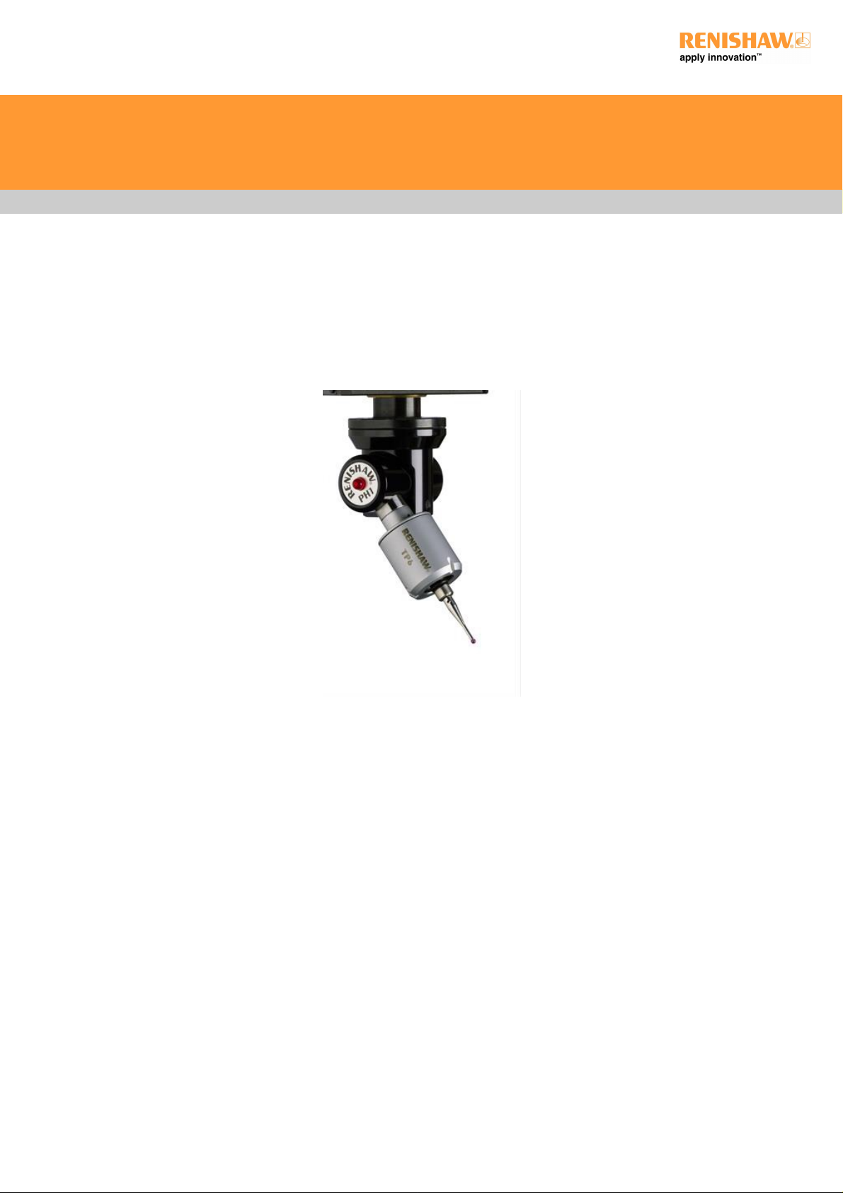
Probe system overview
In the context of this user's guide a probe system comprises a stylus mounted onto a touch-trigger probe that in turn is connected to a CMM
using a manual probe head.
The intention of this guide is to cover the most common combinations of the manual probe heads and touch-trigger probes in an attempt to
assist the user in making a product choice that is best for any particular application.
The guide covers the features of each of the standard kinematic touch-trigger probes and complementary manual probe heads.
Touch-trigger probe systems - TP1, TP2, TP6, TP6A, PH1, PH5, PH6, PH6M
http://www.renishaw.com
Issued 11 2014
6
Page 7
Probe product overview
Renishaw's CMM touch-trigger probes detailed in this user's guide are designed to suit any CMM, but their individual characteristics are
outlined below:
TP1(S) A robust shank-mounted probe offering generous overtravel - ideally suited to manual CMMs.
TP2 - 5-
way
A compact probe allowing component penetration - ideally suited to CNC / DCC machines.
TP6 Complementing the TP2 series, but carrying longer and heavier styli, this probe is suited to general-purpose applications.
TP6A This probe has all the functions of the TP6 probe and in addition the patented Renishaw autojoint that permits fast probe
exchange without the need to requalify.
Renishaw also manufacture other touch-trigger probes which are not detailed in the user's guide.
For details of these and other Renishaw products, visit the Renishaw website at www.renishaw.com.
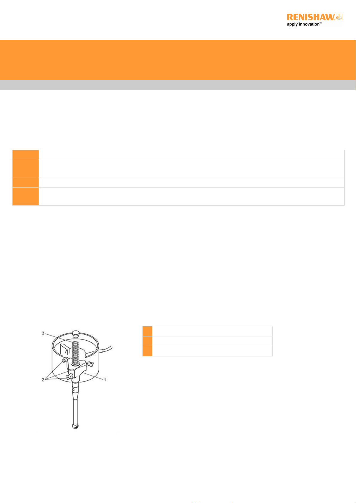
Principles of operation
The principle component of Renishaw touch-trigger probes is the kinematic location as shown below - a mechanical device that has the
ability to return the stylus ball to the same repeatable position following any deflection.
The kinematic location consists of a pivotal plate [1] that is spring-loaded against three bearing points [2] by a helical compression spring
[3]. These bearing points are formed by a combination of rollers and ball bearings.
Bearing points act as electrical contacts such that when the pivotal plate is deflected, the electrical circuit changes its characteristics and
causes the probe interface to send a trigger to the CMM controller.
Following this trigger event, the stylus ball must be removed from contact with the surface to enable the probe to return the stylus ball to its
repeatable position.
1 Pivotal plate
2 Three bearing points
3 Helical compression spring
Touch-trigger probe systems - TP1, TP2, TP6, TP6A, PH1, PH5, PH6, PH6M
http://www.renishaw.com
Issued 11 2014
7
Page 8
Probe description and operation
TP1(S) touch-trigger probe
The TP1(S) touch-trigger probe (illustrated below) is a robust shank-mounted probe with a generous overtravel which is especially suited to
manual CMMs. It is of a maintenance-free, sealed construction to provide a long working life.
The TP1(S) incorporates an M3 stylus mount which ensures compatibility with Renishaw's extensive M3 and M2 stylus and accessory range
using the appropriate stylus adaptor where necessary.
1 Shank
2 TP1(S) probe body
3 Trigger force adjustment screw
4 Probe cable (not supplied)
5 Stylus (not supplied)
6 2.5mm AF Allen key to adjust trigger force
7 S7 stylus tightening tool
8 Probe status LED
TP2-5-way touch-trigger probe
The TP2-5-way touch-trigger probe shown below is a compact (13 mm diameter) general-purpose probe suitable for use on all types of
CMM. It has an M8 mounting thread that ensures compatibility with Renishaw's comprehensive range of probe heads and extension bars.
The TP2 is of a maintenance-free construction to provide a long working life.
It incorporates an M2 stylus mount giving access to Renishaw's extensive M2 stylus range and accessories.
1 TP2 - 5-way probe
2 1.5mm AF Allen key to adjust trigger force
3 S7 stylus tightening tool
4 Stylus (not supplied)
Touch-trigger probe systems - TP1, TP2, TP6, TP6A, PH1, PH5, PH6, PH6M
http://www.renishaw.com
Issued 11 2014
8
Page 9
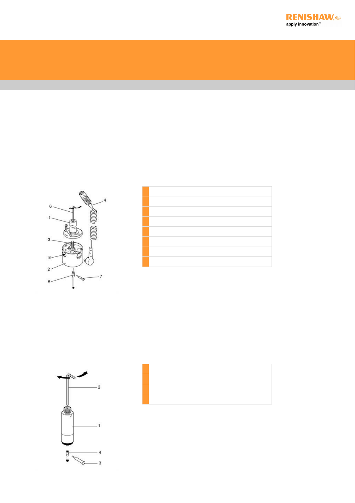
TP6 touch-trigger probe
The TP6 touch-trigger probe illustrated below combines the accuracy, flexibility and M8 mounting thread of the TP2-5-way probe with the
rugged construction and generous overtravel of the TP1(S).
The larger diameter of the TP6 (25 mm) allows the probe to carry longer and heavier styli configurations than the TP2-5-way, allowing it to
be used successfully on both universal DCC and manual CMMs.
It incorporates an M3 stylus mount which allows compatibility with Renishaw's extensive M3 and M2 stylus and accessory range using the
appropriate stylus adaptor where necessary.
1 TP6 probe
2 1.5mm AF Allen key to adjust trigger force
3 S7 stylus tightening tool
4 Stylus (not supplied)
Touch-trigger probe systems - TP1, TP2, TP6, TP6A, PH1, PH5, PH6, PH6M
http://www.renishaw.com
Issued 11 2014
9
Page 10
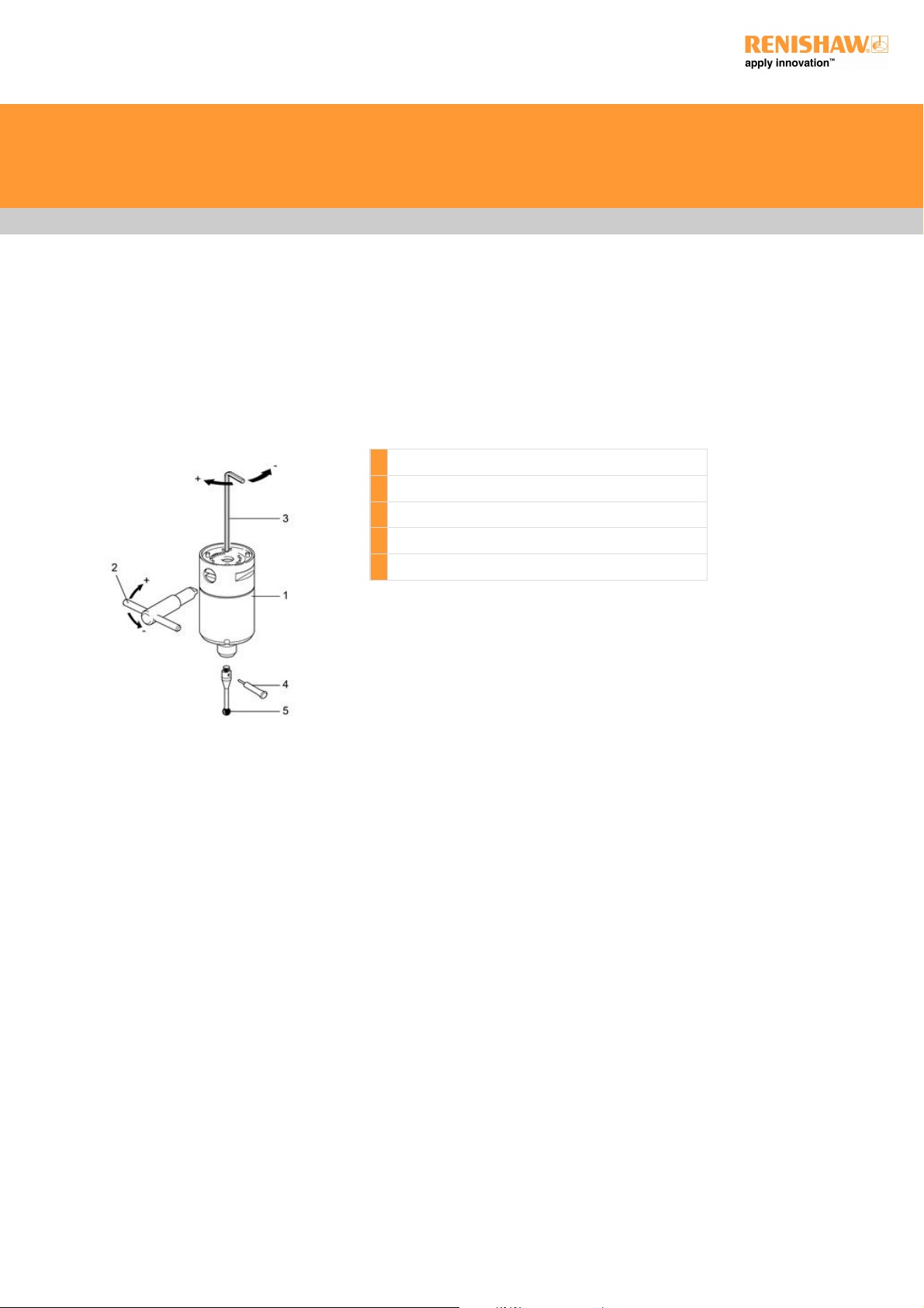
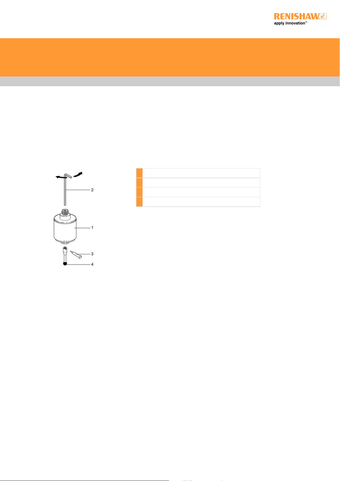
TP6A touch-trigger probe
The TP6A touch-trigger probe has all the features of the TP6 with the added benefit of the Renishaw autojoint. This is a highly repeatable
kinematic joint which allows rapid probe exchange without the need to requalify the probe tip. It can be operated either manually, using an
S10 autojoint key, or automatically, using the autochange rack system.
This probe can be used successfully on both universal DCC and manual CMMs. It incorporates an M3 stylus mount which offers
compatibility with all Renishaw's extensive M3 and M2 stylus and accessory range.
1 TP6A probe
2 S10 autojoint key
3 1.5mm AF Allen key to adjust trigger force
4 S7 stylus tightening tool
5 Stylus (not supplied)
Touch-trigger probe systems - TP1, TP2, TP6, TP6A, PH1, PH5, PH6, PH6M
http://www.renishaw.com
Issued 11 2014
10
Page 11

Installation
Electrical installation
TP1(S)
The 5-pin DIN socket on the TP1(S) probe provides the connections (shown below) to the probe interface.
Pin Function
1 LED cathode
2 Screen
3 LED anode
4 Probe circuit
5 Probe circuit
TP2 and TP6
Connections to the probe interface are made through the M8 mounting joint.
TP6A
Connections to the probe interface are made through the autojoint.
Fitting a stylus
To fit a stylus to a Renishaw touch-trigger probe, insert the correct threaded stylus or stylus adaptor into the stylus mount and tighten the
stylus securely using the S7 stylus tool provided.Tightening the stylus by any means other than the stylus tool provided (e.g. spanners, drill
bits,etc.) may cause internal damage to the probe mechanism.
NOTE: All stylus joints should be clean and free from dirt or debris.
Touch-trigger probe systems - TP1, TP2, TP6, TP6A, PH1, PH5, PH6, PH6M
http://www.renishaw.com
Issued 11 2014
11
Page 12

Applications guide
Stylus selection
In the majority of probing applications, to maximise accuracy we recommend that you:
Keep styli short and stiff
The more the stylus bends or deflects, the lower the accuracy. Probing with the minimum stylus length for your application is
recommended and where possible the use of one piece styli is suggested. Probing with excessive styli / extension combinations
should therefore be avoided.
Keep the stylus ball as large as possible
This will ensure maximum ball / stem clearance whilst providing a greater yet rigid effective working length (EWL). Using larger ruby
balls also reduces the effect of surface finish of the component being inspected.
EWL is the penetration that can be achieved by any ruby ball before its stem fouls against the feature. Generally, the larger the ball
diameter, the greater the EWL (see figure below).
A Overall working length
B EWL
C Ball / stem clearance
EWL can also be affected by assembly tolerances. For this reason, Renishaw styli are assembled to exacting standards in controlled
conditions.
Trigger force
Trigger force is the amount of pressure applied by the helical compression spring onto the pivotal plate and bearing points to hold the stylus
mount in place.
The trigger force is preset by Renishaw but can be altered for any of the following reasons:
to permit the use of longer styli on the probe
to permit the use of heavier styli on the probe
if the preset trigger force has decreased due to probe use
if the acceleration of the CMM is causing illegal triggers
NOTE: Changing the probe trigger force will affect the probe's measurement performance. It is important to requalify the probe
configuration and check the measurement performance of the probe system after any adjustment has been made to the trigger force.
Touch-trigger probe systems - TP1, TP2, TP6, TP6A, PH1, PH5, PH6, PH6M
http://www.renishaw.com
Issued 11 2014
12
Page 13

All Renishaw's touch-trigger probes have an optimum trigger force setting for general purpose applications as detailed in the table below.
Trigger force:
CMM probes Stylus length (typical) Optimum trigger force (preset by Renishaw) Trigger force range
TP1(S) 31 mm (PS1-1R) 0.15 N 0.1 N - 0.5 N
TP2-5 way 10 mm (PS12R) 0.07 N - 0.08 N 0.07 N - 0.15 N
TP6 / TP6A 21 mm (PS1-12R) 0.11 N - 0.13 N 0.11 N - 0.3 N
Checking trigger force with the Renishaw gram gauge
1. Ensure that the probe is held firmly in position (preferably on a CMM) and connected to an interface to detect a probe trigger.
2. Establish the direction of trigger which gives the minimum resistance. The most practical way of doing this is to gently deflect the stylus
with a finger, trying different directions. There are three lobes which produce three maximum and three minimum force directions. These can
easily be found with a minimum of practice.
3. Set the gram gauge maximum force indicator to the zero point and place the gram gauge flat on the CMM table. Move the stylus tip to the
same height above the surface as the gram gauge lever.
4. Slide the gram gauge slowly sideways so that the flat point on the end of the lever touches the probe stylus ball (ensuring that the probe is
deflected in the low force direction). Very slowly continue to move the gram gauge until the probe triggers, at which point stop immediately,
back off the gauge and read the maximum force indicator.
5. Repeat this procedure three or four times to ensure consistent results.
Touch-trigger probe systems - TP1, TP2, TP6, TP6A, PH1, PH5, PH6, PH6M
http://www.renishaw.com
Issued 11 2014
13
Page 14

NOTE: To convert gf to Newtons the following formula is required:
Newtons = gf / 100
Trigger force adjustment - TP1(S)
The trigger force of a TP1(S) probe is preset by Renishaw at an optimal performance setting, but can be altered if necessary as follows:
1. Remove the probe from the quill of your CMM.
2. Insert a 2.5 mm AF Allen key (supplied with every probe) into the centre of the shank until you locate a grub screw.
3. Adjust this grub screw to alter the trigger force of the probe:
Clockwise increases the trigger force
Anticlockwise decreases the trigger force
Trigger force adjustment - TP2 and TP6
The trigger force of TP2 and TP6 probes is preset by Renishaw at an optimal performance setting, but can be altered if necessary as
follows:
1. Remove the probe from the probe head on the quill of your CMM.
2. Insert a 1.5 mm AF Allen key (supplied with every probe) into the hole in the centre of the M8 thread until you locate a grub screw.
3. Adjust this grub screw to alter the trigger force of the probe:
Clockwise increases the trigger force
Anticlockwise decreases the trigger force
Trigger force adjustment - TP6A
The trigger force of a TP6A probe is preset by Renishaw at an optimal performance setting, but can be altered if necessary as follows:
1. Remove the probe from the probe head on the quill of your CMM.
2. Ensure that the cam of the autojoint is in the unlocked position.
3. Insert a 1.5 mm AF Allen key (supplied with every probe) through the cam towards the centre of the TP6A until you locate a grub screw.
4. Adjust this grub screw to alter the trigger force of the probe:
Clockwise increases the trigger force
Anticlockwise decreases the trigger force
Touch-trigger probe systems - TP1, TP2, TP6, TP6A, PH1, PH5, PH6, PH6M
http://www.renishaw.com
Issued 11 2014
14
Page 15

Manual probe heads product overview
Renishaw manual probe heads detailed in this user's guide are designed to suit any CMM and this specifically covers:
PH1 PH5 PH5/1 PH6 PH6M
Each is designed for a specific application and purpose. The figure below explains the product interconnections and both include the MH8
and MIH for completeness.
Probe head / touch-trigger probe compatibility:
Probe head Number of probes carried Orientation - A-axis Orientation - B-axis Orientation - Repeatable Probe joint
PH1 1 M8 bush
PH5 <5 (1*) M8 bush
PH5/1 <5 (1*) M8 bush
PH6 1 M8 bush
PH6M 1 Autojoint
MIH 1 Autojoint
MH8 1 M8 bush
Touch-trigger probe systems - TP1, TP2, TP6, TP6A, PH1, PH5, PH6, PH6M
http://www.renishaw.com
Issued 11 2014
15
Page 16

* This probe head can only connect one electronic probe (e.g. TP200).
Touch-trigger probe systems - TP1, TP2, TP6, TP6A, PH1, PH5, PH6, PH6M
http://www.renishaw.com
Issued 11 2014
16
Page 17

Manual probe heads description and operation
Renishaw manual probe heads provide the mechanical and electrical connections required when using the majority of Renishaw touchtrigger probes on a co-ordinate measuring machine (CMM).
Installed within the quill of the CMM via the shank supplied, a manual probe head permits a CMM touch-trigger probe to be held rigidly in
position. It also allows a touch-trigger probe to be connected to a Renishaw probe extension bar and probe knuckle joint for improved probe
orientation and component penetration (where indicated).
PH1 manual probe head
The PH1 is a general purpose, swivel-type probe head. Its compact design makes it ideally suited to a CMM where manual orientation of a
Renishaw M8 touch-trigger probe is required.
The PH1 provides two axes of movement. The A-axis allows probe orientation in the vertical plane; the B-axis allows rotational probe
orientation. Axis rotation is in relation to the shank mount.
The PH1 manual probe head incorporates the following primary components and is supplied with the following tools:
PH1 probe head [1]
Probe cable (to probe interface) [2]
Shank [3]
2.5 mm AF Allen key [4] (for tightening the shank socket screws)
2 mm AF Allen key [5] (for adjusting the B-axis locking force)
Probe status LED [6]
3 mm AF Allen key [7] (for adjusting the A-axis orientation)
1 PH1 probe head
2 Probe cable (not supplied)
3 Shank
4 2.5 mm AF Allen key
5 2 mm AF Allen key
6 Probe status LED
7 3 mm AF Allen key
8 TP2 5-way touch-trigger probe (not supplied)
9 B-axis force adjustment screw
TheAaxismaybeswivelledthrough±115°andlockedinpositionusingthe3mmAFAllenkey[7]supplied.Forinstructionsonhowto
move and lock the A-axis, see 'Moving and locking the A-axis'.
TheBaxisisindexable,in15°steps,through360°.ForinstructionsonhowtomoveandlocktheBaxis,see'MovingandlockingtheB
axis'.
Connection of the PH1 to the CMM is via the probe cable [2] and an appropriate probe interface (not supplied).
The status of the probe is indicated by the probe status LED [6]. This is normally lit when the probe is ready for use and extinguishes as the
probe triggers.
Touch-trigger probe systems - TP1, TP2, TP6, TP6A, PH1, PH5, PH6, PH6M
http://www.renishaw.com
Issued 11 2014
17
Page 18

Technical data - PH1
Number of sockets One
Style of probe joint M8 bush
Probe status indication One LED located on the A-axis swivel
Cable connection Renishaw standard 5-pin DIN 180 socket
Overtravel break load Adjustable from 0.02 kgf (0.44 lbf) to locked solid
A-axis indexing ±115°
B-axis indexing 15°stepsthrough360°
Weight (excluding shank) 125 g (0.28 lb)
Installing and connecting the PH1
ForinstructionsonhowtoinstallandconnectthePH1,see“Installingamanualprobehead”.
Moving and locking the A-axis
TheAaxismaybeswivelledthrough±115°andlockedinanyposition,asdescribedbelow:
1. Insert the 3 mm AF Allen key [2] (supplied) into the Allen cap-head screw [1] located within the B-axis body.
2. Rotate the Allen key [2] in the counter-clockwise direction to release the holding pressure on the A-axis [3].
3. Swivel the A-axis [3] into the required position.
4. Hold the A-axis [3] in this position, and reassert the holding pressure on the A-axis by rotating the Allen key [2] in the clockwise direction.
1 Cap-head screw
2 3 mm AF Allen key
3 A-axis
Touch-trigger probe systems - TP1, TP2, TP6, TP6A, PH1, PH5, PH6, PH6M
http://www.renishaw.com
Issued 11 2014
18
Page 19

Moving and locking the B-axis
The B-axis locking force of the PH1 can be adjusted so that no B-axis rotation is possible. If the PH1 will not index by hand, the locking force
must be decreased.
To decrease the locking force, see 'Locking the B-axis'.
Moving the B-axis
TheBaxisofthePH1canbeindexedin15°incrementsthroughoutthe360°axisofrotation.Dothisasdescribedbelow:
1. Hold the A-axis of the PH1.
2. Rotate the B-axis of the probe to the required step.
3. Release the A-axis.
Locking the B-axis
Adjust the holding force of the B-axis as described below:
1. With the PH1 removed from the quill of the CMM, insert the 2.5 mm AF Allen key [1] into the centre of the shank [2] until it locates the
head of the B-axis force adjustment screw [3].
2. Adjust the B-axis force adjustment screw [3] as follows:
Rotate clockwise to increase the holding force
Rotate counter-clockwise to decrease the holding force
1 2.5 mm AF Allen key
2 Shank
3 B-axis force adjustment screw
PH5 manual probe head
The PH5 is a compact probe head that is capable of carrying up to five TP2 or TP6 touch-trigger probes simultaneously, or one TP200
strain gauge probe.
The PH5 incorporates the following primary components and is supplied with the following tools:
PH5 probe head [1]
2.5 mm AF Allen key [2] (for tightening shank socket screws)
Shank [3]
Two probe status LEDs [5]
Five socket covers [6]
Five insulating washers [7]
Touch-trigger probe systems - TP1, TP2, TP6, TP6A, PH1, PH5, PH6, PH6M
http://www.renishaw.com
Issued 11 2014
19
Page 20

The status of the probe is indicated by the probe status LEDs [5]. These are normally lit when the probe is ready for use and extinguish as
the probe triggers.
Technical data - PH5
Number of sockets Five
Style of probe joint M8 bush
Probe status indication Two LEDs
Electrical connection Standard Renishaw 5-pin DIN socket
Weight (excluding shank) 184 g (0.41 lb)
Installing and connecting the PH5
For instructions on how to install and connect the PH5, see 'Installing a manual probe head'.
1 PH5 probe head
2 2.5mm AF Allen key
3 Shank
4 Probe cable (not supplied)
5 Probe status LED (2 off)
6 Socket cover (5 off)
7 Insulating washer (5 off)
8 TP2-5 way touch-trigger probe (not supplied)
NOTE: The PH5 probe head contains five M8 probe sockets. Each socket that does not contain a probe must be fitted with a socket
cover [6] and insulating washer [7].
PH5/1 manual probe head
The PH5/1 probe head is similar to the PH5 model. It is a compact unit that is capable of carrying up to five TP2 or TP6 touch-trigger
probes simultaneously, or one TP200 strain gauge probe.
It offers the additional features of positive indexing in the B-axis and limited overtravel protection.
The PH5/1 incorporates the following primary components and is supplied with the following tools:
PH5/1 probe head [1]
Overtravel/B-axis orientation unit [2]
2.5mm AF Allen key [3] (for tightening shank socket screws)
Shank [4] LEDs [6]
Five socket covers [7]
Five insulating washers [8]
Touch-trigger probe systems - TP1, TP2, TP6, TP6A, PH1, PH5, PH6, PH6M
http://www.renishaw.com
Issued 11 2014
20
Page 21

The status of the probe is indicated by the probe status LEDs [6]. These are normally lit when the probe is ready for use and extinguish as
the probe triggers.
NOTE: The PH5/1 probe head contains five M8 probe sockets. Each socket that does not contain a probe must be fitted with a
socket cover [7] and insulating washer [8].
1 PH5/1 probe head
2 Overtravel / B-axis orientation unit
3 2.5mm AF Allen key
4 Shank
5 Probe cable (not supplied)
6 Probe status LED (2 off)
7 Socket cover (5 off)
8 Insulating washer (5 off)
9 TP2 5-way touch-trigger probe (not supplied)
Technical data - PH5/1
Number of sockets Five
Style of probe joint M8 bush
Probe status indication Two LEDs
Cable connection Renishaw standard 5-pin DIN socket
Overtravel break load Adjustable from 0.02 kgf (0.44 lbf) to locked solid
A-axis indexing Not applicable
B-axis indexing 15 steps through 360
Weight (excluding shank) 290 g (0.64 lb)
Installing and connecting the PH5/1
For instructions on how to install and connect the PH5/1, see 'Installing a manual probe head'.
Moving and locking the B-axis
The B-axis locking force of the PH5/1 can be adjusted so that no B-axis rotation is possible. If the PH5/1 will not index by hand, then the
locking force must be decreased.
To decrease the locking force, see 'Locking the B-axis'.
Moving the B-axis
TheBaxisofthePH5/1canbeindexedin15°incrementsthroughoutthe360°axisofrotation.
NOTE: If the main body of the PH5/1 remains locked, see 'Locking the B-axis'.
1. Hold the overtravel / B-axis orientation unit [2].
2. Rotate the probe head [1] to the required step.
Touch-trigger probe systems - TP1, TP2, TP6, TP6A, PH1, PH5, PH6, PH6M
http://www.renishaw.com
Issued 11 2014
21
Page 22

3. Release the overtravel / B-axis orientation unit [2].
Locking the B-axis
Adjust the locking force of the B-axis as described below:
1. Hold the knurled section of the overtravel / B-axis orientation unit [2].
2. Rotate the overtravel / B-axis orientation unit [2] to alter the locking force as follows:
Rotate clockwise to increase the holding force
Rotate counter-clockwise to decrease the holding force
3. Release the overtravel / B-axis orientation unit [2].
1 Probe head
2 Overtravel / B-axis orientation unit
PH6 manual probe head
The PH6 is a compact, vertically mounted probe head that is ideally suited to a manual CMM where a single probe is required. It can be
used with TP2, TP6, and TP20 touch-trigger probes.
The PH6 incorporates the following primary components:
PH6 probe head / shank assembly with integral cable [1]
Probe status LED [2]
The status of the probe is indicated by the probe status LED [2] that is located within the body of the probe head. During normal operation,
the LED indicates the probe status as follows:
LED illuminated: Probe is seated and is ready for use.
LED extinguished: Probe has triggered / no probe is fitted.
1 PH6 probe head, shank and integral cable
2 Probe status LED
3 Touch-trigger probe (not supplied)
Touch-trigger probe systems - TP1, TP2, TP6, TP6A, PH1, PH5, PH6, PH6M
http://www.renishaw.com
Issued 11 2014
22
Page 23

Technical data - PH6
Number of sockets One
Style of probe joint M8 bush
Probe status indication One LED
Cable connection Dedicated integral cable
Weight (excluding shank) 48g (0.11 lb)
Installing and connecting the PH6
For instructions on how to install and connect the PH6, see 'Installing a manual probe head'.
The PH6 is fitted with an integral cable, connector, and shank. These cannot be changed.
PH6M manual probe head
The PH6M is a fixed probe head that incorporates the Renishaw autojoint [6]. It has the ability to convey complex probe signals via its 15-
waymicro‘D'connector,thuspermittingtheuseoftheRenishawTP7highaccuracytouchtriggerprobeandOPT6Mopticaltouchtrigger
probe.
The PH6M incorporates the following primary components and is supplied with the following tools:
PH6M probe head [1]
2.5 mm AF Allen key [2] (for tightening shank socket screws)
Shank [3]
Probe status LED [5]
Autojoint adaptor [6]
S10 joint key [7]
1 PH6M probe head
2 2.5mm AF Allen key
3 Shank
4 Multiwired probe cable (not supplied)
5 Probe status LED
6 Autojoint adapter (not supplied)
7 S10 joint key
Touch-trigger probe systems - TP1, TP2, TP6, TP6A, PH1, PH5, PH6, PH6M
http://www.renishaw.com
Issued 11 2014
23
Page 24

The probe head can be used with all Renishaw standard CMM touch-trigger probes and accessories. It can also be used with the PAA
adaptor and M8 extension bars.
Locking and unlocking the autojoint is performed either manually using the S10 joint key [7] supplied, or automatically using the Renishaw
autochange system. This allows probes to be changed without the need to requalify.
The status of the probe is indicated by the probe status LED [5]. This is normally lit when the probe is ready for use and extinguishes as the
probe triggers.
Technical data - PH6M
Number of sockets One
Style of probe joint Multiwired autojoint
Probe status indication One LED
Cable connection 15-way micro D' connector
Autojoint repeatability (2s) 1m (0.00004in.) using a TP6A touch-trigger probe and 21mm stylus
Weight 160g (0.36lb)
Installing and connecting the PH6M
For instructions on how to install and connect the PH6M, see 'Installing a manual probe head'.
ThePH6Misfittedwithanintegral15pinmicro‘D'socket.Ifrequired,thissocketcanbeadaptedbyusingasuitablecabletowhicha5pin
DIN socket has been fitted.
Touch-trigger probe systems - TP1, TP2, TP6, TP6A, PH1, PH5, PH6, PH6M
http://www.renishaw.com
Issued 11 2014
24
Page 25

Installing a manual probe head
Fitting an M8-threaded CMM touch-trigger probe to a manual probe head
Fit an M8-threaded non-autojointed CMM touch-trigger probe to a manual probe head as described below:
NOTE: The PH5 and PH5/1 probe heads contain five M8 probe sockets. Each socket that does not contain a probe must be fitted
with a socket cover and insulating washer.
1. By hand, screw the threaded end of the touch-trigger probe into the M8 bush of the manual probe head and hand-tighten to secure.
2. FittheS1‘C'spanner(supplied)tothetouchtriggerprobeasshownbelow.
3. Use the spanner to tighten the touch-trigger probe into the M8 bush.
The S1 C' spanner is designed to break before any damage can occur to either the probe or the probe head due to over-tightening
the probe.
Do not use any other tool to tighten the probe in the probe head as this could result in damage to both the probe and the probe head.
Fitting an autojointed CMM touch-trigger probe to a manual probe head
The repeatability of the Renishaw autojoint ensures that a probe need only be qualified once. The qualification data can then be recalled
whenever the probe is re-attached.
Fit an autojointed CMM touch-trigger probe or PAA series adaptor to a manual probe head as described below:
1. Check that the locking cam on the autojointed probe is in the unlocked position (the slot is horizontal).
2. Offer up the autojointed probe to the PH6M, ensuring that the alignment marks on both the probe and the probe head are correctly
aligned.
NOTE: If the TP6A touch-trigger probe is to be used in conjunction with the Renishaw autochange system, the TP6A should be
lockedtotheprobeheadbyrotatingthecamfullyclockwiseandthenreversingitby5°.
3.InserttheS10jointkeyintothecamoftheautojointedprobeandrotateclockwise(120°)tolocktheprobetotheprobehead.
Touch-trigger probe systems - TP1, TP2, TP6, TP6A, PH1, PH5, PH6, PH6M
http://www.renishaw.com
Issued 11 2014
25
Page 26

Attaching a shank to a manual probe head (except PH6)
Renishaw products may incorporate either three or four tapped holes to facilitate fitting a shank. Renishaw shanks are supplied with five
holes to allow either three-hole or four-hole products to be fitted to them.
Attach a Renishaw shank to a Renishaw manual probe head as described below:
1. Locate the shank on to the top of the probe head.
2. Align the holes within the shank with those within the probe head.
3. InsertanM3×6mmAllencapscrewintoeachofthethreeorfourtappedholesandhandtightenusingthe2.5mmAllenkeysupplied.
1 2.5 mm AF Allen key
2 M3×6mmAllencapscrew
The pin configuration and outputs are detailed below.
The PH6 has an integral cable and connector. This will conform to the CMM manufacturer's specification. If the connector on the attached
cable has a 5-pin DIN connection then, subject to external verification, the cable pin outputs will be as specified below.
ThePH6Misfittedwithanintegral15pinmicro‘D'socket.Ifrequired,thissocketcanbeadaptedbyusingasuitablecabletowhicha5pin
DIN socket has been fitted.
Touch-trigger probe systems - TP1, TP2, TP6, TP6A, PH1, PH5, PH6, PH6M
http://www.renishaw.com
Issued 11 2014
26
Page 27

Pin Function Wire colour
1 LED cathode Red
2 Screen Screen
3 LED anode Yellow
4 Probe circuit Blue
5 Probe circuit Green
Connecting a manual probe head electrically to a CMM
All Renishaw manual probe heads (except the PH6 and PH6M) have an integral 5-pin DIN female connector. This connector is compatible
with the Renishaw moulded 5-pin plug that is fitted to all Renishaw manual probe head cables.
Touch-trigger probe systems - TP1, TP2, TP6, TP6A, PH1, PH5, PH6, PH6M
http://www.renishaw.com
Issued 11 2014
27
Page 28

Maintenance - cleaning
Renishaw manual heads and touch-trigger probes are sealed, maintenance-free products. They may be wiped with a clean, dry, lint-free
cloth. The units are not sealed against water.
Touch-trigger probe systems - TP1, TP2, TP6, TP6A, PH1, PH5, PH6, PH6M
http://www.renishaw.com
Issued 11 2014
28
Page 29

Accessories
Please contact your Renishaw representative for further information on any of the accessories described in this section or for details of
Renishaw's extensive range of innovative products for CMMs, machine tools, digitising, accuracy checking, calibration, scale systems and
spectral analysis.
Styli
Renishaw manufacture an extensive range of precision styli and stylus accessories.
The Renishaw stylus range can be used with any probe covered in this guide and offers a variety of ball sizes in industrial ruby from 0.3 mm
(0.012 in) to 8 mm (0.31 in) diameter. These are available with steel, tungsten carbide, ceramic and Renishaw graphite fibre (GF) stems to
cover a wide range of applications.
Specialist application styli including discs, cylinders, pointers, stars and large ceramic balls - up to 30 mm (1.18 in) diameter - are available.
Renishaw also offer a custom design service if your requirements are not met by our standard range. Please contact your Renishaw
representative for details.
ForfurtherinformationontheRenishawstylusrange,pleaserefertothe‘Styliandaccessoriestechnicalspecifications'(Renishawpart
number H-1000-3200).
Touch-trigger probe systems - TP1, TP2, TP6, TP6A, PH1, PH5, PH6, PH6M
http://www.renishaw.com
Issued 11 2014
29
Page 30

Troubleshooting
If you experience problems which you are unable to identify or solve satisfactorily, please contact your Renishaw representative for further
advice or contact the Technical Support Department at any Renishaw office for free assistance by telephone (see address list on rear
cover).
Poor measurement performance:
Possible cause Solution
Probe or probe extension bar not installed correctly. Remove probe and / or probe extension bar and re-fit using the S1 spanner.
Stylus configuration too long or not rigid. Use shorter / stiffer stylus configuration.
Poor stylus assembly. Ensure that the number of stylus joints is kept to a minimum and all joints are clean
and secure.
Contaminated / damaged stylus ball. Inspect for damage, clean thoroughly with solvent.
Trigger force too high. Decrease trigger force to the minimum necessary to ensure reliable triggering.
Too few points taken for probe qualification /
measurement.
Take a larger number of points on the qualification / feature measurement.
Unwanted triggers during CMM movement:
Possible cause Solution
Trigger force set too low. Increase trigger force to the minimum necessary to ensure reliable triggering.
Stylus configuration too heavy. Reduce mass of stylus configuration.
Reduce stylus length to minimum possible.
Use a lightweight material for stylus configuration (GF or ceramic).
No probe signal:
Possible cause Solution
Probe not installed correctly. Remove probe and re-fit using the S1 spanner.
Probe extension bar failure. Check connections and integrity of probe extension bar.
Contact your CMM supplier or Renishaw representative for further assistance.
Probe failure. Contact your CMM supplier or Renishaw representative for further assistance.
Touch-trigger probe systems - TP1, TP2, TP6, TP6A, PH1, PH5, PH6, PH6M
http://www.renishaw.com
Issued 11 2014
30
Page 31

Probe fails to re-arm after trigger:
Possible cause Solution
Trigger force set too low. Increase trigger force to the minimum necessary to ensure reliable triggering.
Stylus configuration too
heavy.
Reduce mass of stylus configuration.
Reduce stylus length to minimum possible.
Use a lightweight material for stylus configuration (GF or ceramic).
Probe reseat failure. Retrigger probe. Many DCC CMMs will attempt to do this automatically (refer to your CMM supplier for
details).
If this problem persists, please return the probe to your Renishaw representative for service.
Touch-trigger probe systems - TP1, TP2, TP6, TP6A, PH1, PH5, PH6, PH6M
http://www.renishaw.com
Issued 11 2014
31
Page 32

Technical product specifications
TP1(S) TP2-5 way TP6 / TP6A
Sense directions X, Y, +Z X, Y, +Z X, Y, +Z
Uni-directional
repeatability
(max2σatstylustip)
0.5µm
(0.00002 in)
0.35µm
(0.000014 in)
0.35µm
(0.000014 in)
Pre-travel variation over
360°
(XY plane)
±2µm
(±0.00008in)
±0.8µm
(±0.000032in)
±0.6µm
(±0.000024in)
Trigger force range
(adjustable)
10 g - 50 g
(0.35 oz - 1.76 oz)
7 g - 15 g
(0.25 oz - 0.53 oz)
11 g - 30 g
(0.39 oz - 1.06 oz)
Trigger force (set by
Renishaw)
15 g
(0.53 oz)
7 g - 8 g
(0.25 oz - 0.28 oz)
11 g - 13 g
(0.39 oz - 0.46 oz)
Stylus overtravel: XY axis ±19.5° ±14° ±22°
Stylus overtravel: +Z axis 8.5 mm (0.33 in) @ 10 g (0.35 oz)
trigger force
4 mm (0.16 in) @ 7 g (0.25 oz)
trigger force
5.5 mm (0.22 in) @ 11 g (0.39 oz)
trigger force
Stylus overtravel: -Z axis n/a n/a n/a
Test conditions: Trigger
force
15 g
(0.53 oz)
7 g - 8 g
(0.25 oz - 0.28 oz)
11 g - 13 g
(0.39 oz - 0.46 oz)
Test conditions: Trigger
speed
8 mm (0.32 in) / sec 8 mm (0.32 in) / sec 8 mm (0.32 in) / sec
Test conditions: Stylus
used
PS1-1R PS12R PS1-12R
Test conditions: Stylus
length
31 mm (1.22 in) 10 mm (0.39 in) 21 mm (0.83 in)
Touch-trigger probe systems - TP1, TP2, TP6, TP6A, PH1, PH5, PH6, PH6M
http://www.renishaw.com
Issued 11 2014
32
Page 33

For worldwide contact details,
please visit our main website at
www.renishaw.com/contact
Renishaw plc
New Mills, Wotton-under-Edge,
Gloucestershire, GL12 8JR
United Kingdom
T +44 (0)1453 524524
F +44 (0)1453 524901
www.renishaw.com/cmmsupport
Issued 11 2014
 Loading...