

Renishaw TONiC FS T301 Series, TONiC RELM20, TONiC RSLM20, TONiC FS T3 Series, TONiC FS T303 Series Functional Safety Manual
...
Installation guide
M-6688-9046-02-B
TONiC™ FS T301x RSLM20 / RELM20 high accuracy linear encoder system
Functional Safety installation guide and safety manual

Contents
Product compliance 1
Denitions 2
Information for use 2
Functional Safety data declaration 2
Safety function 3
Certication 4
Storage and handling 5
TONiC FS T301x readhead installation drawing 6
Measuring lengths 7
Scale installation drawing 8
Readheadmountingandalignment 14
System calibration 15
Diagnostic LEDs 16
Output signals 17
Speed 18
Electrical connections 19
Outputspecications 20
Generalspecications 21
RSLM20scaletechnicalspecications 22
RELM20scaletechnicalspecications 22
Scale installation 9
Reference mark selector and limit magnet installation 10
TONiC FS quick-start guide 11
Cable connection 12
System connection – Ti interface 12
System connection – DOP interface 13
TONiC RSLM20/RELM20 Functional Safety installation guide and safety manual Original instructions
Reference mark 22
Limit switches 22
TONiC Ti interface drawing 23
TONiC DOP interface drawing 23

Product compliance
This document is an installation guide and safety manual, which details the actions required for the safe
integration of the TONiC FS (Functional Safety) encoder system, as designated by the T3 prex in the part
number, into a functionally safe system; this will be referred to as TONiC FS system in the below document.
SIL2
FUNCTIONAL
SAFETY
PLd
The TONiC FS system as dened below is suitable for use in a Category 3 performance leveld(PLd)
application in compliance with ISO 13849 and in a safety integrity level 2 (SIL2) application in compliance
with IEC61508 and IEC61800-5-2 when installed and operated in accordance with the instructions dened.
Failure to follow the correct use instructions or heed the limitations may result in SIL2 and/or PLd
notbeingachievedandwillinvalidatetheFunctionalSafetycertication.
A copy of the TONiC FS certicate is available from our website at www.renishaw.com/productcompliance
C
Renishaw plc declares that TONiC FS system complies with the applicable standards and regulations.
A copy of the EU declaration of conformity is available from our website at
www.renishaw.com/productcompliance.
For further details of FS compliance see ‘Certication’ on page 4.
FCC compliance
This device complies with part 15 of the FCC Rules. Operation is subject to the following two conditions:
(1) This device may not cause harmful interference, and (2) this device must accept any interference
received, including interference that may cause undesired operation.
The user is cautioned that any changes or modications not expressly approved by Renishaw plc or
authorised representative could void the user’s authority to operate the equipment.
This equipment has been tested and found to comply with the limits for a Class A digital device, pursuant
to part 15 of the FCC Rules. These limits are designed to provide reasonable protection against harmful
interference when the equipment is operated in a commercial environment. This equipment generates, uses,
and can radiate radio frequency energy and, if not installed and used in accordance with the instruction
manual, may cause harmful interference to radio communications. Operation of this equipment in a
residential area is likely to cause harmful interference in which case the user will be required to correct the
interference at their own expense.
NOTE: This unit was tested with shielded cables on the peripheral devices. Shielded cables must be used
with the unit to ensure compliance.
Patents
Features of Renishaw’s encoder systems and similar products are the subjects of the following patents and
patent applications:
EP1173731 US6775008B2 JP4750998 CNCN100543424C US7659992
EP1766334 JP4932706 CNCN100507454C US7550710 JP5386081
EP1766335 CNCN101300463B EP1946048 US7624513B2 JP5017275
CNCN101310165B US7839296 EP1957943 CN1314511 EP1469969
JP5002559 US8987633 US8466943
Disclaimer
RENISHAW HAS MADE CONSIDERABLE EFFORTS TO ENSURE THE CONTENT OF THIS DOCUMENT
IS CORRECT AT THE DATE OF PUBLICATION BUT MAKES NO WARRANTIES OR REPRESENTATIONS
REGARDING THE CONTENT. RENISHAW EXCLUDES LIABILITY, HOWSOEVER ARISING, FOR ANY
INACCURACIES IN THIS DOCUMENT.
The packaging of our products contains the following materials and can be recycled.
Packaging Component Material ISO11469 Recycling Guidance
Outer box Cardboard Not applicable Recyclable
Polypropylene PP Recyclable
Inserts Low Density Polyethylene Foam LDPE Recyclable
Cardboard Not applicable Recyclable
Bags High Density Polyethylene Bag HDPE Recyclable
Metalised Polyethylene PE Recyclable
REACH regulation
Information required by Article 33(1) of Regulation (EC) No. 1907/2006 (‘REACH’) relating to products
containing substances of very high concern (SVHCs) is available at www.renishaw.com/REACH
Further information
Further information relating to the TONiC FS encoder range can be found at
www.renishaw.com/fsencoders and is also available from your local representative. This document may
not be copied or reproduced in whole or in part, or transferred to any other media or language, by any
means without the written prior permission of Renishaw. The publication of material within this document
does not imply freedom from the patent rights of Renishaw plc.
The use of this symbol on Renishaw products and/or accompanying documentation indicates that the
product should not be mixed with general household waste upon disposal. It is the responsibility of the end
user to dispose of this product at a designated collection point for waste electrical and electronic equipment
(WEEE) to enable reuse or recycling. Correct disposal of this product will help to save valuable resources
and prevent potential negative effects on the environment. For more information, please contact your local
waste disposal service or Renishaw distributor.
1TONiC RSLM20/RELM20 Functional Safety installation guide and safety manual Original instructions
Denitions
Functional Safety data declaration
WARNING A hazard with a medium risk of injury if not avoided
ESD handling
Mechanical safe position
Evaluation unit
System manufacturer
System installer
Information for use
The ESD Susceptibility Symbol consists of a triangle, a reaching hand, and a slash
through the reaching hand. The triangle means ‘Caution’ and the slash through the
reaching hand means ‘Don’t touch’.
The maximum distance the scale might move from its installed position, for example if
the xings work loose.
External item of equipment in which the output signal of the encoder is evaluated,
e.g. machine controller or safety relay.
Personnel with responsibility for selecting the encoder and verifying its capability is
appropriate for the safety related application.
Personnel with responsibility for tting the encoder in the specic application.
WARNING Not to be used in environments where there is an explosive atmosphere
WARNING Not to be used by medical devices
The TONiC FS system is designed to be used as part of a safety-related control system as specied by the system
manufacturer. It is the responsibility of the system manufacturer to set the evaluation unit to implement the appropriate
actions when the TONiC FS system reports an error. The decision to use this system for the intended purpose is the
responsibility of the system manufacturer. The TONiC FS system is certied to the SIL and PL levels as shown in the
‘Functional Safety data declaration’, however the system manufacturer must conduct their own assessment of the full
system to determine its safety capability.
Correct use includes:
X Operating the TONiC FS system within the limits dened in this document.
X Installing the system as described in this document.
X Maintaining the system as described in this document.
System components:
The TONiC FS system comprises the following parts:
X TONiC FS readhead.
X TONiC Ti0000A00A or DOP interface.
X RSLM and RELM linear scale – adhesive mount only.
NOTES:
X Clip mounting RELM/RSLM linear scale is not approved for use with the TONiC FS encoder system.
X Only the analogue sine and cosine outputs are functionally safe.
If the original termination supplied with the TONiC FS system is altered or an extension cable used, then it is the
responsibility of the system manufacturer to make sure the system is compliant with IEC 61800-5-2 Annex E
–Electromagneticimmunityrequirementforsafetyrelatedsystems.
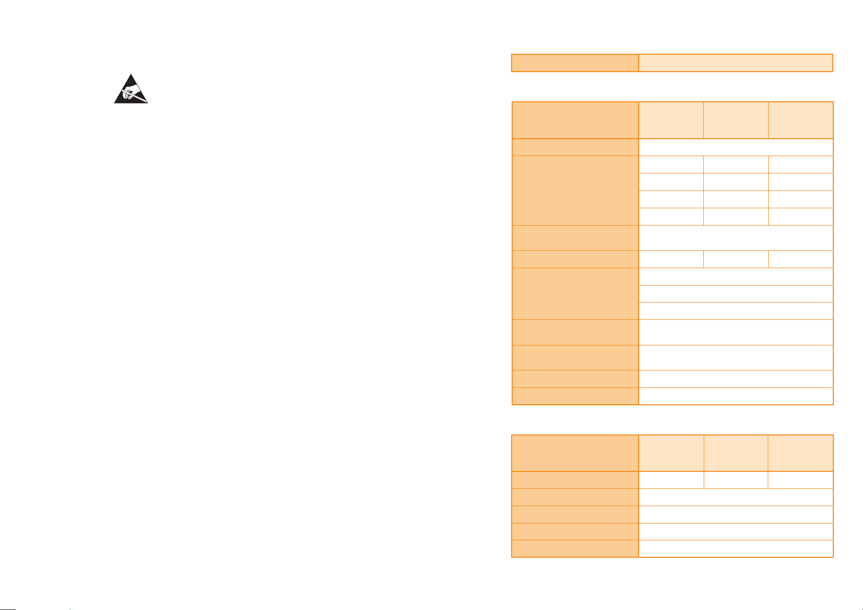
Productidentication TONiC FS (Functional Safety)
IEC61508safetydata
TONiC
readhead
Safety integrity level 2
Random hardware
failures (per hour)
PFD
avg
l
l
l
l
1.77 × 10
S
8.41 ×10
D
7.57 × 10
DD
8.41 × 10
DU
Not available as this system does not support low
PFH (per hour) 8.41 × 10
Architectural
constraints
Type B
HFT 0
−7
−8
−8
−9
−9
SFF 96%
Hardware safety integrity
compliance
Systematic safety integrity
compliance
Systematic capability SC 2
Demand mode Continuous
TONiC
readhead and
Ti interface
1.77 × 10
1.38 × 10
1.25 × 10
1.38 × 10
demand mode
1.38 × 10
Route 1H
Route 1S
ISO13849safetydata
TONiC
readhead
MTTF
(years) 1300 800 300
D
Diagnostic coverage Medium (90%)
Category 3
Performance level d
Lifetime/replacement limits 20
TONiC
readhead and
Ti interface
−7
−7
−7
−8
−8
TONiC
readhead and
DOP interface
1.77 × 10
3.49 × 10
3.14 × 10
3.49 × 10
3.49 × 10
−7
−7
−7
−8
−8
TONiC
readhead and
DOP interface
2TONiC RSLM20/RELM20 Functional Safety installation guide and safety manual Original instructions

Safety function
The TONiC FS system provides 1 Vpp (nominal) sine and cosine outputs, where the sine and cosine
outputs are 90° phase shifted, in order for the evaluation unit to perform incremental counting and
therebyconrmmachinepositioniswithinsafelimits.
The following restrictions apply to this claim:
X The system installer must perform a veried commissioning test during installation.
X The system repairer must perform a veried commissioning test following replacement of a system part.
X When installed correctly, the TONiC FS system shall have mechanical safe position not exceeding 1 mm.
NOTE: Thermal expansion effects of the scale and readhead mounting tolerances are excluded from the
mechanical safe position.
X The TONiC FS system includes no self-diagnostic function.
NOTE: Faults are detected only by the evaluation unit monitoring. When errors are detected it is the
responsibility of the system manufacturer to place the system into a safe state.
Fault exclusions
The following will invalidate the Functional Safety certication of the TONiC FS system (see page 4):
X Faults caused by cutting and reconnecting the readhead cable or extending the readhead cable.
X Incorrect installation of the readhead.
X Incorrect installation of the scale.
X Dismantling of the TONiC readhead or the Ti or DOP interfaces.
X Operating the system outside of the limits specied within this installation guide.
Failure modes
Failure modes are detected by evaluation unit monitoring. See ‘Functional Safety data declaration’ on page 2
for a summary of the FMEDA.
NOTE: For the purposes of the FMEDA calculation, the following conditions have been assumed:
Method: SN29500 Environment: Ground mobile Temperature: 85°C
Installation
For the safety function to be valid the instructions detailed in this installation guide must be followed.
Commissioning test
The following check must be performed when commissioning the TONiC FS system and after any repair of
the system.
NOTE: Repair is by replacement of system parts only.
Axis movement check Move the axis over its full travel to verify the following:
X Position output is correct within a tolerance of ±10%.
X Direction of movement is correct.
X The signal amplitude for both sine and cosine signals falls within the limits
dened in ‘Evaluation unit monitoring’.
Evaluation unit monitoring
To achieve full system integrity the evaluation unit must continuously monitor the analogue outputs and,
in the case of fault detection, place the system into a safe state within the process safety time.
Signal amplitude check Nominal signal amplitude value is 1V, indicating full signal strength where
√ (sine2 + cosine2) = 1V. A fault condition must be asserted if the analogue
output is ≤0.7 V and ≥1.35 V.
Sine/cosine cross
check
Following error check Following error is dened as the difference between the expected position
NOTES:
X The evaluation unit must achieve medium diagnostic coverage (≥90%) according to ISO13849.
X Improper setting of the switching thresholds and hysteresis in signal evaluation can result in incorrect
determination of direction, position or speed.
X A persistent fault condition may indicate a hardware failure of the TONiC FS system or an
installation problem.
Sine and cosine signals must be evaluated separately and the results
compared. A fault condition must be asserted if the phase shift is incorrect with
reference to the safe position limit for the system, see ‘Output specications’ on
page 20.
and position feedback. A fault condition must be asserted if the following error
exceeds the safe position limit for the system.
Maintenance
The maintenance check intervals will be dened by the system manufacturer according to their risk
assessment. There are no user serviceable parts within the readhead and interface.
The following maintenance actions are advised:
X Check the readhead to bracket screws are correctly tightened.
X Check for worn or damaged cable connecting the readhead to the interface.
X Check that the scale has not been damaged or contaminated. If required, clean the system using
approved solvents (see ‘Storage and handling’ on page 5).
NOTE: Do not attempt to move the linear scale as this will damage the adhesive bond.
Repair
The replacement parts must have the same part number as the original parts. The new system must be
installed and commissioned in accordance with the ‘Commissioning test’. In the event of failure the affected
parts should be returned to Renishaw for further analysis. Using damaged parts invalidates the Functional
Safety certication.
Proof testing
It is the responsibility of the system manufacturer to dene any proof testing of the system. Due to the
diagnostic coverage (DC) and safe failure fraction (SFF) required to achieve SIL2, the encoder can only
support continuous demand use.
3TONiC RSLM20/RELM20 Functional Safety installation guide and safety manual Original instructions

Certication
EU declaration of conformity
TONiC FS encoder system
FunctionalSafetyCerticateNo.FSC001
SIL2
FUNCTIONAL
SAFETY
PLd
Under the terms of CSA SIRA Functional Safety Certicate SIRA CASS00023/01, for the management and
self-certication of functional safety activities up to SIL3/PLd:
Renishaw plc declares that the products listed by this installation guide meet the requirements of:
BS EN IEC 61508-1:2010, BS EN IEC 61508-2:2010 and BS EN IEC 61508-3:2010
BS EN 61800-5-2:2017 (IEC 61800-5-2:2016)
BS EN ISO 13849-1:2015 and BS EN ISO 13849-2:2012
when used as an element/subsystem in safety related systems performing safety functions requiring up to
and including:
SIL2 with HFT = 0 (1oo1)
Category 3, PLd.
Renishaw plc declares under its sole responsibility that the products identied below are in conformity with
all relevant Union legislation.
Name Description
Product Name: TONiC FS encoder system
Description: TONiC optical encoder system, that is FS certied
Part no.: T3xxx (Linear); T4xxx (Rotary)
Valid from: Serial number 2AHF37
Serial number 2AHF79
The products comply with EU directives:
2014/30/EU Electromagnetic compatibility (EMC)
2011/65/EU On the restriction of the use of certain hazardous substances
inelectrical and electronic equipment (recast)
and comply with the following technical standards:
BS EN 12100:2010 Safety of machinery. General principles for design.
Risk assessment and risk reduction
BS EN 61010-1:2010 Safety requirements for electrical equipment for measurement,
control, and laboratory use
Part 1: General requirements
BS EN 61326-1:2013 Electrical equipment for measurement, control and laboratory use.
EMC requirements. General requirements
Immunity to Table 2 - Industrial electromagnetic environment
Emissions to Class A - Industrial electromagnetic environment
BS EN 62471:2008 Photobiological safety of lamps and lamp systems
BS EN IEC 63000:2018 Technical documentation for the assessment of electrical and
electronic products with respect to the restriction of hazardous
substances
The persons authorised to compile the technical le and issue the declaration of conformity are:
Steve Oakes, Director & General Manager, Encoder Products Division
Martin Curtis, Regulatory Compliance Manager, Encoder Products Division
Renishaw plc, New Mills, Wotton-under-Edge, Gloucestershire, GL12 8JR, United Kingdom
Signed: M. Curtis
Dated: 30/09/2019
Place: Wotton-under-Edge
Reference no. EUD 2019-003
4TONiC RSLM20/RELM20 Functional Safety installation guide and safety manual Original instructions
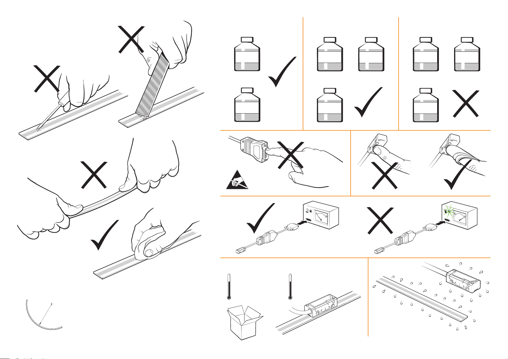
Storage and handling
Scale and readhead
N-heptane
Scale only
Acetone
Readhead only
Acetone
CH3(CH2)5CH
Propan-2-ol
CH3CHOHCH
3
3
CH3COCH
Methylated
Spirits
3
Chlorinated
Solvents
CH3COCH
Methylated
Spirits
3
Chlorinated
Solvents
Minimum bend radius
RSLM20 – 250 mm
RELM20 – DO NOT BEND
NOTE: Ensure self-adhesive tape
is on outside of bend.
Storage
+70°C
−20°C
Operating
+70°C
0°C
Humidity
95% relative humidity
(non-condensing)
to IEC60068-2-78
5TONiC RSLM20/RELM20 Functional Safety installation guide and safety manual Original instructions
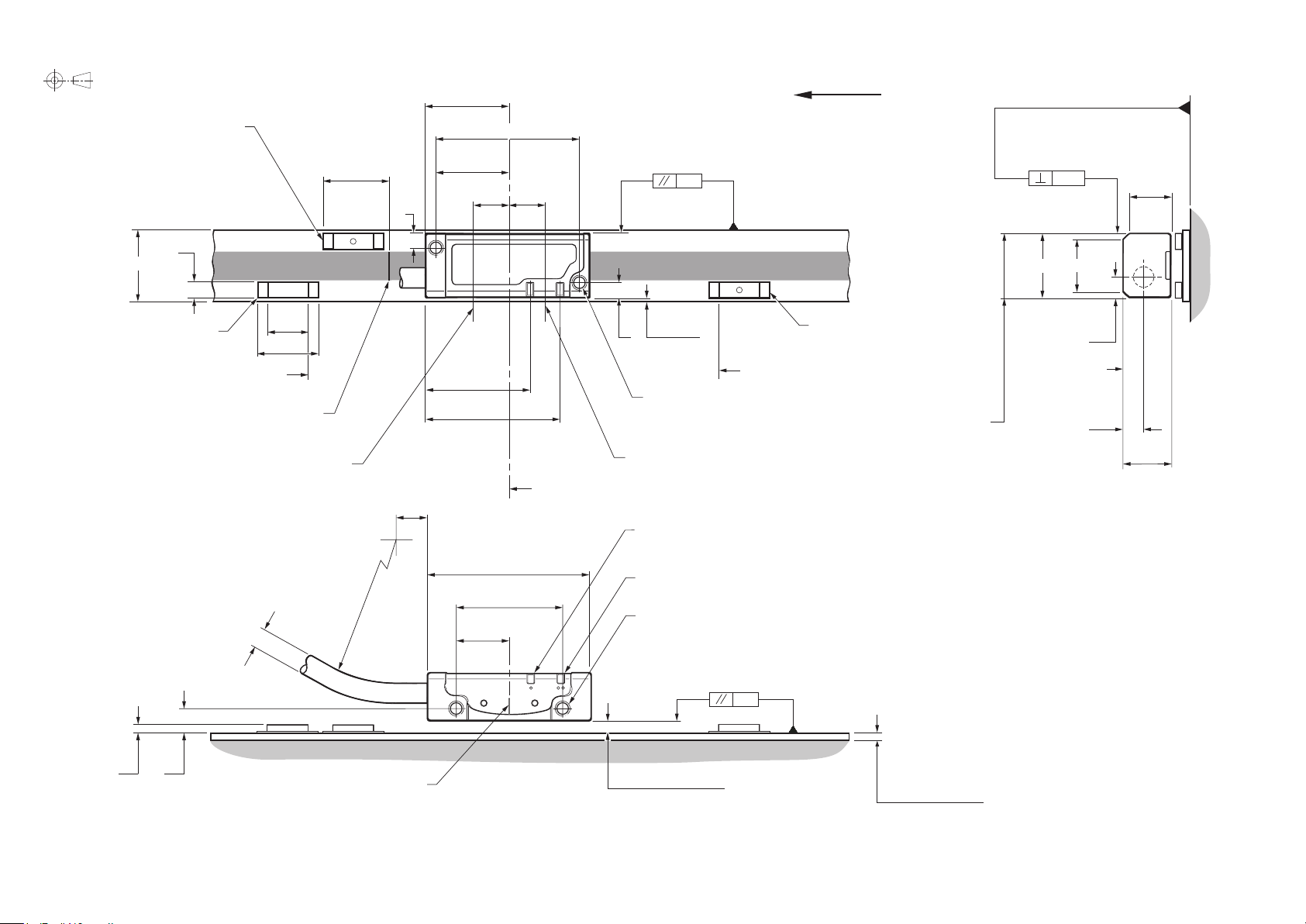
TONiC FS T301x readhead installation drawing
Dimensions and tolerances in mm
Reference mark selector magnet †
(A-9653-0143)
(Dimensions as P limit)
3.7
14.9 ±0.2
P limit magnet
(A-9653-0138)
Nominal P limit trigger point
Selected IN‑TRAC
Reference mark selector
R>20 Dynamic bend radius
R>10 Static bend radius
10
15
reference mark
sensor position
0.25
±
25
Ø4.
18
Forward direction of
31
15 ±1
16
7.8
3
7.8
(Yaw tol. ±0.4°)
0.25
Offset
3
0.7±0.5
22
2 mounting holes M2.5 through,
™
29
counterbored Ø3 × 2.75 deep
from alternative mounting face
P and Q limit switch sensor position
readhead relative to scale
Q limit magnet (A-9653-0139)
(Dimensions as P limit)
Nominal Q limit trigger point
Recommended
mounting faces
(Roll tol. ±0.5°)
0.08
11
*
13.5
Alternative
mounting
face
4.25
4.15
8.75
10
*
Optical centreline (incremental and reference mark)
6 min
Set-up LED
35
23
CAL/AGC LED
2 mounting holes M2.5 through, counterbored Ø3 × 2.3 deep both sides
‡
11.5
(Pitch tol. ±1°)
0.6
4.61.5
Optical centreline marker
*
Extent of mounting faces. † Reference mark selector magnet is only required with RSLC20 scale and T3010 readheads. ‡ Minimum thread engagement 5mm (7.5 including counterbore). Tightening torque 0.25 to 0.4 Nm.
NOTES: The reference mark selector and limit actuator locations are correct for the readhead orientation shown.
External magnetic elds greater than 6 mT, in the vicinity of the readhead, may cause false activation of the limit and reference sensors.
Rideheight 2.1 ±0.15
1.7 ±0.1 RSLM20
1.8 ±0.1 RELM20
6TONiC RSLM20/RELM20 Functional Safety installation guide and safety manual Original instructions
 Loading...