

Page 1

RSLM high accuracy linear encoder
Installation guide
M-9653-9225-05-C
TONiC™ T101x RSLM / RELM high accuracy linear encoder system
Page 2

Contents
Product compliance 1
Storage and handling 2
TONiC readhead installation drawing 3
Measuring lengths 4
Adhesive mounting installation drawing 5
Adhesive mounting installation 6
Clip/clamp mounting installation drawing 7
Clip/clamp mounting installation 8
TONiC interface drawing 9
TONiC quick-start guide 9
System connection 10
Readhead mounting and alignment 11
Reference mark selector and limit magnet installation 11
System calibration 12
Output signals 13
Speed 13
Electrical connections 14
Output specifications 15
General specifications 16
TONiC RSLM/RELM installation guide
Page 3
1TONiC RSLM/RELM installation guide
Disclaimer
RENISHAW HAS MADE CONSIDERABLE EFFORTS TO ENSURE THE CONTENT OF THIS DOCUMENT
IS CORRECT AT THE DATE OF PUBLICATION BUT MAKES NO WARRANTIES OR REPRESENTATIONS
REGARDING THE CONTENT. RENISHAW EXCLUDES LIABILITY, HOWSOEVER ARISING, FOR ANY
INACCURACIES IN THIS DOCUMENT.
Product compliance
C
Renishaw plc declares that TONiC complies with the applicable standards and regulations.
A copy of the EC Declaration of Conformity is available on request.
FCC compliance
This device complies with part 15 of the FCC Rules. Operation is subject to the following two conditions:
(1) This device may not cause harmful interference, and (2) this device must accept any interference
received, including interference that may cause undesired operation.
The user is cautioned that any changes or modifications not expressly approved by Renishaw plc or
authorised representative could void the user’s authority to operate the equipment.
This equipment has been tested and found to comply with the limits for a Class A digital device,
pursuant to part 15 of the FCC Rules. These limits are designed to provide reasonable protection
against harmful interference when the equipment is operated in a commercial environment.
This equipment generates, uses, and can radiate radio frequency energy and, if not installed
and used in accordance with the instruction manual, may cause harmful interference to radio
communications. Operation of this equipment in a residential area is likely to cause harmful
interference in which case the user will be required to correct the interference at his own expense.
NOTE: This unit was tested with shielded cables on the peripheral devices. Shielded cables must be
used with the unit to ensure compliance.
RoHS compliance
Compliant with EC directive 2011/65/EU (RoHS)
Patents
Features of Renishaw’s encoder systems and similar products are the subjects of the following
patents and patent applications:
EP1173731 US6775008B2 JP4750998 CNCN100543424C US7659992
EP1766334 JP4932706 CNCN100507454C US7550710 JP5386081
EP1766335 CNCN101300463B EP1946048 US7624513B2 JP5017275
CNCN101310165B US7839296 EP1957943 CN1314511 EP1469969
JP5002559 US8987633 US8466943
Further information
Further information relating to the TONiC encoder range can be found in the TONiC system Data sheet
(L-9517-9337). This can be downloaded from our website www.renishaw.com/encoder and is also available
from your local representative. This document may not be copied or reproduced in whole or in part,
or transferred to any other media or language, by any means without the written prior permission of Renishaw.
The publication of material within this document does not imply freedom from the patent rights of Renishaw plc.
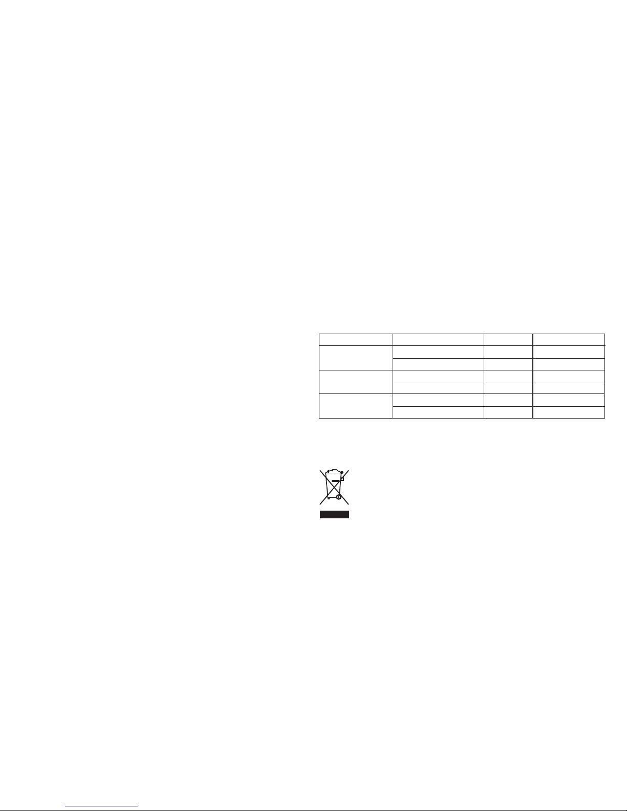
The use of this symbol on Renishaw products and/or accompanying documentation indicates that the product
should not be mixed with general household waste upon disposal. It is the responsibility of the end user to
dispose of this product at a designated collection point for waste electrical and electronic equipment (WEEE)
to enable reuse or recycling. Correct disposal of this product will help to save valuable resources and prevent
potential negative effects on the environment. For more information, please contact your local waste disposal
service or Renishaw distributor.
The packaging of our products contains the following materials and can be recycled.
Cardboard
Polypropylene
Low Density Polyethylene Foam
Cardboard
High Density Polyethylene Bag
Metalised Polyethylene
Not applicable
PP
LDPE
Not applicable
HDPE
PE
Outer box
Inserts
Bags
Recycling Guidance
ISO 11469
Material
Packaging Component
Recyclable
Recyclable
Recyclable
Recyclable
Recyclable
Recyclable
Page 4
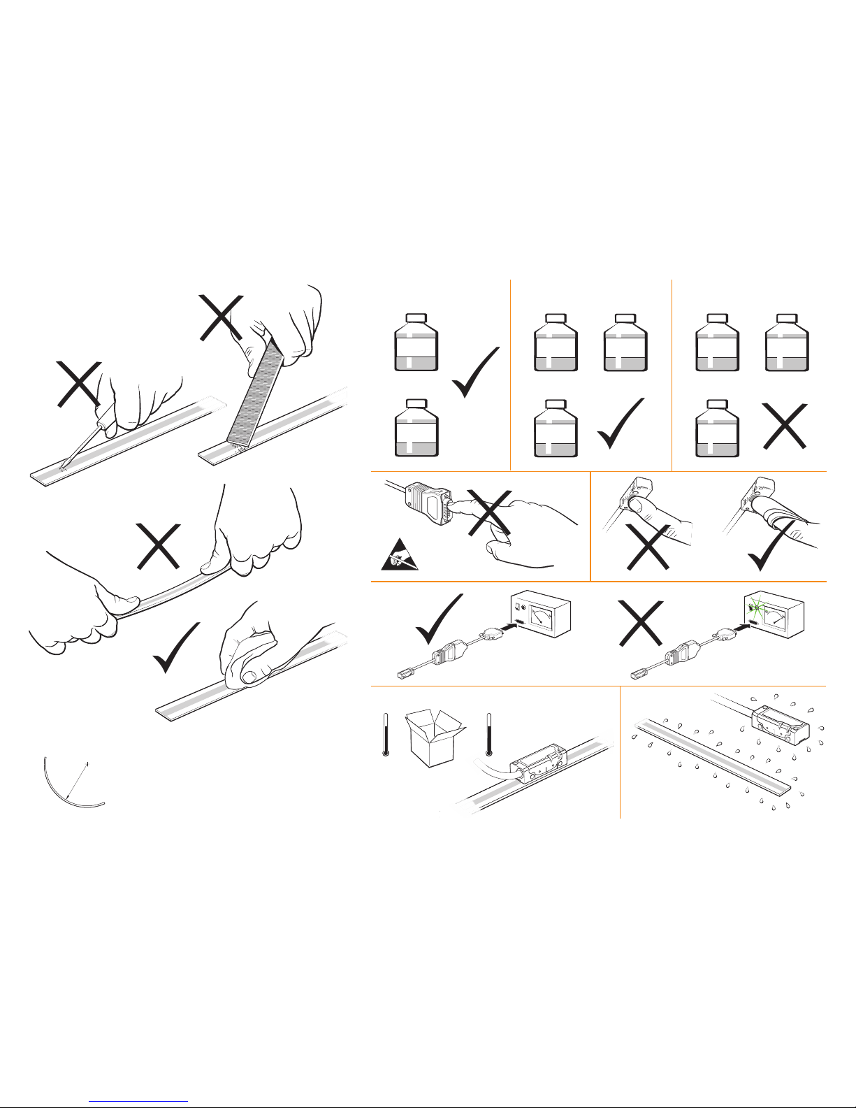
+70 °C
-20 °C
Storage
Operating
Storage and handling
+70 °C
0 °C
N-heptane
CH3(CH2)5CH
3
Propan-2-ol
CH3CHOHCH
3
Scale and readhead
Acetone
CH3COCH
3
Methylated
Spirits
Chlorinated
Solvents
Readhead only
Acetone
CH3COCH
3
Methylated
Spirits
Chlorinated
Solvents
Scale only
Minimum bend radius
RSLM – 250 mm
RELM – DO NOT BEND
NOTE: Ensure self-adhesive tape
is on outside of bend.
Humidity
95% relative humidity
(non-condensing)
to EN 60068-2-78
2
UHV readhead
Bakeout +120 °C
TONiC RSLM/RELM installation guide
Page 5
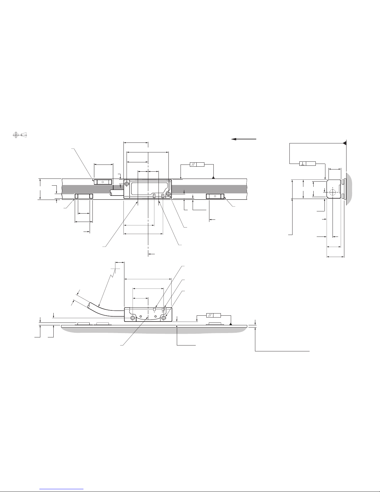
TONiC T101x readhead installation drawing
Dimensions and tolerances in mm
*
Extent of mounting faces. =UHV cable diameter 3.0 approx. ‡ Dynamic bend radius not applicable for UHV cables.
NOTE: External magnetic fields greater than 6 mT, in the vicinity of the readhead, may cause false activation of the limit sensor.
3
4.61.5
R>20 Dynamic bend radius
‡
R>10 Static bend radius
Ø4.25 ±0.25
=
35
23
11.5
6 min
2 mounting holes M2.5 through, counterbored Ø3 x 2.3 deep both sides
NOTE: The recommended thread engagement is 5 min (7.5 including counterbore)
and the recommended tightening torque is between 0.25 and 0.4 Nm.
Set-up LED
CAL/AGC LED
0.6
(Pitch tol. ±1°)
Rideheight
2.1 ±0.15
Alternative
mounting
face
2 mounting holes M2.5 through,
counterbored Ø3 x 2.75 deep
from alternative mounting face
Reference mark selector
sensor position
P and Q limit switch sensor position
P limit magnet
(A-9653-0138)
Recommended
mounting faces
(Roll tol. ±0.5°)
0.08
13.5
11*
8.75
*
4.15
4.25
10
12.1
0.25
(Yaw tol. ±0.4°)
16
15
10
7.8
7.8
Optical centreline (incremental and reference mark)
Optical centreline marker
18
14.9 ±0.2
Reference mark selector
(A-9653-0143)
Only required for
T1010 readheads
(Dimensions as P limit)
3.7
Q limit magnet (A-9653-0139)
(Dimensions as P limit)
3
0.7±0.5
3
31
Nominal P limit trigger point
Nominal Q limit trigger point
15 ±1
Forward direction of
readhead relative to scale
29
22
TONiC RSLM/RELM installation guide
1.5 (Clip/clamp mounting) RSLM
1.6 (Clip/clamp mounting) RELM
1.7 (Adhesive mounting) RSLM
1.8 (Adhesive mounting) RELM
Page 6
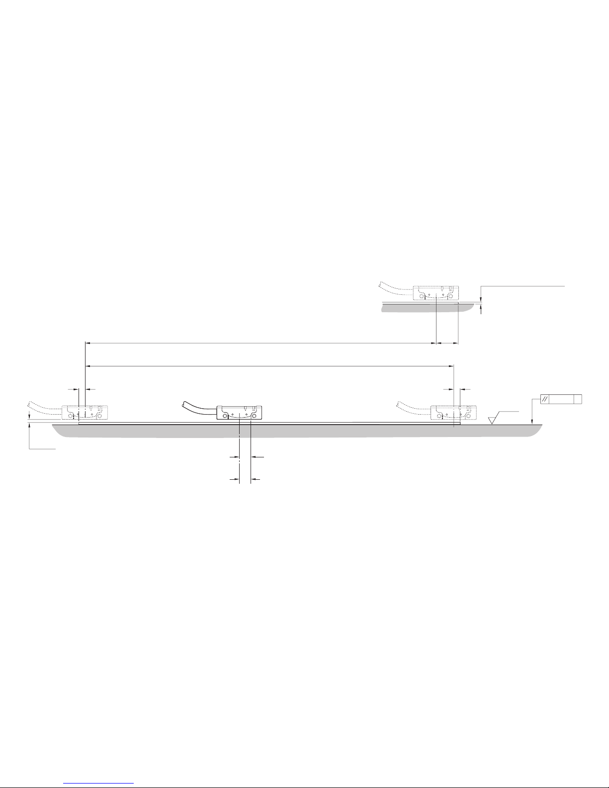
Measuring lengths
Dimensions and tolerances in mm
4
TONiC RSLM/RELM installation guide
17.5
ML = (L-10) without limits
Measuring length, ML = (L-25) with dual 10 mm limits
Optical centreline
(incremental and reference mark)
2.1 ±0.15
5
7.8
Ra 3.2
0.05
F
F = axis of motion
1.5 (Clip/clamp mounting) RSLM
1.6 (Clip/clamp mounting) RELM
1.7 (Adhesive mounting) RSLM
1.8 (Adhesive mounting) RELM
5
Limit sensor position
Page 7

L 4 m: L/2 ±0.5 L 4 m: L/2 ±2
14.9 ±0.2
6
0.05/50
0.5
F
Alignment dowels, maximum spacing 350
‡
F = axis of motion
NOTES:
Adhesive mounted scale should not be re-used after installation.
For readhead dimensions see ‘Readhead installation drawing’.
When installing in a groove allow a tolerance for scale width.
See ‘Measuring length’ for information on using limits.
Reference mark position
Reference mark position
L
Adhesive mounting installation drawing
Dimensions and tolerances in mm
L
L/2 ±0.25
20 ±0.25
12
10
RGG-2, 2-part epoxy (A-9531-0342), usually positioned
coincident with user selected scale datum
Double-sided
adhesive tape
*Reference marks positioned equi-distant from scale ends.
Double-sided adhesive tape is included with all scale lengths.
‡
When scale is to be mounted horizontally on a vertical surface, position the dowels so that the datum edge is supported.
Adhesive datum clamp
Clamping in this way ensures scale positional stability relative to substrate.
14.9 ±0.2
6
0.05/50
0.5
F
F = axis of motion
Alignment dowels, maximum spacing 350
‡
RSLM Use with T1011 readhead
(Centre reference mark)
Datum edge
Datum edge
20 ±0.25
Option A reference mark position
(for 10 mm limits)
Option B reference mark position
(for 20 mm and 50 mm limits)
70 ±0.25
RSLE Use with T1011 readhead
(End reference mark)
200
Select one or more reference marks
using reference mark selector magnet
(A-9653-0143)
20 x 120*
RSLC Use with T1010 readhead
(Customer selected reference mark)
RELM Use with T1011 readhead
(Centre reference mark)
RELE Use with T1011 readhead
(End reference mark)
5
TONiC RSLM/RELM installation guide
Page 8

6
3
Adhesive mounting installation
1
Clean underside of scale using approved solvents
(see ‘Storage and handling’).
4
Thoroughly mix and apply epoxy then
remove remaining backing liner.
Area for
RGG-2 epoxy
6
Support
dowels
7
Remove excess
epoxy
or
5
Locate scale against dowels or ledge
and rotate down onto substrate.
Press down with firm
finger pressure.
2
Mark area for epoxy on
adhesive tape.
8
Mounting ledge
Thoroughly clean and degrease
the substrate with a
lint-free cloth.
Remove backing liner from one side
and stick to underside of scale.
TONiC RSLM/RELM installation guide
Allow 24 hours for epoxy to cure fully, then
clean scale using Renishaw scale wipes
(A-9523-4040) or a clean, dry, lint-free cloth.
Page 9

L
24
Mounting clip
20
12
21
13
20 ±0.25
31
31
Datum clamp
(see note)
Mounting clip
(A-9584-2049)
L
4 m: L/2 ±0.5 L 4 m: L /2 ±2
13.5
1.8
(clip height)
13.6
14.9 ±0.2
6
23 ±0.25
Special M3 low-profile
screw with 1.5 mm
hex socket.
(A-9584-2047 pack of 25)
0.05/50
0.5
F
F = axis of motion
Clip/clamp mounting installation drawing
Dimensions and tolerances in mm
70 ±0.25
Option A
Reference mark position
(for 10 mm limits)
Option B
Reference mark position
(for 20 mm and 50 mm limits)
20
12
Reference mark
position
23 ±0.25
1.9
(clamp height)
Special M3 low-profile
screw with 1.5 mm
hex socket.
(A-9584-2047 pack of 25)
Scale centreline
Counterbore all mounting
holes 3.2 mm diameter
1 mm to 1.5 mm deep 6 mm
minimum depth full thread.
6.75
Datum clamp
(A-9584-2050)
150
75
150
75
150
75
150
75
20
12
20
12
20 ±0.25
31
NOTES:
Datum clamp usually coincident with selected
IN-TRAC reference mark. However the position is
user selectable depending upon application.
For lengths 80 L 190 ensure scale is clamped
or clipped in the middle as well as at both ends.
*Clips omitted for clarity. Reference marks
positioned equi-distant from scale ends.
For optimum performance the readhead should
be installed close to nominal geometry.
Care should be taken to ensure sufficient
clearance between the readhead/mounting
bracket and clips/datum clamp.
Only special low-profile screws should be used.
Screws are provided with all clips/datum clamps
and spares can be supplied if required.
Datum edge
RSLM
Use with T1011 readhead
(Centre reference mark)
L
24
Mounting clip
20
12
21
13
31
Datum clamp
(see note)
L/2 ±0.25
6
150
150
0.05/50
0.5
F
F = axis of motion
Datum edge
RELM
Use with T1011 readhead
(Centre reference mark)
RSLE
Use with T1011 readhead
(End reference mark)
200
20
x 120
Select one or more reference marks
using reference mark selector magnet
(A-9653-0143)
RSLC*
Use with T1010 readhead
(Customer selected
reference mark)
RELE
Use with T1011 readhead
(End reference mark)
14.9 ±0.2
7
TONiC RSLM/RELM installation guide
Page 10

8
3
Fit remaining clips using clip setting shim M-9584-0928
(provided with A-9584-2050 clamp set).
4
Place datum clamps against scale and secure using the
special M3 low-profile screws supplied.
Torque 0.5 Nm
5
Clean scale
Clip/clamp mounting installation
1
2
Fit clips on one side of scale and align to the specification given in the installation drawing.
Only the special low-profile screws supplied with the clips should be used.
Additional screws can be purchased from Renishaw (A-9584-2047 pack of 25).
NOTE: When mounting scale to vertical surfaces, temporary bridge clamps
(A-9584-2112) are available which support the scale prior to fitting clips.
Torque 0.5 Nm
Clean underside of scale using approved solvents
(see ‘Storage and handling’).
TONiC RSLM/RELM installation guide
Thoroughly clean and degrease
the substrate with a
lint-free cloth.
Page 11

9
15
1
8
9
TONiC interface drawing
Dimensions and tolerances in mm
16
4- 40 UNC x 2
40
6 min
62
67
CAL/AGC push button switch
access hole Ø2.4
33.3
>R20 Dynamic bend radius*
>R10 Static bend radius
8
Diagnostic LED
(
Ti0004 - Ti20KD
and
TD4000 - TD0040)
Cover plate
CAL button operation
Push and release (<3 seconds) - Calibration (CAL) routine enable/disable
Push and release (>3 seconds) - Automatic Gain Control (AGC) enable/disable
Push and hold during power ‘Off/On’ cycle - Restore factory defaults
Refer to readhead LED functionality chart for CAL LED indications
TONiC quick-start guide
This section is a quick-start guide to installing a TONiC system.
More detailed information on installing the system is contained in the
following sections of the Installation guide.
INSTALLATION
Ensure scale, readhead optical window and mounting faces are clean and free from obstructions.
If required, ensure reference mark selector magnet is correctly positioned.
Plug the readhead cable into the Ti/TD interface under the cover plate and reassemble interface.
Connect to receiving electronics and power-up.
Ensure AGC is switched off - the CAL LED on the readhead should be off (if not press and hold the
CAL button on the interface until the CAL LED on the readhead switches off).
Install and align the readhead to maximise signal strength over the full axis of travel as indicated by the
readhead and interface set-up LEDs (readhead - Green; interface - ideally Blue/Purple).
CALIBRATION
Press and release the CAL button on the interface.
The CAL LED on the readhead will be single flashing.
Move the readhead along the scale at slow speed (<100 mm/s),
without passing a reference mark, until the CAL LED starts double flashing.
The system is now calibrated and ready for use.
AGC can now be switched on if required by pressing and holding the CAL button
until the CAL LED on the readhead switches on.
CAL values and AGC status are stored in readhead non-volatile memory at power down.
NOTE: If calibration fails, restore factory defaults by pressing and holding the CAL button
whilst switching on. Then repeat the installation and calibration routine.
No reference mark
If a reference mark is not being used,
the calibration routine should now be exited
by pressing and releasing the CAL button.
The CAL LED will stop flashing.
(Incremental CAL values are automatically stored)
Reference mark
Move the readhead back and forth over the
selected reference mark until the CAL LED
stops flashing and remains ‘off’.
(Incremental and reference mark CAL values
are automatically stored)
*Dynamic bend radius not applicable for UHV cables.
TONiC RSLM/RELM installation guide
Page 12

10
System connection
Approved ESD precautions must be followed at
all times during readhead and interface electrical
connections. The readhead is connected to the
Ti/TD interface via a small, rugged connector to
allow for easy feed-through during installation.
Connecting the readhead
1
Remove the cover plate as shown
(2 x M2.5 hex head screws).
2
Taking care not to touch the pins, plug the
connector into the socket in the interface,
ensuring correct orientation as shown.
3
Refit the cover plate ensuring the cable ferrule is located in the recess on the inside and no wires are trapped under the cover plate.
TONiC RSLM/RELM installation guide
3
Place the connector in an anti-static bag.
4
Refit the cover plate.
Disconnecting the readhead
1
Remove the cover plate on the interface
(2 x M2.5 hex head screws).
2
Gently lever the connector PCB
(on the end of the cable) out of
the socket.
Do not pull the cable to remove
the connector.
Page 13

Correct position of
reference selector
for readhead
orientation shown
(Only required with
T1010 heads)
P limit magnet
Applicator tool
(A-9653-0201)
Remove
self-adhesive
backing paper
IN-TRAC reference mark
Q limit magnet
Readhead mounting and alignment
Mounting brackets
The bracket must have a flat mounting surface and should provide adjustment to enable
conformance to the installation tolerances, allow adjustment to the rideheight of the readhead,
and be sufficiently stiff to prevent deflection or vibration of the readhead during operation.
Readhead set-up
Ensure that the scale, readhead optical window and mounting face are clean and free from
obstructions. To set nominal rideheight, place the Green readhead spacer with the aper ture
under the optical centre of the readhead to allow normal LED function during set-up
procedure. Adjust the readhead to maximise the signal strength along the full axis of travel
to achieve a Green set-up LED on the readhead (>70% signal). If a digital Ti/TD interface is
used, aim for a Blue LED on the interface.
NOTE: The readhead should be installed and set-up with the AGC switched off
(CAL LED off). When re-installing, factory defaults should be restored.
Green Orange Red
Readhead set-up LED status
Ya w
0° ±0.4°
Pitch
0° ±1°
Roll
0° ±0.5°
Rideheight
2.1 ± 0.15 mm
Green spacer
Reference mark selector and limit magnet installation
For accuracy and ease of positioning of reference mark selector and limit magnets, the applicator tool (A-9653-0201)
should be used. The magnet should be attached to the applicator tool as shown below.
Limit magnets can be positioned at any user defined location along the scale, but the reference mark selector magnet
(T1010 readhead only) should be positioned adjacent to the chosen IN-TRAC reference mark as shown below.
As the TONiC readhead passes the reference mark selector magnet or limit switch magnet, a force of up to 0.2 N is
generated between the magnet and the concentrators on the readhead. The design of the bracket should be sufficiently
stiff so that it is able to tolerate such force without distorting. Following the clamping instructions on the scale installation
will prevent this magnetic force from disturbing the scale.
NOTE: Reference and limit magnets may creep when influenced by magnetic materials in close proximity.
In such cases, they should be held in place using an additional fillet of
epoxy glue or similar at each end of the magnet assembly.
Limit trigger point
The limit output is nominally asserted when the readhead
limit switch sensor passes the limit magnet leading edge,
but can trigger up to 3 mm before that edge.
11
TONiC RSLM/RELM installation guide
Page 14

System calibration
Calibration is an essential operation that completes readhead set-up, with the optimum incremental
and reference mark signal settings stored in the readhead’s non-volatile memory.
Before system calibration:
uClean the scale and readhead optical window (contamination around the reference mark
may result in reference mark dephasing).
uIf re-installing restore factory defaults.
uMaximise the signal strength along full axis of travel.
NOTE: CAL routine maximum speed <100 mm/s (all Ti/TD interface models).
TD interface can be calibrated in either resolution.
Step 1 – Incremental signal calibration
uEnsure Automatic Gain Control is switched off
(CAL LED on readhead is not illuminated) before beginning calibration.
uPress and release the CAL button on the end of the interface using
a 2 mm allen key or similar tool.
WARNING! Activating the CAL switch only requires 2.5 N force.
Applying excess force may permanently damage the switch.
u The CAL LED will now periodically single-flash to indicate that
it is in incremental signal calibration mode.
u Move the readhead along the axis, ensuring you do not pass
the selected reference mark, until the CAL LED starts
double-flashing, indicating the incremental signal is now
calibrated and the new settings are stored in the
readhead memory.
u The system is now ready for reference mark phasing.
u For systems without reference mark, go to ‘Calibration routine - manual exit’
u If the system does not automatically enter the reference mark phasing stage (no double-flashing of the
CAL LED) the calibration of the incremental signals has failed. After ensuring failure is not due to overspeed
(>100 mm/s), exit the calibration routine, restore factory defaults and check the readhead installation and
system cleanliness before repeating the calibration routine.
Step 2 – Reference mark phasing
u Move the readhead back and forth over the selected reference mark until the CAL LED stops flashing
and remains off. The reference mark is now phased.
u The system automatically exits the CAL routine and is ready for operation.
u If the CAL LED continues double-flashing after passing the chosen reference mark many times,
it is not detecting the reference mark. Ensure that the correct readhead configuration is being used.
Readheads can either output all reference marks or only output a reference mark where
a reference selector magnet is fitted.
Calibration routine – manual exit
u To exit the calibration routine at any stage press the CAL button. The CAL button will then stop flashing.
Restoring factory defaults
When re-installing the system, or in the case of continued calibration failure, factory defaults should be restored.
To restore factory defaults;
u
Switch system off.
u
Press and hold the CAL button whilst switching the system on. The CAL LED on the readhead will flash
several times, indicating that the factory defaults have been restored.
12
u
Release CAL button.
u
Check the ‘Readhead mounting/installation’ and re-calibrate the system.
NOTE: System must be re-calibrated after restoring factory defaults.
Switching Automatic Gain Control (AGC) on or off
AGC can be switched on or off via the interface.
u Press and hold the CAL button on the interface for >3 seconds to switch AGC on or off. The CAL LED on
the readhead will be illuminated when AGC is active.
NOTE: The system must be calibrated before switching AGC on.
Ti0004 to Ti20KD and TD4000 to TD0040 Interface LED diagnostics
Normal setup; signal level 110% to 135%
Optimum setup; signal level 90% to 110%
Normal set-up: signal level 70% to 90%
Acceptable set-up; signal level 50% to 70%
Poor set-up; signal may be too low for reliable operation;
signal level <50%
Poor set-up; signal level <20%; system in error
Over speed; system in error
Over signal; system in error
Reference mark detected (speed <100 mm/s only)
Status
Signal
Alarm output*
Indication
Incremental
Reference mark
Purple
Blue
Green
Orange
Red
Red / blank - flashing
Blue / blank - flashing
Purple / blank - flashing
Blank flash
No
No
No
No
No
Ye s
Ye s
Ye s
No
*
Alarm output will take the form of 3-state or line driven E- signal depending on interface configuration.
Also, some configurations do not output overspeed alarm. See product nomenclature for details.
-Momentar y status only, while fault condition remains.
-Alarm may result in axis position error, re-datum to continue.
T101x readhead LED diagnostics
Normal set-up: signal level >70%
Acceptable set-up; signal level 50% to 70%
Poor set-up; signal may be too low for reliable operation; signal level <50%
Normal phasing
Acceptable phasing
Poor phasing; clean scale and recalibrate if required
Automatic Gain Control – On
Automatic Gain Control – Off
Calibrating incremental signals
Calibrating reference mark
Restore factory defaults
Status
Set-up
CAL
LED
Indication
Incremental
Reference mark
Operating
Calibration
Reset
Green
Orange
Red
Green (flash)
*
Orange (flash)
Red (flash)
On
Off
Single flashing
Double flashing
Flashing at
power-up (<2s)
*
Flash will effectively be invisible when incremental signal level is >70% when passing reference mark.
CAL LED
Single flashing
Double flashing
Off (auto-complete)
Settings stored
None, restore factory defaults and re-calibrate
Incremental only
Incremental and reference mark
TONiC RSLM/RELM installation guide
Page 15

Speed
Clocked
output option
(MHz)
50
40
25
20
12
10
08
06
04
01
Maximum speed (m/s)
Ti0004
5 µm
10
10
10
10
10
10
10
10
10
4.2
Ti0020
1 µm
10
10
10
10
9
8.10
6.48
4.50
3.37
0.84
Ti0040
0.5 µm
10
10
8.10
6.75
4.50
4.05
3.24
2.25
1.68
0.42
Ti0100
0.2 µm
6.48
5.40
3.24
2.70
1.80
1.62
1.29
0.90
0.67
0.16
Ti0200
0.1 µm
3.24
2.70
1.62
1.35
0.900
0.810
0.648
0.450
0.338
0.084
Ti0400
50 nm
1.62
1.35
0.810
0.675
0.450
0.405
0.324
0.225
0.169
0.042
Ti1000
20 nm
0.648
0.540
0.324
0.270
0.180
0.162
0.130
0.090
0.068
0.017
Ti2000
10 nm
0.324
0.270
0.162
0.135
0.090
0.081
0.065
0.045
0.034
0.008
Ti4000
5 nm
0.162
0.135
0.081
0.068
0.045
0.041
0.032
0.023
0.017
0.004
Ti10KD
2 nm
0.0654
0.054
0.032
0.027
0.018
0.016
0.013
0.009
0.0068
0.0017
Ti20KD
1 nm
0.032
0.027
0.016
0.013
0.009
0.0081
0.0065
0.0045
0.0034
0.0008
Analogue output
10 (-3dB)
Output signals
Interface output (analogue) Ti0000 only
Signal
Output type
Pin
Function
Power
Incremental signals
Reference mark
Limits
Set-up
Calibrate
Shield
Cosine
Analogue
Sine
Analogue
Open collector
–
–
–
–
4
5
12
13
9
1
10
2
3
11
7
8
6
14
Not connected
Case
5 V Power
5 V Sense
0 V Power
0 V Sense
Vp
Vq
V
X
CAL
Inner shield
Outer shield
V1
V2
V
0
+
-
+
-
+
-
Interface
Ti0000
NOTE: TD maximum speeds are resolution dependent as defined above.
Output connector
for all interfaces;
15 way D-type plug
Interface output (digital) Ti0004 to Ti20KD
and TD4000 to TD0040
Output type
RS422A
digital
RS422A
digital
Open collector
RS422A digital
–
–
–
–
Becomes alarm (E+) for Ti options E, F, G, H
‡
The alarm signal can be output as a line driver signal or 3-state. Please select the preferred option at time of ordering.
>
On TD interfaces pin 10 should be connected to 0 V to switch to lower resolution.
Power
Incremental
Reference mark
Limits
Set-up
Alarm
‡
Resolution switching
>
Shield
Function
Signal
Pin
Pin
7, 8
2, 9
14
6
13
5
12
4
11
10
1
–
3
–
–
Case
7, 8
2, 9
14
6
13
5
12
4
–
–
1
11
3
10
–
Case
Interface
Ti0004 - Ti20KD
TD4000 - TD0040
5 V
0 V
–
Inner shield
Outer shield
A
B
Z
+
-
+
-
+
-
+
-
P
Q>
X
E
Readhead output
Signal
Output type
Function
Power
Incremental signals
Reference mark
Limits
Set-up
Calibrate
Shield
Cosine
Analogue
Sine
Analogue
Open collector
–
–
–
–
Colour
Brown
White
Red
Blue
Yellow
Green
Violet
Grey
Pink
Black
Clear
Orange
Green/Yellow
Outer screen
5 V
0 V
Vp
Vq
V
X
CAL
Inner shield*
Outer shield
V1
V2
V
0
+
-
+
-
+
-
13
*
No inner shield on UHV cables.
TONiC RSLM/RELM installation guide
Page 16

Analogue outputs
V0 V1 V2-
V
0
V1 V2+
120R
Vp Vq P Q
R*
5 to 24 V
*Select R so maximum current does not exceed 20 mA.
Alternatively use a suitable relay or opto-isolator.
Limit output (No limits on TD interfaces)
Remote CAL operation (Analogue versions only)
CAL
0 V
All Ti/TD interfaces include a push button switch to enable CAL/AGC
features. However, remote operation of the CAL/AGC is possible via
pin 14 of analogue Ti0000 interfaces. For applications where no
interface is used, remote operation of CAL/AGC is essential.
TD interface resolution switching
Pin 10
0 V
Connect pin 10 to 0 V to switch to lower resolution.
Recommended signal termination
Digital outputs
Electrical connections
TONiC grounding and shielding
Single ended alarm signal termination (Ti options A, B, C, D)
Customer
electronics
Interface
5 V
4k7
4k7
1k8
100R
100nF
E-
14
TONiC RSLM/RELM installation guide
Standard RS422A line receiver circuitry.
Capacitors recommended for improved noise immunity.
Customer
electronics
120R
A B Z-
Cable Z0 = 120R
Readhead
A B Z+
0 V
0 V
220 pF
220 pF
Ti/TD interface
Customer
electronics
Extension cable max.
50 m dependent upon
output frequency
Inner shield
Outer shield
Output
signals
0 V
5 V
Readhead
IMPORTANT: The outer shield should be connected to the machine earth (Field Ground). The inner shield
should be connected to 0 V at receiving electronics only. Care should be taken to ensure that the inner and
outer shields are insulated from each other. If the inner and outer shields are connected together, this will
cause a short between 0 V and earth, which could cause electrical noise issues.
NOTE: Maximum cable length between readhead and Ti/TD interface is 10 m
Page 17

20 µm
45°
Alarm asserted when signal level is less than 20% or
greater than 135%. Alarm is also asserted if readhead
speed is too high for reliable operation.
E- output only for Ti options A, B, C, D
or 3-state alarm
Differentially transmitted signals forced open circuit for
>15 ms when alarm conditions valid.
Output specifications
Digital output signals
Form – Square wave differential line driver to EIA RS422A (except limits P and Q)
Analogue output signals
Incremental 2 channels V1 and V2 differential sinusoids in quadrature (90° phase shifted)
(V1 +)- (V1 -)
(V2 +)- (V2 -)
Bi-directionally repeatable
Differential pulse V0,
centred on 45°
(V0 +)- (V0-)
Reference
0.8 to 1 Vpp
360° (nominal)
0°
Alarm Asynchronous pulse
Line driven
Limits Open collector output, asynchronous pulse
Digital Ti interfaces only
Limits Open collector output, asynchronous pulse
Ti0000 interface only
Repeatability
<0.1 mm
Length of limit actuator
Vp V
q
T101x readhead only
Active low
Vp V
q
Repeatability
<0.1 mm
Length of limit actuator
Active high
Repeatability
<0.1 mm
Length of limit actuator
P Q
Active high or Active low
P Q
Repeatability
<0.1 mm
Length of limit actuator
Incremental 2 channels A and B in quadrature (90° phase shifted)
Reference
Signal period
Resolution
A
B
Z
Z
Bi-directionally repeatable pulse Z, duration equal to the resolution
Bi-directionally repeatable pulse Z, duration equal to the signal period
Wide reference
Set-up
*
Voltage
at V
X
3.3 (nom)
50%
70%
100%
0
0
Signal level
Between 50% and 70% signal level, VX is a duty cycle, 20 µm duration.
Time spent at 3.3 V increases with incremental signal level.
At >70% signal level VX is nominal 3.3 V.
E
>15 ms
Set-up
*
0
Voltage
at X
1
100%
0
Signal level
Set-up signal voltage proportional to incremental signal amplitude
NOTE: Ti0000 interface contains a transistor to invert the readhead’s ‘active low’ signal to give an ‘active high’ output.
*
Set-up signals as shown are not present
during calibration routine.
Inverse signals not shown for clarity
NOTE: No limits on TD interfaces. P limit becomes E+ for options E, F, G, H.
0.7 to 1.35 Vpp with Green LED indication,
(readhead) and 120R termination.
Centred on 1.65 V
NOTE: Ti0000A00V centred on 2.5 V
15
NOTE: Select ‘standard’ or ‘wide’ reference at time of ordering, to match the requirements of the controller being used.
Wide reference mark not available on Ti0004 interfaces.
TONiC RSLM/RELM installation guide
Page 18

Scale technical specifications
Mounting
Epoxy datum point and adhesive tape (nominal thickness 0.2 mm)
or datum clamp and mounting clips.
Reference mark IN-TRAC auto phase optical reference mark repeatable to unit
of resolution throughout specified temperature speed and range.
See installation drawings for information on reference mark position.
RSLM
Material Hardened martensitic stainless steel.
Form
1.5 mm x 14.9 mm (H x W)
Accuracy ±1.5 µm up to 1 m
±2.25 from 1 m to 2 m
±3 µm from 2 m to 3 m
±4 µm from 3 m to 5 m
(includes slope and linearity @20 °C).
Calibration traceable to International Standards.
Thermal expansion 10.1 ±0.2 µm/m/°C @20 °C
Maximum length 5 m
RELM
Material ZeroMet™. High stability, low-expansion nickel-iron alloy.
Form
1.6 mm x 14.9 mm (H x W)
Accuracy Certified to ±1µm (includes slope and linearity)@20 °C.
Calibration traceable to International Standards.
Thermal expansion 0.75 ±0.35 µm/m/°C @20 °C
Maximum length 1.5 m
Clocked output option
(MHz)
40 to 50
<40
analogue
Maximum
cable length (m)
25
50
50
General specifications
Power supply 5 V ±10% Readhead only <100 mA
T101x with Ti0000 <100 mA
T101x with Ti0004 – Ti20KD or TD4000 – TD0040 <200 mA
NOTE: Current consumption figures refer to
unterminated systems.
For digital outputs a further 25 mA per channel pair
(eg A+, A-) will be drawn when terminated with 120R.
For analogue outputs, a further 20 mA in total will be
drawn when terminated with 120R.
Powe r from a 5 V dc supply complying with the
requirements for SELV of standard IEC BS EN 60950-1.
Ripple 200 mVpp maximum @ frequency up to 500 kHz
Temperature (system) Storage -20 °C to +70 °C
Operating 0 °C to +70 °C
(UHV readhead) Bakeout +120 °C
Sealing (readhead) IP40
(interface) IP20
Acceleration (readhead) Operating 500 m/s2, 3 axes
Shock (system) Operating 500 m/s2, 11 ms, ½ sine, 3 axes
Vibration (system) Operating 100 m/s2, 55 Hz to 2000 Hz, 3 axes
Mass Readhead 10 g
Interface 100 g
Cable 26 g /m
UHV cable 14 g/m
Environmental Compliant with EU Directive 2011/65/EU (RoHS)
Readhead cable (standard) Double shielded, outside diameter 4.25 ±0.25 mm.
Flex life >20x106 cycles at 20 mm bend radius.
UL recognised component .
(UHV) Tin coated braided single screen FEP core insulation.
Maximum cable length
Readhead to interface 10 m
Interface to controller
Renishaw encoder systems have been designed to the relevant EMC standards,
but must be correctly integrated to achieve EMC compliance. In particular,
attention to shielding arrangements is essential.
16
TONiC RSLM/RELM installation guide
Page 19

RSLM high accuracy linear encoder
Renishaw plc
New Mills, Wotton-under-Edge,
Gloucestershire GL12 8JR
United Kingdom
T +44 (0)1453 524524
F +44 (0)1453 524901
E uk@renishaw.com
www.renishaw.com
For worldwide contact details,
please visit our main website at
www.renishaw.com/contact
*M-9653-9225-05*
RENISHAW® and the probe symbol used in the RENISHAW logo are registered trade marks
of Renishaw plc in the United Kingdom and other countries.
apply innovation and names and designations of other Renishaw products and technologies
are trade marks of Renishaw plc or its subsidiaries.
2008-2017 Renishaw plc All rights reser ved Issued 0217
 Loading...