

Page 1
1
Contents
Installation and operation manual
H-9942-9001-01-A
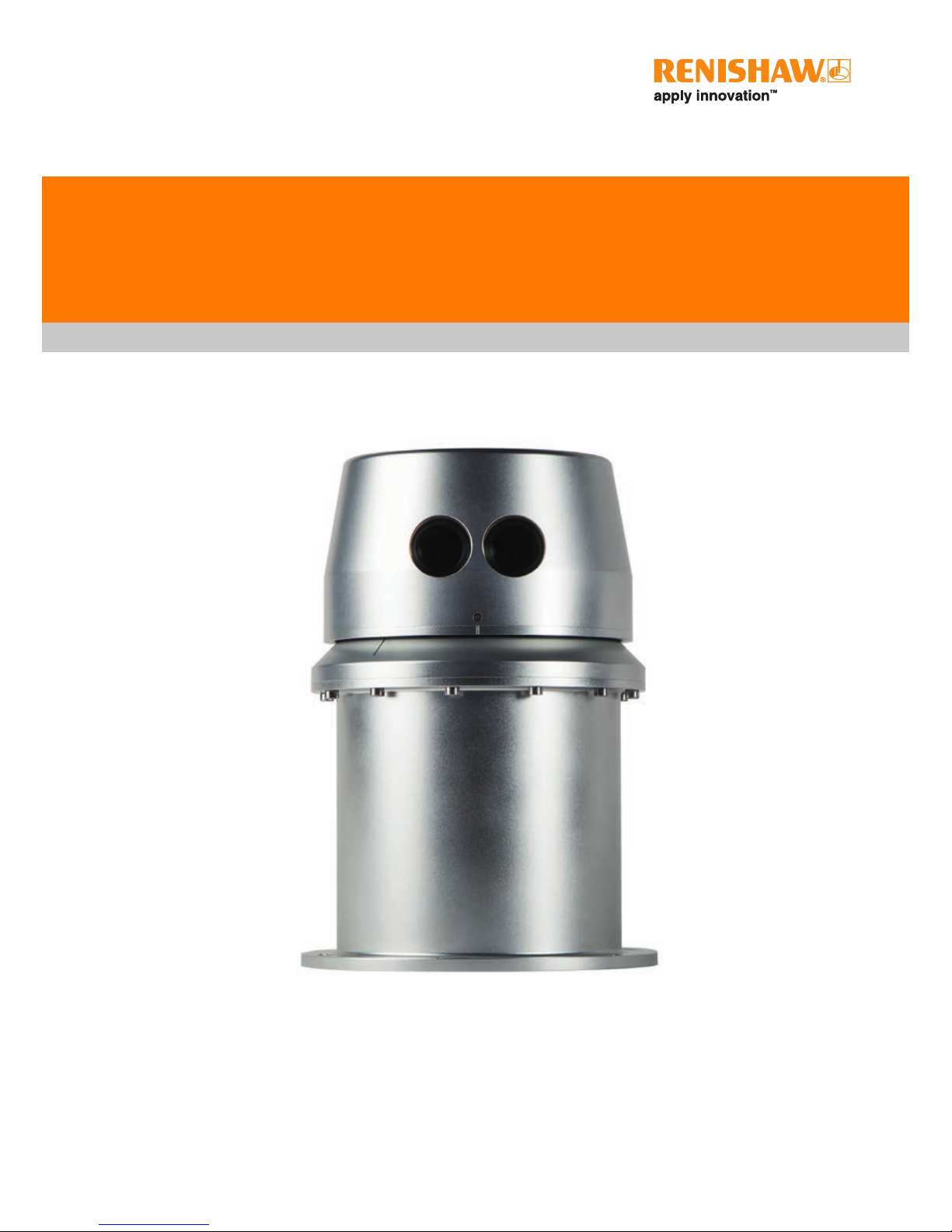
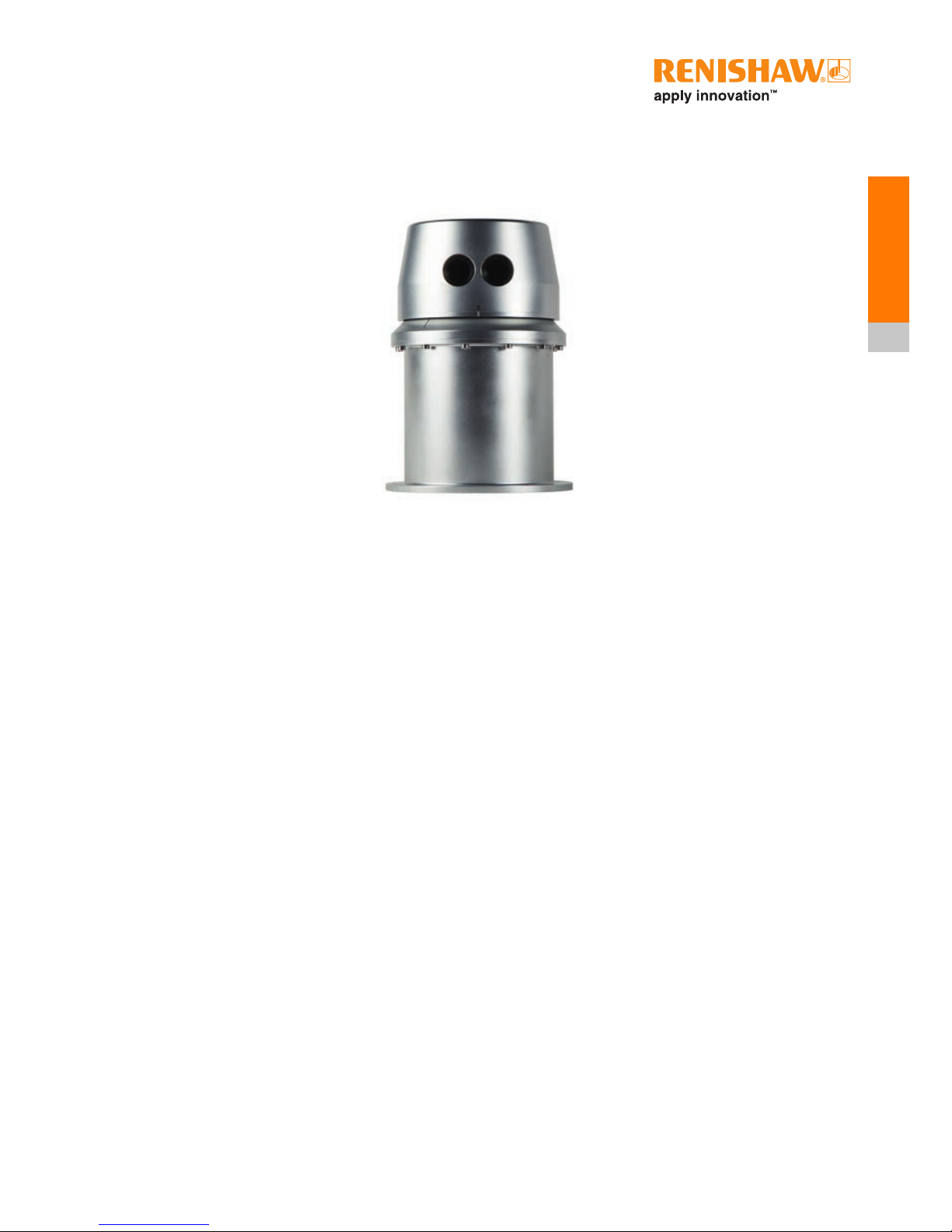
SLM 250 scanning laser module
For end users, installers,
integrators and engineers
Page 2

© 2016 Renishaw plc. All rights reserved.
This document may not be copied or reproduced
in whole or in part, or transferred to any other
media or language, by any means, without the
prior written permission of Renishaw plc.
The publication of material within this document
does not imply freedom from the patent rights of
Renishaw plc.
Renishaw part no: H-9942-9001-01-A
Issued:
10.2016
Trade marks
RENISHAW and the probe symbol used in the
RENISHAW logo are registered trade marks of
Renishaw plc in the United Kingdom and other
countries. apply innovation and names and
designations of other Renishaw products and
technologies are trade marks of Renishaw plc or
its subsidiaries.
All other brand names and product names used
in this document are trade names, trade marks,
or registered trade marks of their respective
owners.
Care of equipment
Renishaw’s SLM 250 and associated accessory
products are precision products and must
therefore be treated with care.
Changes to Renishaw products
Renishaw plc reserves the right to
improve, change or modify its products and
documentation without incurring any obligation
to make changes to equipment previously sold
or distributed.
Disclaimer
RENISHAW HAS MADE CONSIDERABLE
EFFORTS TO ENSURE THE CONTENT OF
THIS DOCUMENT IS CORRECT AT THE
DATE OF PUBLICATION BUT MAKES NO
WARRANTIES OR REPRESENTATIONS
REGARDING THE CONTENT. RENISHAW
EXCLUDES LIABILITY, HOWSOEVER
ARISING, FOR ANY INACCURACIES IN THIS
DOCUMENT.
Safety
The SLM 250 is a high-performance distance
meter. It is essential that the unit and all
accessories are operated in accordance with the
instructions in this operation manual and it is the
responsibility of the user to ensure that, in the
event of a failure on any part of the Renishaw
system, the laser system remains safe.
In the case of laser systems with powers or
speeds capable of causing injury, it is essential
that appropriate safety protection measures
are included in the machine usage. Further
guidance can be found in the European
BS EN ISO 12100 : 2010 Safety of machinery –
General principles for design – Risk assessment
and risk reduction.
Information to the equipment
supplier/installer
It is the equipment supplier’s responsibility
to ensure that the user is made aware of any
hazards involved in any operations involving
the SLM 250, including those mentioned in
Renishaw product literature.
Page 3
Warranty
Renishaw plc warrants its equipment provided
that it is operated exactly as defined in
associated Renishaw documentation.
Laser safety
DO NOT STARE DIRECTLY
INTO THE BEAM
In accordance with BS EN 60825-1: 2007 and
US standards 21CFR 1040.10 and 1040.11,
except for deviations pursuant to Laser Notice
no. 50, dated June 24, 2007, the SLM 250 is
classified as a Class 1 invisible laser product.
Safety eyewear is not required for the SLM 250.
Do not stare into the beam or shine it into
the eyes of others. It is safe to view a diffusereflected beam. Do not dismantle the unit in any
way; doing so may expose laser radiation in
excess of Class 1 limits.
CAUTION – LASER LIGHT IS BRIGHT AND
BLINDING – DO NOT SHINE AT AIRCRAFT
OR VEHICLES AT ANY DISTANCE
Safety information
The following symbol is used in this manual
wherever important safety information is
present.
Before proceeding with any
electrical connection or
operation of the laser system,
refer to the general safety
information listed throughout
this manual.
DECLARATION OF CONFORMITY
The SLM 250 meets or exceeds the
requirements of the following British and
European Standards:
BS EN ISO 12100 : 2010 –
Safety of machinery – General principles for
design
BS EN 61326-1 : 2013 –
Electrical equipment for measurement, control
and laboratory use – EMC requirements
Part 1 – General requirements
The tests were carried out in compliance with:
Immunity to Table 2 – Industrial locations
Emissions to Class A – Industrial locations
BS EN 60825-1 : 2007 –
Safety of laser products – Part 1: Equipment
classification and requirements
The SLM 250 therefore complies with the
following European Directives:
2006/42/EC – Machinery
2004/108/EC – Electromagnetic compatibility
(EMC) of electrical equipment
2006/95/EC – Low voltage directive (LVD)
relating to electrical equipment designed for use
within certain voltage limits (codified version)
It is declared that the equipment named has
been designed to comply with the relevant
sections of the referenced specifications and
is in accordance with the requirements of the
Directives.
Page 4
FCC (USA only)
Information to the user (47CFR section
15.19)
This device complies with Part 15 of the FCC
Rules. Operation is subject to the following two
conditions:
1. This device may not cause harmful
interference, and
2. This device must accept any interference
received, including interference that may
cause undesired operation.
Information to user (47CFR section 15.21)
The user is cautioned that any changes or
modifications not expressly approved by
Renishaw plc or authorised representative
could void the user’s authority to operate the
equipment.
Information to the user (47CFR section
15.105)
This equipment has been tested and found
to comply with the limits of a Class A digital
device, pursuant to Part 15 of the FCC Rules.
These limits are designed to provide reasonable
protection against harmful interference when
the equipment is operated in a commercial
environment. The equipment generates, uses
and can radiate radio frequency energy and,
if not installed and used in accordance with
the SLM 250 manual, may cause harmful
interference to radio communications.
c
EC declaration of conformity
Renishaw plc declares that the SLM 250
complies with the applicable standards and
regulations.
Renishaw plc hereby declares that the SLM 250
is in compliance with the essential requirements
and other relevant provisions of Directive
1999/5/EC.
Contact Renishaw plc or visit
www.renishaw.com for the full EC declaration of
conformity.
WEEE directive
The use of this symbol on Renishaw products
and/or accompanying documentation indicates
that the product should not be mixed with
general household waste upon disposal. It is
the responsibility of the end user to dispose
of this product at a designated collection point
for waste electrical and electronic equipment
(WEEE) to enable reuse or recycling. Correct
disposal of this product will help to save
valuable resources and prevent potential
negative effects on the environment. For more
information, please contact your local waste
disposal service or Renishaw distributor.
Page 5

i
Contents
Contents
1 General safety ..........................................................1-1
1.1 Operation and maintenance .........................................1-1
1.2 Warnings........................................................1-1
2 Customer information ....................................................2-1
2.1 Dear Customer ...................................................2-1
2.2 Manual .........................................................2-1
2.3 Product warranty..................................................2-2
3 Introduction ............................................................3-1
3.1 Applications......................................................3-2
4 Equipment description....................................................4-1
4.1 Precautions .....................................................4-2
4.2 Cables .........................................................4-2
4.2.1 Umbilical cable.............................................4-2
4.2.2 Low-voltage power connectors ................................4-3
4.2.3 Ethernet ..................................................4-3
4.3 Electrical .......................................................4-3
5 Laser safety............................................................5-1
5.1 SLM 250 ........................................................5-1
6 Operational guidelines....................................................6-1
6.1 System limitations ................................................6-1
Page 6

ii
Contents
SLM 250 installation and operation manual
7 Maintenance and care of the SLM 250 .......................................7-1
7.1 General ........................................................7-1
7.2 Preventative maintenance ..........................................7-1
7.2.1 In use ....................................................7-1
7.2.2 In storage ................................................7-2
7.2.3 In transportation ...........................................7-2
7.2.4 General ..................................................7-2
8 Network set-up..........................................................8-1
9 SLM 250 software .......................................................9-1
9.1 Installing the SLM 250 software ......................................9-1
10 Command list..........................................................10-1
11 Rotation speed and resolution.............................................11-1
12 Output formats.........................................................12-1
12.1 ASCII data format ................................................12-1
12.2 Binary data format................................................12-3
13 Beam and tilt angles ....................................................13-1
14 Specifications..........................................................14-1
15 Appendix A – Mechanical drawings.........................................15-1
16 Appendix B – Electrical connections ........................................16-1
Page 7

1-1
General safety
1 General safety
CAUTION: Before unpacking and installing the SLM 250, read the safety instructions below
carefully and ensure that they are followed at all times by all operators. Failure to do so could
adversely affect the performance of the SLM 250 and/or lead to personal injury. Operators must
be trained in the use and application of the SLM 250 and accompanying accessories before being
allowed to operate the equipment.
1.1 Operation and maintenance
Following the simple maintenance procedures below will prolong the operational life and continued
high performance of the system. The user should determine the frequency of inspection and
maintenance actions according to the conditions of use.
• The product should only be connected to using the approved connector type and wiring as
prescribed in section 4.2, “Cables”.
• Changing the SLM 250 port and IP addresses must be carried out using only the SLM 250
software application by appropriately trained personnel.
• Disconnect power before performing any maintenance operations.
• Maintenance is restricted to procedures described in section 7, “Maintenance and care of the
SLM 250”.
1.2 Warnings
• Beware of unexpected movement. The user(s) must remain outside the full working envelope of
the SLM 250 whilst in operation.
• It is the machine supplier’s responsibility to ensure that the user is made aware of any hazards
involved in operation, including those mentioned in Renishaw product documentation.
• The SLM 250 must be transported in Renishaw supplied packaging.
• This equipment is not suitable for use in a potentially explosive atmosphere.
Page 8

SLM 250 installation and operation manual
1-2
General safety
This page is intentionally left blank.
Page 9

2-1
Customer
information
2 Customer information
2.1 Dear Customer
We congratulate you on the purchase of an SLM 250. You are now the owner of a high quality laser
measurement device. However, we would ask you to take the time to work carefully through these
operating instructions before using the instrument and to keep the manual with the instrument at all
times.
If your system requires servicing or calibration, or if there are questions arising beyond the scope of
this manual, contact Renishaw’s Service and Support Centre. Contact details are on the back page
of this manual.
Alternatively, for information on your local Renishaw approved service centre, visit our website at
www.renishaw.com
For best service, please make a note of the serial number, which can be found on the instrument.
2.2 Manual
It is important that you read this manual carefully before using the instrument.
This manual gives a full description of the hardware components of the SLM
250.
Further information can be found in the Quick-start Guide which is part of the SLM 250 software
application (see section 9.1, “Installing the SLM 250 software”).
This manual has been compiled with care. However, should you discover any errors we would
be grateful if you could contact Renishaw directly. Reproduction in whole or in part, including
utilisation in machines capable of reproduction or retrieval, without the express written permission
of Renishaw plc, is prohibited. Reverse engineering is also prohibited. The information in this
document is subject to change without notice.
Page 10

SLM 250 installation and operation manual
2-2
Customer
information
2.3 Product warranty
Unless otherwise specified, Renishaw plc warrants the equipment for a period of twelve months
from the date of delivery. This warranty is given subject to the following conditions:
• Renishaw plc shall be under no liability in respect of any defects in the equipment arising from
any drawing, design or specification supplied or modification requested by the customer.
• Renishaw plc shall be under no liability in respect of defects arising from, wilful damage,
negligence, abnormal working conditions, failure to follow Renishaw’s instructions (whether oral
or in writing), misuse or alteration or repair of the equipment without Renishaw’s approval.
• Software is not covered by this warranty.
• Claims in respect of defective equipment must be intimated by notice in writing to Renishaw
plc and the equipment must be retained by the customer pending written instructions from
Renishaw.
• Following authorised return of the equipment, which must be made by the customer on freight
prepaid basis, Renishaw will examine the equipment and, if the claim is justified in Renishaw’s
opinion, will repair the defective equipment or will make replacement without charge. Renishaw
will have no further liability to the customer.
Page 11
3-1
Introduction
3 Introduction
The SLM 250 is a ruggedised field instrument designed to produce fast, efficient 2D laser scans of
the surrounding vicinity.
It is designed to be used as a multi-purpose scanning distance meter that is integrated into other
equipment for a variety of applications.
The module employs the “time of flight” measurement technique to calculate the distance to the
target. Up to 36,000 such measurements can be made every second up to a range of 250 metres
(standard Renishaw test conditions).
The SLM 250 is just one of many laser systems that have been designed by Renishaw. Other
products – such as the Quarryman, Boretrak, C-ALS (Cavity Auto-scanning Laser System), Void
Scanner and Dynascan – have all been proved over many years of demanding use around the
world. These products complement the SLM portfolio and provide a wide range of advanced
measurement solutions to industries including mapping, mining and quarrying, traffic, offshore and
manufacturing.
Figure 1: SLM 250
Page 12

SLM 250 installation and operation manual
3-2
Introduction
3.1 Applications
This unique instrument is suitable for a large number of surveying and measuring functions, such
as:
• security
• quarrying and mining
• coastal mapping
• topographical surveys
• highway infrastructure surveys
• vehicle/vessel positioning.
Page 13
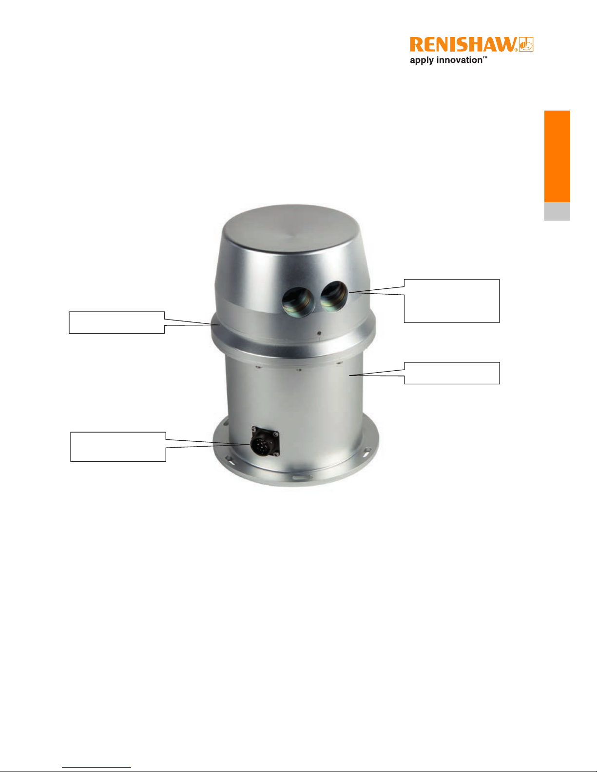
Figure 2: SLM 250 component parts
Laser module with
transmitting and
receiving optics
Aluminium housing
Rotation point
Power and data
interface
4-1
Equipment
description
4 Equipment description
The SLM 250 incorporates an embedded infrared laser module, a motor to spin the laser, encoders
to measure the rotation angle, the connector to provide power and data communications with the
unit, and the electronic circuitry that allows measurements to be taken at ranges up to 250 metres
from the instrument.
The two windows on the laser module protect the transmitting and receiving optics. It is through
these windows that the infrared measuring laser is fired and then received back into the instrument.
It can fire at up to 36,000 times per second.
The laser can range up to 250 metres. The actual range in any given project will depend on a
number of factors, such as atmospheric and environmental conditions, and the reflectivity of the
surface being targeted.
The laser is housed in an aluminium casing. This ensures that the SLM 250 is highly ruggedised
and may be used in demanding environments.
The flange at the bottom of the SLM 250 allows it to be mounted onto a stable surface (see section
15, “Appendix A – Mechanical drawings”). Its construction means it can be mounted vertically or
horizontally, with no loss of performance.
Page 14
SLM 250 installation and operation manual
4-2
Equipment
description
4.1 Precautions
• Avoid directing the laser apertures towards the sun or other high-powered, infrared light
sources.
• Avoid mechanical shock.
The laser is driven by a motor. When the unit is stationary the laser can be rotated by hand without
causing damage to the motor. If the laser is prevented from rotating by an obstruction, the motor
power will initially be increased to try to maintain the rotation speed but will then detect a stall
condition and the drive will be removed, preventing damage to the motor.
Caution: If the obstruction is removed before a stall is detected the rotation speed may
momentarily be in excess of what it should be.
It is advised to minimise any manual movement of the laser and to keep the instrument away from
potential obstructions so the motor may turn freely.
WARNING: Users should not manually or otherwise obstruct the operation of the
motor or allow clothing to come into contact with the device, to avoid entrapment
in the unit.
4.2 Cables
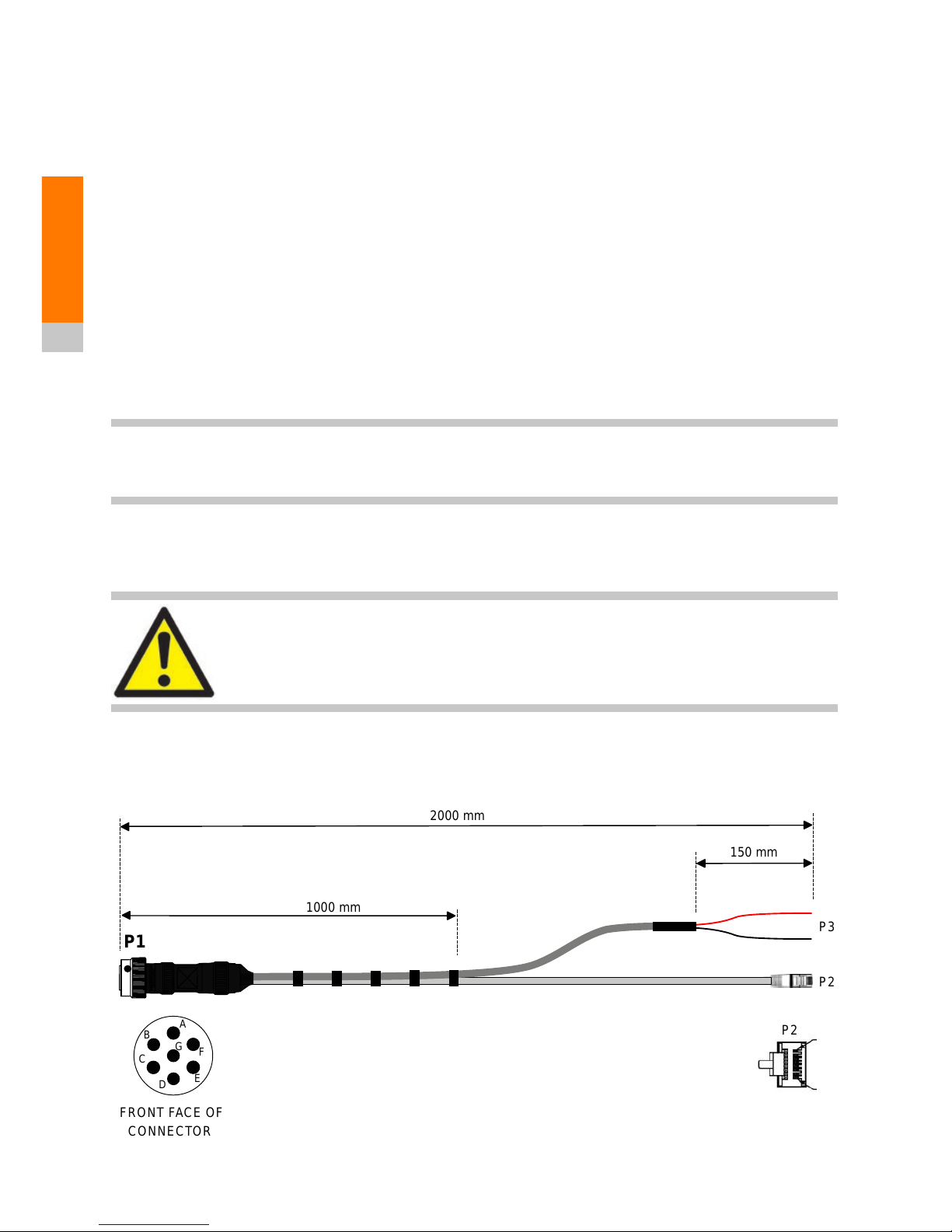
4.2.1 Umbilical cable
Figure 3: Umbilical cable
2000 mm
8
P2
P1
P2
P3
1000 mm
150 mm
8
8
1
2000 mm
P2
P1
P2
P3
1000 mm
150 mm
Wire Schedule
A
BCD
EFG
FRONT FACE OF
CONNECTOR
8
P2
8
8
1
Page 15

4-3
Equipment
description
The umbilical cable is 2 m in length and provides connection for power and Ethernet. Connection
to the SLM is by means of a Mil-Spec MIL-DTL-26482 Series 1 Plug (Renishaw recommends the
use of Weald LMH06T10.07SN.101). For further details of this cable see section 16, “Appendix B –
Electrical connections”.
4.2.2 Low-voltage power connectors
The 4 mm connector plugs are for connection to a low-voltage dc power supply of voltage range
11 Vdc to 16 Vdc.
For cable pin-outs, see section 16, “Appendix B – Electrical connections”.
4.2.3 Ethernet
The Ethernet connector (standard RJ45) allows for connection to a PC/laptop so that
communication to the SLM 250 can be established.
4.3 Electrical
WARNINGS:
• The SLM 250 has no user-serviceable parts. In the event of a problem, please
contact Renishaw’s Service and Support Centre.
• Do not attempt to open the instrument.
• Always isolate the low-voltage dc source before the instrument is removed
(uninstalled) and/or replaced (installed).
• Appropriate visual inspection and electrical safety testing is to be performed
after instrument installation or replacement.
It is recommended that the SLM 250 is powered from an external 14 Vdc source with a minimum
power capability of 100 W.
Note: The SLM motor start-up peak current will be higher than its steady running current,
especially when at the low end of its operating temperature range.
Page 16

SLM 250 installation and operation manual
4-4
Equipment
description
This page is intentionally left blank.
Page 17

5-1
Laser safety
5 Laser safety
The SLM 250 is supplied with one embedded laser module. See below for eye safety classification
and recommendations.
Laser safety
DO NOT STARE DIRECTLY INTO THE BEAM
In accordance with BS EN 60825-1 : 2007 and US standards 21CFR 1040.10 and 1040.11, except
for deviations pursuant to Laser Notice no. 50, dated June 24, 2007, the SLM 250 is classified as a
Class 1 invisible laser product. Safety eyewear is not required for the SLM 250. Do not stare into the
beam or shine it into the eyes of others. It is safe to view a diffuse-reflected beam. Do not dismantle
the unit in any way; doing so may expose laser radiation in excess of Class 1 limits.
5.1 SLM 250
The SLM 250 is classified as a Class 1 laser product with reference to the international standard
BS EN 60825-1 : 2007 Safety of Laser Products. As a Class 1 product, such devices require no
engineering controls beyond requiring the use of tools to open the housing. No laser labelling is
required to be located upon the external structure of these devices. However, the following label is
located upon the external body of the product. It is clearly visible and readable to the user whether
the device is in operation or not.
WARNINGS:
• Invisible laser radiation. Do not stare into the radiated emitted beam.
• Use of controls or adjustments or performance of procedures other than those specified herein
may result in hazardous radiation exposures.
Page 18

SLM 250 installation and operation manual
5-2
Laser safety
WARNING: Opening the protective housing may result in exposure to Class 3B radiation.
This caution label is positioned inside the outer housing on the cover of the laser module emitter
mount. It is therefore only visible by qualified maintenance engineers prior to, and after, access to
the laser emitter.
Only qualified and trained persons should be assigned to operate the SLM 250.
When not in use, the device should be stored in a location where unauthorised personnel cannot
gain access.
CAUTION – LASER LIGHT IS BRIGHT AND BLINDING – DO NOT SHINE AT AIRCRAFT OR
VEHICLES AT ANY DISTANCE
Aligning the SLM 250 with the lenses of CCD-cameras or infrared night vision devices may result in
damage to such devices and is therefore not permitted.
The SLM 250 is intended for use in a locale where the emitted radiation is unlikely to be viewed
with optical instruments.
The SLM 250 is both naked eye safe and eye safe with the use of optical instruments such as
telescopes or binoculars. Nevertheless, Renishaw plc recommends that the SLM 250 is not directly
pointed at persons’ eyes, nor viewed with optical instruments.
CAUTION – DO NOT UNNECESSARILY LOOK INTO THE WINDOWS OF THE SLM 250
Page 19

6-1
Operational
guidelines
6 Operational guidelines
Only qualified and trained persons should be assigned to operate the SLM 250.
The SLM 250 is for range measurements to passive targets. The use of highly reflective targets,
such as survey prisms or cube-corners, must be avoided.
The range information is transmitted via Ethernet using UDP messages.
6.1 System limitations
The SLM 250 is designed to meet IP66 and should not be used in situations that require a higher
level of ingress protection.
The SLM 250 is capable of measuring ranges up to 250 metres to 90% reflective material (e.g.,
Kodak white card). However, the maximum achievable range will depend on a number of factors. In
some circumstances these may prevent any readings from being taken:
• dark, light-absorbent surfaces such as coal
• atmospheric conditions such as dust, fog, heavy rain and snow
• wet, slick, shiny or very smooth surfaces
• an acute angle between the laser and the surface.
The minimum, calibrated range of the laser is 10
m. At shorter distances, readings may still be
recorded, but their accuracy may be diminished.
Where possible, avoid pointing the laser directly into the sun. This could lead to spurious points
being collected.
Page 20

SLM 250 installation and operation manual
6-2
Operational
guidelines
This page is intentionally left blank.
Page 21

7-1
Maintenance
and care
7 Maintenance and care of the SLM 250
7.1 General
Any attempt to dismantle or repair the SLM 250 by unauthorised personnel can be hazardous and
costly. Maintenance carried out by the operator should be restricted to the cleaning and inspection
of external surfaces, lenses and operating controls.
7.2 Preventative maintenance
Preventative maintenance should include the following.
7.2.1 In use
• Avoid directing the laser towards the sun or other high-powered, infrared light sources.
• Avoid mechanical shock.
• Clean and dry the equipment before and after use. Use dedicated lens-cleaning wipes to clean
the windows on the SLM 250.
• Do not use paint solvents to clean the outer structure of the instrument. Use a mild detergent
to clean the outer structure. Use HPLC-grade isopropyl alcohol (propan-2-ol) solution, applied
with a lint-free cloth, to clean the laser module windows.
CAUTION: Repeated exposure to HPLC-grade isopropyl alcohol (propan-2-ol) or mild
detergent may cause skin dryness or cracking. It is recommended that personal protective
equipment (PPE) is used when dispensing and using these cleaning fluids, such as eyewear
and/or face shields, and protective gloves.
• Carry out regular functional testing of the SLM 250.
WARNING: The unit is driven by a motor. If the motor is rotated by hand or
prevented from moving by an obstruction, the motor will not be damaged.
It
is advised to minimise any manual movement of the laser and to keep the
instrument away from potential obstructions so the motor may turn freely.
Nevertheless, the possibility of finger or clothing entrapment exists! Users
should not obstruct the operation of the motor or allow clothing to come into
contact with the device.
Page 22

SLM 250 installation and operation manual
7-2
Maintenance
and care
7.2.2 In storage
• Dry the SLM 250 thoroughly before storing.
• If the module remains unused for several weeks, it is advisable to disconnect any power
sources.
• Store within the environmental temperature limits of −25°C to +70°C.
• When not in use, the module should be stored in a location where unauthorised personnel
cannot gain access.
7.2.3 In transportation
The SLM 250 is supplied in dedicated packaging for delivery to the customer, and consideration
should be given as to how to ship the unit once incorporated into a system. Do not allow the
module to slide around inside transport vehicles or containers.
7.2.4 General
Carry out regular functional testing of the system. Detect and report damage, malfunctions and
poor performance to a Renishaw-approved service centre.
It is advised to arrange an annual service and calibration. Contact a Renishaw approved service
centre for details.
CAUTIONS:
• Unauthorised attempts to carry out maintenance work on the equipment will void all warranty
cover.
• Any faults, malfunctions or poor performance that are detected in the system should be
reported to a Renishaw approved service centre.
Page 23

8-1
Network set-up
8 Network set-up
The method used to communicate with the SLM 250 is through an Ethernet connection with a
PC/laptop. The correct Ethernet parameters need to be established, namely IP (“Internet Protocol”)
address and subnet mask.
Notes:
• These instructions assume a Microsoft Windows 7 operating system. The SLM 250 software
application is also compatible with Windows 8 and 10.
• Further information can be found in the Quick-start Guide which is part of the supplied software
(see section 9, “SLM 250 software”).
Each SLM 250 is delivered with a pre-set IP address, typically 128.2.0.201, which can be found on
a label on the base of the instrument.
For first-time installation, communication needs to be correctly established between the PC/laptop
and SLM 250. This requires the PC/laptop to have an IP address on the same subnet as the
SLM 250.
To enter the IP address and subnet values, follow these steps.
1. To open Network Connections click Start, and then click Control Panel. In the search box,
type “adapter”. Under Network and Sharing Centre, click View network connections.
2. Right-click the network connection to be used with SLM 250, then click Properties. If
prompted for an administrator password or confirmation, enter these.
Page 24

8-2
SLM 250 installation and operation manual
8-2
Network set-up
3. Click the Networking tab. In the section This connection uses the following items, click
Internet Protocol Version 4 (TCP/IPv4) and then click Properties (see Figure 4).
Figure 4: Local area connection properties
Page 25

8-3
Network set-up
4. To specify an IP address, click Use the following IP address, and then enter the IP address
and Subnet mask settings (see Figure 5).
Connection to a PC/laptop requires the computer to have a similar fixed IP address.
Enter the IP address of the PC/laptop in the section Use the following IP address. The IP
address entered should be the same as that of the SLM 250 – except for the last three digits,
which need to be a different number between 1 and 254. This must exclude the IP addresses
currently in use for the SLM 250 unit and other equipment on that subnet.
Click OK.
Note: It is important that both the IP address and subnet mask are entered correctly. Any
deviation from this will result in the PC/laptop and SLM 250 not communicating with each
other.
Figure 5: IP address settings
Page 26

SLM 250 installation and operation manual
8-4
Network set-up
This page is intentionally left blank.
Page 27

9-1
Network set-up
9-1
Software set-up
9 SLM 250 software
9.1 Installing the SLM 250 software
The SLM 250 software allows the user to set up and configure the module. It is loaded on the USB
stick supplied with the instrument. This simple application enables the user to:
• quickly and easily prove the operation of the SLM 250
• check the settings of the module and, if required, alter these to suit the application.
As the SLM 250 is an OEM product that will be integrated into other equipment the user will control
the SLM 250 from within their own software package. The SLM 250 software is intended to help the
integration process.
To launch the software double-click the set-up icon
.
Read through the licence agreement, and if in agreement click I Agree.
Figure 6: Licence agreement
Page 28

SLM 250 installation and operation manual
9-2
Network set-up
9-2
Software set-up
Choose a destination folder for the installation and click Install. The software will now be installed.
To run the program, double-click the SLM250 icon.
For further information on how to use the software click Quick Start.
Figure 7: Choose the install location
Figure 8: SLM250 icon
Figure 9: Quick Start button
Page 29

10-1
Command list
10 Command list
The list of commands in this section will assist in the development of customer software to control
the SLM 250.
A simple, ASCII character-based command/response structure is implemented over Ethernet using
UDP packets.
Commands are either a single command terminated with an ASCII line feed <lf> character (0x0A)
or a single command with associated data, which is again terminated with an ASCII line feed
character.
A UDP-enabled terminal program, such as the Hercules SETUP utility developed by the HW Group,
can be used to communicate directly with the SLM 250 to help software development.
Page 30

SLM 250 installation and operation manual
10-2
Command list
Command
description
Command SLM response
(binary data
mode)
SLM response
(ASCII data
mode)
Response
received if
‘REPLOFF’
Volatile?* Notes
Toggle on or
off the output
of replies to the
commands
H<lf>
∗
REPLON<lf>
REPLIES ON<lf> NO YES
Return device ID
string
?<lf>
∗
MDA072<lf>
MDA072C<lf> YES N/A
Return angle
offset summary
]<lf> See section 13, “Beam and tilt angles” YES N/A
Any characters
typed after “]” may
affect calibration
data
Activate laser A<lf>
∗
Laseron<lf>
Laser on<lf> NO YES
Will only operate
when the laser is
rotating
Disable laser, the
default power-up
mode
B<lf>
∗
lasoff<lf>
Laser off<lf> NO YES
Return current
laser angle
C<lf>
∗
Axxxxx<lf>
Angle - xxxxx<lf> YES N/A
Set maximum
angular
resolution
FH<lf>
∗
Hundr<lf>
1/100th
selected<lf>
NO YES
FT<lf>
∗
Tenth<lf>
1/10th
selected<lf>
Continued
Page 31

10-3
Command list
Command
description
Command SLM response
(binary data
mode)
SLM response
(ASCII data
mode)
Response
received if
‘REPLOFF’
Volatile?* Notes
Get current
range and signal
strength
G<lf>
∗
Rxxxxx<lf>
∗
Sxxxxx<lf>
Range=
xxxxx<lf>
Sigstren=
xxxxx<lf>
YES N/A
Set laser head
rotation speed
(where xx is a
value of 1 Hz to
20 Hz)
Ixx<lf>
∗
D000xx<lf>
Speed set to
xx<lf>
NO YES
Output firmware
revision number
and date
J<lf> Vx.xx -MMM DD YYYY HH:mm:SS YES N/A
Month (MMM); day
(DD); year (YYYY);
hour (HH); minute
(mm); second (SS)
Display origin O<lf>
∗
Oxxxxx
Origin = xxxxx
YES
N/A
xxxxx = 0-35999
Set current angle
as origin
OW<lf>
∗
Oxxxxx
Origin = xxxxx NO
Set origin in
deg/100
O,xxxxx
∗
Oxxxxx
Origin = xxxxx NO
Start
laser
rotation
S<lf>
∗
STARTD<lf>
Scan started<lf> NO YES
Stop
laser
rotation
T<lf>
∗
STOPED<lf>
Scan
stopped<lf>
NO YES
Continued
Page 32

SLM 250 installation and operation manual
10-4
Command list
Command
description
Command SLM response
(binary data
mode)
SLM response
(ASCII data
mode)
Response
received if
‘REPLOFF’
Volatile?* Notes
Get network
settings
V<lf> Returns all the network settings YES N/A
Set IP address
VADDR,xxx.xxx.xxx.xxx<lf>
IP address entered xxx.xxx.xxx.xxx YES NO
Set subnet mask
VMASK,xxx.xxx.xxx.xxx<lf>
Mask entered xxx.xxx.xxx.xxx YES NO
Set FIFO buffer
size
VFIFO,xxxxxx<lf>
Accepted – xxxxxx YES NO
Set default
gateway
VGATEWAY,xxx.xxx.xxx.
xxx<lf>
Default gateway entered
xxx.xxx.xxx.xxx
IP port set to xxxxx
YES NO
Set IP port
VPORT,xxxxx<lf>
YES NO
Transmit ASCII
data
W<lf> N/A
ASCII OUTPUT
ENABLED
NO YES
Transmit binary
data
X<lf>
∗
BINARY
N/A NO YES
Continued
Page 33

10-5
Command list
Command
description
Command SLM response
(binary data
mode)
SLM response
(ASCII data
mode)
Response
received if
‘REPLOFF’
Volatile?* Notes
Get system
status
Y<lf>
∗
FLGSxxxxxxx ∗ Axxxxx ∗ WRDxxx ∗ Binary
FIFO empty
Enable high
Zero found
Red dot off
1/10th. On
Not at eyesafe
speed
Motor not at
correct speed
Angle – XXXXX
Words left = XXX
ASCII mode
YES N/A
ASCII SLM
Response shown as
an example of the
output.
* Volatile – does not retain data when electrical power is turned off or fails.
Table 1: Command list
Page 34

SLM 250 installation and operation manual
10-6
Command list
This page is intentionally left blank.
Page 35

11-1
Rotation speed
and resolution
11 Rotation speed and resolution
The SLM 250 rotation speed can be varied from 1 Hz to 20 Hz, but the maximum firing frequency of
the laser is 36 kHz and as such the resolution is altered by different rotation speeds.
Table 2 shows how the laser firing frequency and data rates differ for different laser rotation speeds.
Setting the resolution mode to 1/100 gives the maximum possible resolution of 0.01° while the
SLM
250 rotates at 1 Hz. As the speed is increased the angular resolution will reduce to maintain
the maximum laser firing rate of 36 kHz.
Setting the resolution mode to 1/10 limits the maximum resolution to 0.1° for SLM 250 rotational
speeds up to 10 Hz. Above 10 Hz, the angular resolution will reduce to 0.2° to maintain the
maximum laser firing rate of 36 kHz.
1/100 mode 1/10 mode
Speed (Hz) Laser firing rate
(Hz)
Angular
resolution (°)
Laser firing rate
(Hz)
Angular
resolution (°)
1 36000 0.01 3600 0.10
2 36000 0.02 7200 0.10
5 36000 0.05 18000 0.10
10 36000 0.10 36000 0.10
15 36000 0.15 36000 0.15
20 36000 0.20 36000 0.20
Table 2: Laser firing frequency and data rates
Page 36

SLM 250 installation and operation manual
11-2
Rotation speed
and resolution
This page is intentionally left blank.
Page 37

12-1
Output formats
12 Output formats
Binary data format is recommended for normal operation of the SLM 250 as it is more efficient in
passing large amounts of data. ASCII would most likely be used only for initial testing of the system
as it can be easily displayed on terminal programs.
Care should be taken when sending multiple H commands to ensure replies are toggled to the
required state.
12.1 ASCII data format
The following command sequence outlines the start-up procedure after system power-up for
configuring the SLM 250 to transmit data in ASCII format.
Table 3: Commands for transmitting ASCII data
Command Description SLM response
H Toggle on or off the output of replies to the
commands
∗
REPLON
W Set data format to ASCII ASCII OUTPUT ENABLED
I10
Set laser rotation speed (in this case 10 Hz) Speed set to 10
A Enable laser Laser on
FH Set resolution mode to 1/100° 1/100th selected
FT Set resolution mode to 1/10° 1/10th selected
S Start scanner Scan started
Page 38

SLM 250 installation and operation manual
12-2
Output formats
ASCII UDP stream format:
$RRRRR,SSSS,GGGGG<cr><lf>$RRRRR,SSSS,GGGGG<cr><lf>…
Where:
Scanning can be stopped with the command:
The factory default number of frames (range, signal strength and angle data) contained in each
UDP packet for this mode is 77, calculated as:
Table 5: ASCII command to stop scanning
Command Description SLM response (ASCII mode)
T Stop scan Scan stopped
1450 (packet size)
= 77 (rounded up)
19 (frame size)
Table 4: ASCII symbols
Symbol Description Number of bits
$
Data header character (0x24) 8
RRRRR
Represents range 40
SSSS
Represents signal strength 32
GGGGG
Represents the angle in one-hundredths of a
degree
40
<lf>
Line feed character (0x0A) 8
<cr>
Carriage return character (0x0D) 8
Page 39

12-3
Output formats
12.2 Binary data format
The following command sequence outlines the start-up procedure after system power-up for
configuring the SLM 250 to transmit binary format.
Care should be taken when sending multiple H commands to ensure replies are toggled to the
required state.
The binary UDP data stream format:
$RRSSGG<lf>$RRSSGG<lf>…
Where:
Table 6: Commands for transmitting binary data
Table 7: Binary symbols
Symbol Description Number of bits
$
Data header character (0x24) 8
RR
Represents range 16
SS
Represents signal strength 16
GG
Represents the angle in one-hundredths of a
degree
16
<lf>
Line feed character (0x0A) 8
Command Description SLM response
H Toggle on or off the output of replies to the
commands
REPLIES ON
X Set data format to binary
∗
BINARY
I10 Set laser rotation speed (in this case 10 Hz)
∗
D00010
A Enable laser
∗
Laseron
FH Set resolution mode to 1/100°
∗
Hundr
FT Set resolution mode to 1/10°
∗
Tenth
S Start scanner
∗
STARTD
Page 40

SLM 250 installation and operation manual
12-4
Output formats
Scanning can be stopped with the command:
The factory default number of frames (range, signal strength and angle data) contained in each
UDP packet for this mode is 19, calculated as:
Table 8: Binary command to stop scanning
Command Description SLM response (binary mode)
T Stop scan
∗
STOPED
148 (packet size)
= 19 (rounded up)
8 (frame size)
Page 41

13-1
Beam and
tilt angles
13 Beam and tilt angles
In theory, the laser beam is designed to project perpendicular to the centre line of the laser housing
in both the X and Y directions; range is measured in the Z direction.
In practice, there are potential misalignments in both X and Y directions which are referred to as the
“beam angle” and “tilt angle” respectively. These angles are measured and stored in the SLM 250
as part of the factory calibration process. They can be accessed using the commands in Table 9.
+X
+X
+Z
−X
−Y
−Y
+Y
+Y
Figure 10: X, Y and Z projections of the laser beam
Command Description SLM response (ASCII mode)
] Display beam and tilt angles System offset summary:
0: Laser 1 beam X offset = +000.123°
1: Laser 1 beam Y offset = −000.456°
2: Laser 2 beam X offset = +000.000
3: Laser 2 beam Y offset = +000.000
4: System pitch offset = +000.000
5: System roll offset = +000.000
6: System yaw offset = +000.000
Table 9: Commands to access the beam and tilt angles
(Note: Only values “0” and “1” contain relevant calibrated data
Page 42

SLM 250 installation and operation manual
13-2
Beam and
tilt angles
This page is intentionally left blank.
Page 43

14-1
Rotation speed
and resolution
14-1
Specifications
14 Specifications
Information contained here is believed to be accurate. However, no responsibility is assumed by
Renishaw for its use. Technical information is subject to change without notice.
SLM 250
Type InGaAs laser diode
Wavelength (typical)
905 nm (peak)
Minimum measurement range 0.5 m
Maximum measurement range
1
>250 m
Accuracy
1, 2, 3
±30 mm (between 10 m and 75 m)
±40 mm (between 75 m and 150 m)
±60 mm (between 150 m and 250 m)
Precision
1, 3, 4
10 mm (between 10 m and 75 m)
15 mm (between 75 m and 150 m)
30 mm (between 150 m and 250 m)
Laser resolution 1 cm
Laser pulse repetition rate Maximum 36 kHz
Laser beam divergence 2.25 × 1.5 mrads
Laser beam footprint (FWHM) 28 × 17.4 mm @ exit aperture
Scanner field of view 360°
Scanner angular resolution Up to 0.01°
Scan rate
Up to 20 Hz
1
Where target is larger than the laser footprint of the laser beam, with perpendicular angle
of incidence and measured under Renishaw calibration conditions to Kodak white card (90%
reflectivity).
2
Accuracy is defined as the degree of conformity of the measured sample mean range to its
actual (real) value, measured with reference to a total station under Renishaw test conditions.
3
Predicted accuracy and precision figures extrapolated from 10 m to 150 m.
4
Precision is defined as the repeatability, or reproducibility, to which the reported value recurs
upon subsequent measurement, 1 σ throughout measurement range.
Page 44

SLM 250 installation and operation manual
14-2
Rotation speed
and resolution
14-2
Specifications
Physical data
Power 11 Vdc to 16 Vdc 80 W (running)
Peak power up to 100 W
Weight 4.8 kg
Dimensions (L × W × H) 170 mm × 170 mm × 241.2 mm
Environmental
Operating temperature −10° C to +50° C
Storage temperature −25° C to +70° C
IP degree of protection
5
Designed to meet IP66
Tests and approvals
CE conformity DoC available
Safety of laser products (Class 1) BS EN 60825-1: 2007 and US
standards (21 CFR 1040.10 and
1040.11 except for deviations
pursuant to Laser No. 50, dated 24
June 2007)
FCC compliance CFR47 Part 15.19, 15.21, 15.105
Safety of machinery BS EN ISO 12100: 2010
5
Environmental compatibility requirements of EN 60529 : 1992+A1 : 2002.
Page 45

15-1
Appendix A –
Drawings
15 Appendix A – Mechanical drawings
ISOMETRIC VIEW
Designer D stockill
Date 26/01/2015
Drawn By T Carter
Date 19/02/2015
Sheet 1 of 1
Title: SLM S
250 Standalone TTO
Part No:
Mod Level:02
Document N
o: N-5917-8020
N
-5917-8020
Project: 591
7
All Dimensions are in mm.
SCALE: NTS
Issue Level:A
241.2
38.5
130.0
153.5
136.0
194.9
17.0
29.02x
155.0 PCD
6off located every 60°
on PCD
30.00°
5/8-11 UNC HeliCoil - 3B 20.00
6.0
68.00
10.0°
6.2
170.0
Page 46

SLM 250 installation and operation manual
15-2
Appendix A –
Drawings
This page is intentionally left blank.
Page 47

16-1
Appendix B –
Electrical
16 Appendix B – Electrical connections
Figure 11: Umbilical cable connections
Figure 12: Umbilical cable wire schedule
2000 mm
8
P2
P1
P2
P3
1000 mm
150 mm
8
8
1
2000 mm
P2
P1
P2
P3
1000 mm
150 mm
Wire Schedule
A
B
C
D
EFG
FRONT FACE OF
CONNECTOR
8
P2
8
8
1
P1 Description Type P2 P3
A Ground Single (16 AWG) -- Black
B Positive Single (16 AWG) -- Red
C Tx+
Pair (CAT5E 26 AWG)
3 -D Tx− 6 -E Rx+
Pair (CAT5E 26 AWG)
1 -F Rx− 2 -G NOT CONNECTED -- --
Page 48

SLM 250 installation and operation manual
16-2
Appendix B –
Electrical
This page is intentionally left blank.
Page 49

Page 50

Renishaw plc
Redwood House, Northminster
Business Park, York, North
Yorkshire, YO26 6QR, UK
T
+44 (0)1904 736736
F
+44 (0)1904 736701
E
spatialmeasurement@renishaw.com
www.renishaw.com
For worldwide contact details, visit
www.renishaw.com/contact
*H-9942-9001-01*
 Loading...