

Page 1
RTP20 user's guide
Documentation part number: H-1000-5116-02-A
RTP20 user's guide
http://www.renishaw.com
Issued 09 2014
1
Page 2

General information
©20062014Renishawplc.Allrightsreserved.
This document may not be copied or reproduced in whole or in part, or transferred to any other media or language, by any means, without
the prior written permission of Renishaw.
The publication of material within this document does not imply freedom from the patent rights of Renishaw plc.
Disclaimer
RENISHAW HAS MADE CONSIDERABLE EFFORTS TO ENSURE THE CONTENT OF THIS DOCUMENT IS CORRECT AT THE DATE
OF PUBLICATION BUT MAKES NO WARRANTIES OR REPRESENTATIONS REGARDING THE CONTENT. RENISHAW EXCLUDES
LIABILITY, HOWSOEVER ARISING, FOR ANY INACCURACIES IN THIS DOCUMENT.
Trademarks
RENISHAW® and the probe emblem used in the RENISHAW logo are registered trademarks of Renishaw plc in the UK and other
countries.
apply innovation is a trademark of Renishaw plc.
All brand names and product names used in this document are trade names, service marks, trademarks, or registered trademarks of their
respective owners.
Windows XP, Windows 2000, Vista and Windows 7 are registered trade names of the Microsoft Corporation.
All trademarks and trade names are acknowledged.
WEEE
The use of this symbol on Renishaw products and/or accompanying documentation indicates that the product should not be mixed with the
general household waste upon disposal. It is the responsibility of the end user to dispose of this product at a designated collection point for
waste electrical and electronic equipment (WEEE) to enable reuse or recycling. Correct disposal of this product will help save valuable
resources and prevent potential negative effects on the environment. For more information, please contact your local waste disposal service
or Renishaw distributor.
Warranty
Renishaw plc warrants its equipment for a limited period (as set out in our Standard Terms and Conditions of Sale) provided that it is
installed exactly as defined in associated Renishaw documentation.
Prior consent must be obtained from Renishaw if non-Renishaw equipment (e.g. interfaces and/or cabling) is to be used or substituted.
Failure to comply with this will invalidate the Renishaw warranty.
Claims under warranty must be made from authorised service centres only, which may be advised by the supplier or distributor.
RTP20 user's guide
http://www.renishaw.com
Issued 09 2014
2
Page 3

Care of equipment
Renishaw probes and associated systems are precision tools used for obtaining precise measurements and must therefore be treated with
care.
Changes to Renishaw products
Renishaw reserves the right to improve, change or modify its hardware or software without incurring any obligations to make changes to
Renishaw equipment previously sold.
Patents
Features of Renishaw's RTP20 product, and other associated and similar Renishaw products, are the subject of one or more of the
following patents and / or patent applications:
CN1695036B EP1546644 JP4361016 US7100297
US7293365
US6012230
RTP20 user's guide
http://www.renishaw.com
Issued 09 2014
3
Page 4

References and associated documents
The following Renishaw documents are referred to in this document or may be a source of further relevant information. They can easily be
acquired from Renishaw web site www.renishaw.com.
Title Document number
Installation and user's guide: TP20 system H-1000-5008
RTP20 user's guide
http://www.renishaw.com
Issued 09 2014
4
Page 5
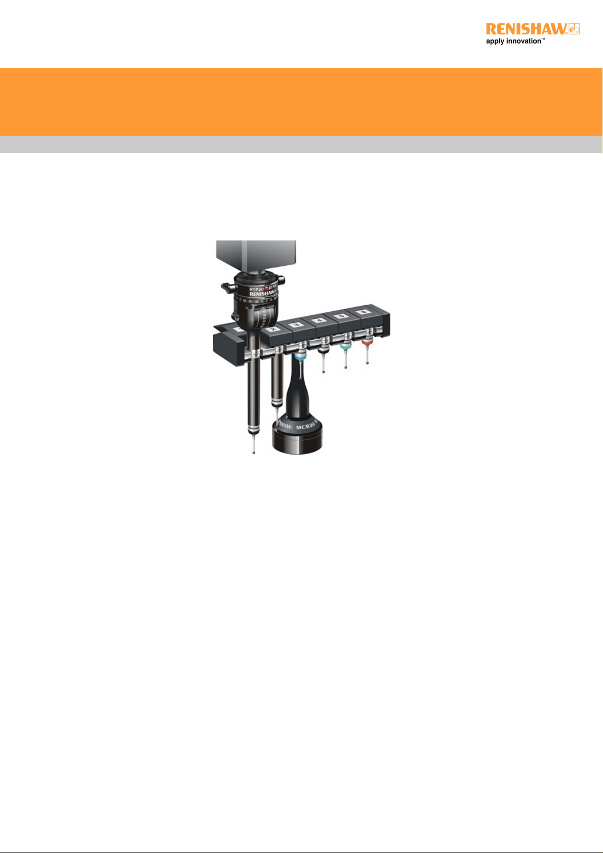
System description
RTP20isanindexableheadthatusestheCMM'smotionforrepeatablerepositioning.Itofferslowcost‘motorised'headfunctionalitywith
an integral TP20 touch-trigger probe.
Automated indexing of the head is realised through an innovative process which uses the motion of a CMM to achieve motorised head style
operation. This indexing process comprises of three operations:
An external locking lever on the probe head is driven against a dedicated sphere mounted to a pole located on the bed of the CMM, thus
unlocking the head
The CMM motion is then used to engage a drive-cup located in the head's A-axis swivel, with the pole-mounted sphere, enabling rotation
of the head in the A and B-axes by driving around the pole
The indexing operation is completed by again using the CMM motion to drive the locking lever against the pole-mounted sphere, thus
locking the head
The automated indexing of the RTP20 allows the integral TP20 probe to be moved to 168 repeatable positions in 15-degree increments
using both the A and B-axes, requiring a one-time only qualification for each stylus position thus ensuring fast throughput for part
inspection. Using the CMM motion to lock and orientate the head together with the MCR20 change rack, which allows repeatable
interchange between qualified probe modules, provides a fully automated system.
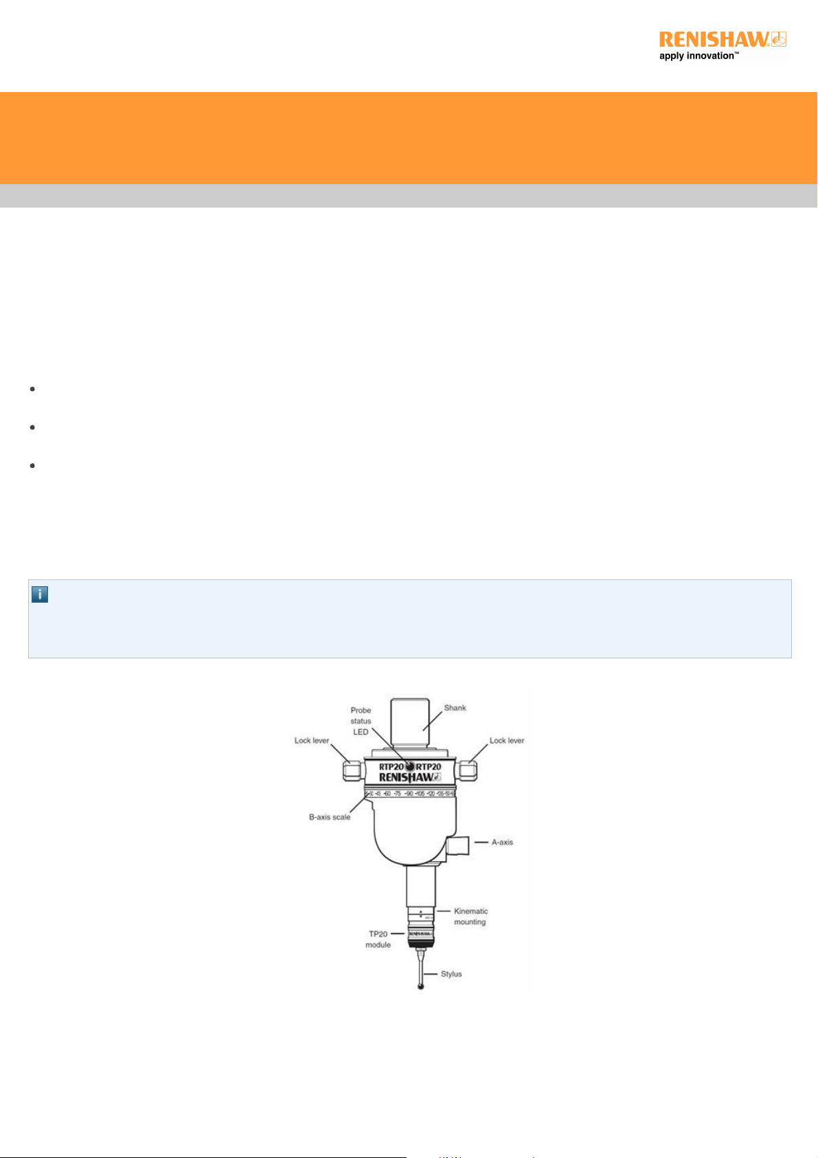
NOTE: The red LED on the front of the head indicates probe status, and can be controlled by either the CMM or a Renishaw probe
interface. Conventionally LED ON indicates probe seated (armed), and LED OFF indicates probe triggered.
Electrical connection is via a 5 pin DIN connector.
RTP20 user's guide
http://www.renishaw.com
Issued 09 2014
5
Page 6

RTP20
Specification
Measuring performance
Positionalrepeatability(2σ) 2μm(0.00008in)
(At stylus tip with TP20 standard force module and 10 mm (0.39 in) stylus length)
Positionalrepeatability(2σ) 3μm(0.00012in)
(At stylus tip with EM2 94.5 mm (3.72 in) extended module and stylus 10 mm (0.39 in) long).
Technical data
Range of articulation A-axis 0°to90°in15°increments
Range of articulation B-axis ±180°in15°increments
Dual axis lock Via lock lever
Head mounting MS range of shanks
Cable connection 5-pin DIN socket
Cable length 50 m with (24 awg) conductors
Probe status indication 1 LED
Maximum load module EM2 - 94.5 mm (3.72 in) extended
Operating temperature range +10°Cto+40°C(+50°to+104°F)
Storage temperature range 10°Cto+70°C(+14°to+158°F)
Probe module mounting TP20 kinematic
Weight - without shank 208 g
RTP20 user's guide
http://www.renishaw.com
Issued 09 2014
6
Page 7
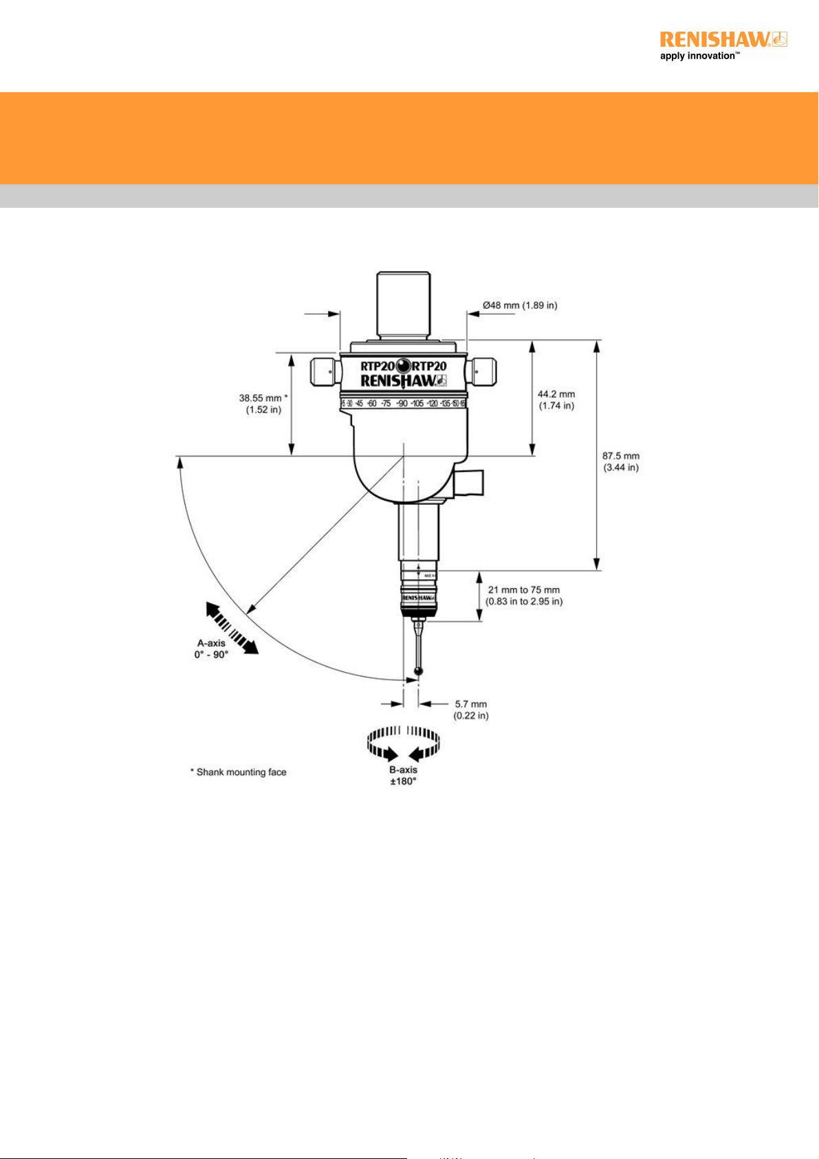
Dimensions
RTP20 user's guide
http://www.renishaw.com
Issued 09 2014
7
Page 8

Installation
Mounting the shank on the probe head
NOTE: The RTP20 shanks are factory fitted and are selected by part number when ordering (see 'Parts list').
Hold the shank in the recess on the top face of the RTP20
Rotate the shank until the four screw holes are aligned
FixtheshankinplaceusingonlyM3×5mmscrews(supplied)
Progressively tighten with the 2.5 mm A/F hexagonal key (supplied)
Mounting the RTP20 to the CMM
The head is normally attached to the CMM quill using a shank to suit it.
For optimum shielding against EM phenomena, it is recommended that the shank is grounded to the same electrical point as the control
system.
Custom designed mountings are available, subject to approval from Renishaw's Custom Products Department. Please contact your
supplier or Renishaw for further information.
The head mounting must be rigid, as any movement during operation will introduce system measurement errors. If the head is replaced or
repositioned in the quill, all head positions in current use must be requalified before making further measurements.
NOTE: Remove plastic cap from kinematic mount prior to attaching a TP20 module. Keep in a safe place for future protection.
RTP20 user's guide
http://www.renishaw.com
Issued 09 2014
8
Page 9
Operation
WARNING: Safety glasses should be worn and the CMM speed be reduced during initial operation of RTP20.
It is the machine supplier's responsibility to ensure that the user is made aware of any hazards involved in operation, including those
mentioned in Renishaw product documentation, and to ensure that adequate guards and safety interlocks are provided.
CAUTION: RTP20 is designed for automated operation under direct control of the CMM software. To avoid possible collision during
use, RTP20 must not be unlocked, re-orientated or locked by hand during normal operation.
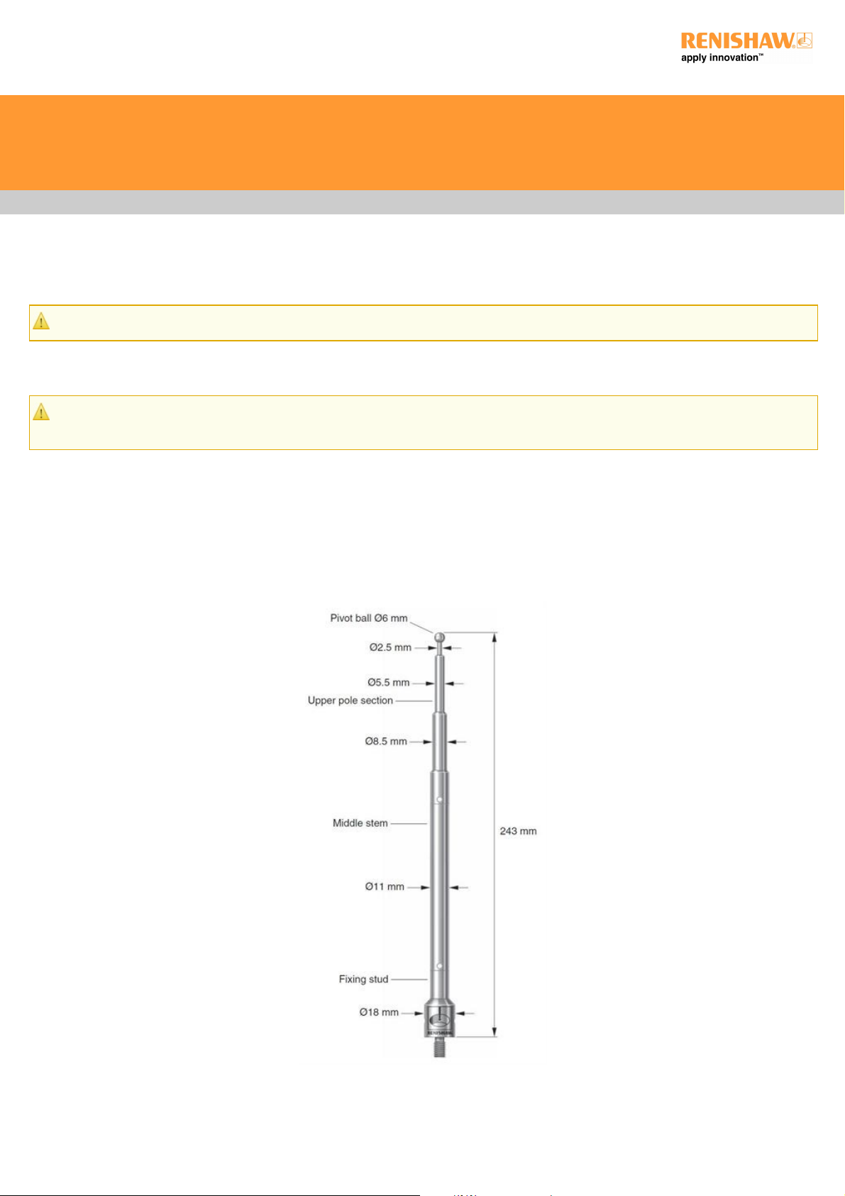
Preparing RTP20 for use
To prepare RTP20 for use, the pivot pole must be correctly fitted to the CMM table to ensure unobstructed operation of the probe head. The
pole consists of three sections; a fixing stud, middle stem and upper pole section which has the pivot sphere at its tip. The pole sections
must be fitted using the torque tool (supplied) to ensure the pole does not become loose during operation. Various fixing studs are available
fordifferentCMMtablefixtureholes,theseare;M6x1,M8x1.25,M10x1.5,5/16”xUNCand3/8”xUNC.
RTP20 user's guide
http://www.renishaw.com
Issued 09 2014
9
Page 10

CAUTION: RTP20 must be locked in the A, 0 and B, 0 position before initially defining the pivot pole sphere.
Prior to initial use, RTP20 is locked in the A, 0 and B, 0 position to enable the OEM supplied software to define the pivot pole sphere
location at eight default positions for RTP20. This is done by calibrating four angles in the A-axis and four angles in the B-axis. Whilst a
small degree of misalignment can be accommodated by head/cup geometry, this should be minimised where possible and the first moves
should be carried out slowly to confirm clearances.
Using RTP20
To change the orientation of RTP20:
1. UsetheOEMsuppliedRTP20software‘macro'tosendtheheadtoasafety‘standoff'positionthatoffersaclearpathtothepivotpole
sphere.
2. Fromthis‘standoff'position,sendRTP20tothesphereusingtheCMMaxestolocateandrotatetheappropriateleftorrighthand
locking lever of the head to unlock it. The head is then repositioned to engage the RTP20 cup on the pivot pole sphere to index it to the
required angle. Once the required angle is reached, the cup is disengaged from the pole sphere and the head is moved to locate and
rotate the appropriate locking lever to the re-locked condition.
3. RTP20isthenreturnedtoasafety‘standoff'positionclearofthepivotpole.
4. Commence gauging, ensuring that the correct qualification data is recalled for each head position.
To define RTP20 probe head positions:
UsetheOEMsuppliedRTP20software‘macro'tochangetheorientationoftheprobetothenextdesiredpositionandqualifythestylus
tip(s)
Qualify the stylus tip(s) according to the CMM supplier's instructions
Repeat the qualification process for all other desired orientations and stylus tips
Periodic re-qualification should be performed under the following circumstances:
CMM supplier's recommendations, particularly in respect of temperature changes
At the start of the working day or shift
After an accidental collision
After changing any measuring system component (except a prequalified TP20 module)
If the initial state is unknown or uncertain
RTP20 user's guide
http://www.renishaw.com
Issued 09 2014
10
Page 11

TP20 probe modules
This section covers the use and care of the TP20 probe modules for the RTP20.
Introduction
The Renishaw TP20 probe modules incorporate a kinematic coupling, which ensures highly repeatable stylus tip positioning.
The range of modules comprises 5-way versions with length or trigger force options and a 6-way version.
Probe modules fit directly onto the RTP20 kinematic mount. It is possible to change TP20 modules with different stylus configurations
without re-qualification.
Specification
Product compatibility The TP20 is suitable for use with all Renishaw probe interfaces and probe heads which service the TP2
and TP6 touch-trigger probes.
Diameter 13.2 mm
Length:
LF / SF / MF / EF 38 mm
EM1 STD 88 mm
EM2 STD 113 mm
6-way 42 mm
Probe module mounting TP20 kinematic
Stylus mount ThreadM2×0.4
Sense directions:
LF / SF / MF / EF / EM1 STD /
EM2 STD
5way(±X,±Y,+Z)
6-way 6way(±X,±Y,±Z)
Probe module pull-off force 10 N (1 kgf), 36 ozf maximum
Sealing IP30
Probe module life 25,000 changes
RTP20 user's guide
http://www.renishaw.com
Issued 09 2014
11
Page 12

Probe module type and stylus length
Parameter LF SF MF EF 6-way EM1 STD EM2 STD
Stylus length 10 mm 10 mm 25 mm 50 mm 10 mm 10 mm 10 mm
Trigger force
(nominal at stylus tip) XY
0.055 N
(5.5 gf)
0.08 N
(8 gf)
0.1 N
(10 gf)
0.1 N
(10 gf)
0.14 N
(14 gf)
0.08 N
(8 gf)
0.08 N
(8 gf)
Trigger force
(nominal at stylus tip) Z
0.65 N
(65 gf)
0.75 N
(75 gf)
1.9 N
(190 gf)
3.2 N
(320 gf)
1.6 N
(160 gf)
0.75 N
(75 gf)
0.75 N
(75 gf)
Overtravel force
(max. at stylus tip) XY
0.09 N
(9 gf)
0.2 N - 0.3 N
(20 gf - 30 gf)
0.2 N - 0.4 N
(20 gf - 40 gf)
0.2 N - 0.5 N
(20 gf - 50 gf)
0.25 N
(25 gf)
0.2 N - 0.3 N
(20 gf - 30 gf)
0.2 N - 0.3 N
(20 gf - 30 gf)
Overtravel force
(max. at stylus tip) +Z
1.1 N
(115 gf)
3.5 N
(350 gf)
7 N
(700 gf)
10 N
(1 kgf)
2.5 N
(250 gf)
3.5 N
(350 gf)
3.5 N
(350 gf)
Overtravel force
(max. at stylus tip) -Z
- - - - 9 N
(900 gf)
- -
Overtravel displacement XY* ±14° ±14° ±14° ±14° ±14° ±14° ±14°
Overtravel displacement +Z 3.1 mm 4 mm 3.7 mm 2.4 mm 4.5 mm 4 mm 4 mm
Overtravel displacement -Z - - - - 1.5 mm - -
* The probe module may detach if this value is exceeded
NOTE: The use of cranked styli with RTP20 is not recommended.
Probe module changing repeatability
Probe module changing method Repeatability
Automatic changing 1μm
Manual changing 2μm
Measuring performance
NOTE: The following data is derived from high accuracy test rig measurements and may not represent the performance achievable on a
CMM. Please consult your CMM supplier for overall system accuracy information.
Performance at 10 mm stylus length:
Parameter LF SF MF EF 6-way EM1 STD EM2 STD
Unidirectionalrepeatability*(2σ) 0.35μm 0.35μm 0.50μm 0.65μm 0.8μm 0.35μm 0.35 m
2D (XY) form measurement deviation* ±0.6μm ±0.8μm ±1μm ±2μm ±1.5μm ±0.8μm ±0.8μm
* Measured at a trigger speed of 8 mm/s
Test stylus ball diameter 4 mm
RTP20 user's guide
http://www.renishaw.com
Issued 09 2014
12
Page 13

The probe module
Each probe module houses the touch-trigger mechanism that carries the stylus assembly. The module provides overtravel in the X, Y and Z
axes. The M2 stylus mounting is compatible with Renishaw's comprehensive range of M2 styli.
Electrical contact pins automatically complete the probe circuit.
TP20 module selector
Seven versions of the TP20 probe module can be used with the RTP20, they can be identified by the end cap colour.
1. Low force (LF) probe module (green cap)
2. Standard force (SF) probe module (black cap)
3. Medium force (MF) probe module (grey cap)
4. Extended force (EF) probe module (brown cap)
5. 6-way (6W) probe module (blue cap)
6. Extension module 1 standard force (EM1 STD) (black cap)
7. Extension module 2 standard force (EM2 STD) (black cap)
Medium and extended force modules are used to overcome the effects of false triggers, caused either by stylus length and mass, or
vibration caused by machine acceleration forces.
The low force module permits the measurement of delicate objects.
The EM1 and EM2 extended modules allow access to otherwise inaccessible workpiece features. Both operate using standard force and
offer better measuring performance than using long styli with SF, MF, LF or EF modules.
The TP20 6-way senses in the +Z and -Z directions, allowing undercuts to be checked.
RTP20 user's guide
http://www.renishaw.com
Issued 09 2014
13
Page 14

Module Minimum stylus length Maximum stylus length Overall reach
Low force (LF) 10 mm (0.39 in) 30 mm (1.18 in) 94 mm (3.70 in)
Standard force (SF) 10 mm (0.39 in) 50 mm (1.97 in) 114 mm (4.49 in)
Medium force (MF) 10 mm (0.39 in) 60 mm (2.36 in) 124 mm (4.88 in)
Extended force (EF) 10 mm (0.39 in) 60 mm (2.36 in) 124 mm (4.88 in)
6-way 10 mm (0.39 in) 30 mm (1.18 in) 98 mm (3.86 in)
EM1 10 mm (0.39 in) 50 mm (1.97 in) 143 mm (5.63 in)
EM2 10 mm (0.39 in) 50 mm (1.97 in) 168 mm (6.61 in)
TP20 installation
Assembling the probe module and stylus
1. Select the probe module with the correct trigger force rating for the application (see 'TP20 module selector' section).
2. Fit the stylus to the probe module, first hand tightening then using the S7 stylus tool (supplied) for final tightness. Renishaw GF styli
require an S20 spanner. The recommended tightening torque is 0.05 Nm to 0.15 Nm (0.04 lb ft to 0.11 lb ft). Torque must not exceed 0.3
Nm (0.22 lb ft).
Fitting the probe module with stylus on the RTP20
1. Examine all mating faces for cleanliness. Where necessary, clean the surfaces with the Renishaw CK200 kit (supplied).
2. The TP20 module and kinematic mount are marked with three unique alignment marks. When offering the TP20 up to the probe head,
ensure that similar marks are aligned with each other. Allow the TP20 body to engage under magnetic force.
RTP20 user's guide
http://www.renishaw.com
Issued 09 2014
14
Page 15

RTP20 user's guide
http://www.renishaw.com
Issued 09 2014
15
Page 16
The MCR20 module change rack
The MCR20 probe module changing rack kit
NOTE: Renishaw supplies eight types of MCR20 probe module changing rack kit, each kit providing a different combination of probe
modules. See 'The MCR20 module change rack' for the range of kits offered.
The MCR20 probe module changing rack kit comprises the following primary components:
One Renishaw MCR20 probe module changing rack
One Renishaw SCR200 mounting kit
One location piece
One Renishaw PS2R stylus
Two Renishaw TP20 probe modules (probe module combination supplied will depend on part number of kit)
The MCR20 probe module changing rack, which can be easily mounted onto a CMM using the Renishaw SCR200 mounting kit and
location piece, is designed to securely hold stored probe modules for automatic changing, and to protect these stored probe modules from
airborne contaminants that may be present within the working environment. Only seven datum points are needed to set the MCR20 rack
alignment and probe module changing co-ordinates.
When using the rack, the inhibit version of the TP20 probe must be used. By generating a magnetic field about the front of each docking
port lid, the MCR20 effectively 'closes' the probe's inhibit switch during a probe module changing cycle. Rack function is completely passive
and no electrical input is required.
During automatic changing of probe modules, limited crash protection is provided by hinged overtravel mechanisms incorporated within
both the base and the docking port assembly of the MCR20. Provided any collision occurs in the direction of overtravel, the hinged
overtravel mechanisms can be manually reset and normally it should not be necessary to re-datum the rack.
MCR20 probe module changing rack kits are available with the following combinations of probe modules and may be ordered from your
supplier:
RTP20 user's guide
http://www.renishaw.com
Issued 09 2014
16
Page 17
MCR20 probe kit number LF SF MF EF Part number
1 2 A-1371-0261
2 1 1 A-1371-0262
3 1 1 A-1371-0263
4 2 A-1371-0264
5 1 1 A-1371-0265
6 2 A-1371-0266
7 1 1 A-1371-0267
8 1 1 A-1371-0268
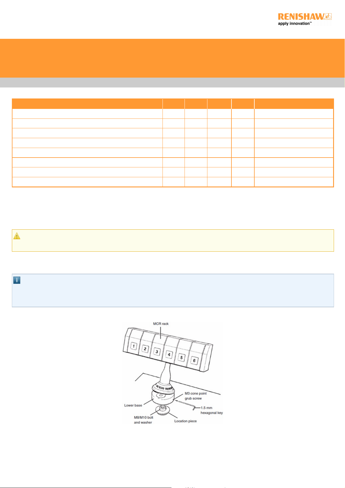
Mounting the MCR20 onto the CMM
To mount the MCR20 probe module change rack onto your CMM, carry out the following procedure:
CAUTION: For optimum crash protection, it is recommended that the MCR20 is mounted as close as possible to the extreme edge
of the CMM operating envelope.
1. Place the location piece in the desired position on the CMM table and secure in place using the M8 / M10 bolt and washer supplied.
Using the appropriate Allen key (supplied), fully hand-tighten the M8 / M10 bolt into the threaded insert within the CMM table.
NOTES: Whilst the TP20 system does not require that the MCR20 is aligned with the CMM axes, ease of programming or software
constraints may make alignment with the CMM axes desirable.
The MCR20 is not designed for horizontal operation with the ports in a vertical orientation.
2. Mount the lower base of the MCR20 probe module change rack over the location piece and rotate the X-axis of the rack until the
required alignment is obtained.
3. Using the 1.5 mm hexagonal key supplied, fully hand-tighten the M3 cone point grubscrew (0.5 Nm to 1 Nm) to lock the MCR20 in
position.
RTP20 user's guide
http://www.renishaw.com
Issued 09 2014
17
Page 18

WARNINGS: The use of eye protection is recommended.
Pinch hazards exist between parts and between moving and static parts. Beware of unexpected movement. You should remain
outside the full working envelope of probe head/extension bar/probe combinations.
It is the machine supplier's responsibility to ensure that the user is made aware of any hazards involved in operation, including those
mentioned in Renishaw product documentation, and to ensure that adequate guards and safety interlocks are provided.
Under certain circumstances, the probe signal may falsely indicate a probe seated condition. Do not rely on probe signals to stop the
machine.
NOTES: Renishaw recommends that datuming of the MCR20 is performed using the Renishaw PS2R stylus supplied. If a different
stylus is to be used, the length (L) must be either 20 mm or 30 mm and the appropriate ball radius (R) must be used to calculate
offsets.
It is strongly recommended that the EM1 STD and EM2 STD probe extension modules are not used for datuming of the MCR20, as
the extended probe length may lead to increased concentricity errors within the probe system.
The following instructions assume that uncompensated probing points are taken, and therefore that the target positions for port
docking are absolute machine co-ordinates.
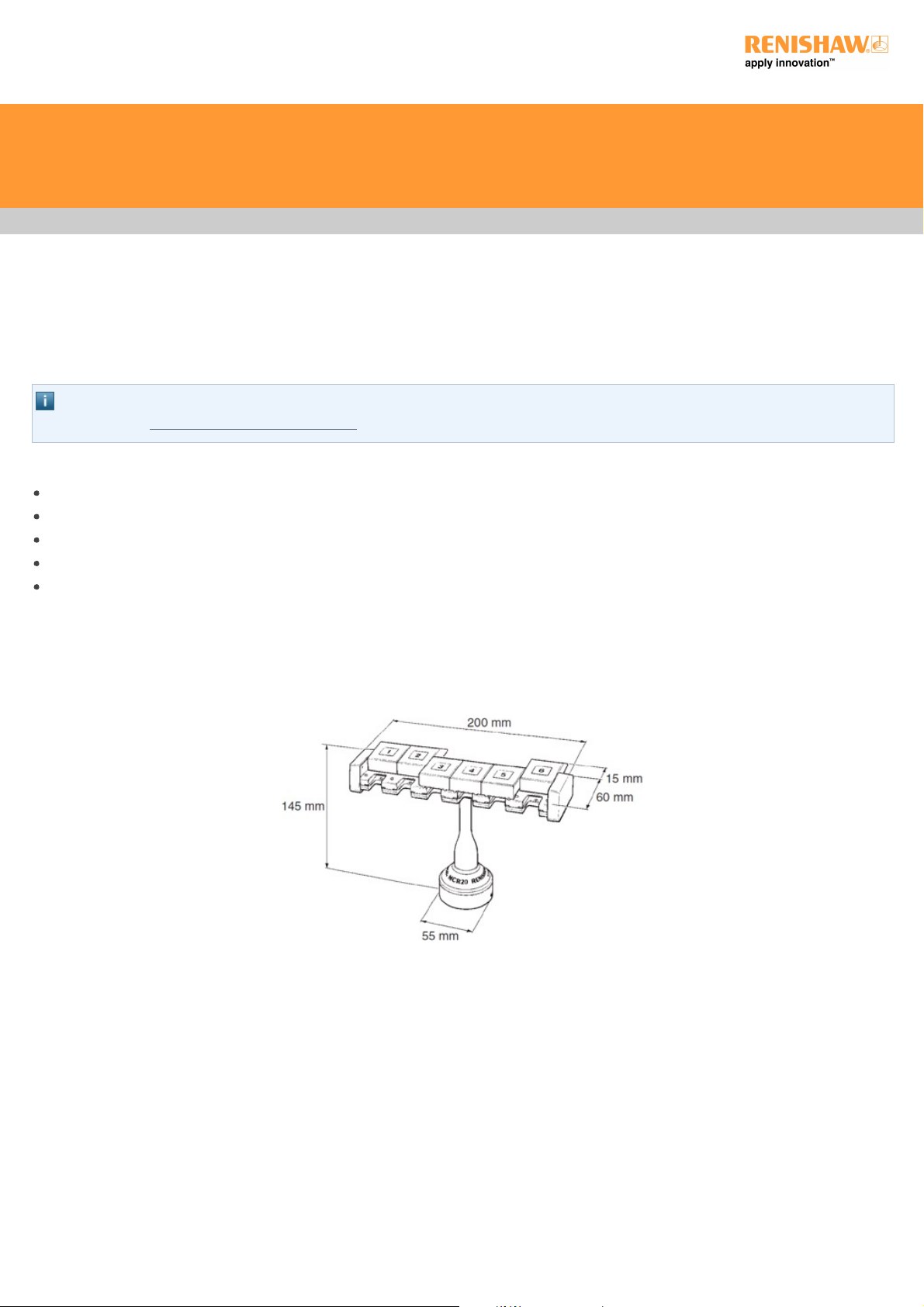
Dimensions:
Length 200 mm
Width 60 mm
Height 145 mm
Port entry velocity Maximum 800 mm/s
Mounting orientation Not designed for horizontal operation with the ports in a vertical orientation
Y-axis overtravel Hinged breakout from base
55 mm travel at port height
Z-axis overtravel Hinged docking port assembly
90°travelin–Zaxis
Inhibit range 100 mm from port centre
RTP20 user's guide
http://www.renishaw.com
Issued 09 2014
18
Page 19

Fault finding
RTP20
CAUTION: RTP20 is designed for automated operation under direct control of the CMM software. To avoid possible collision during
use, RTP20 must not be unlocked, re-orientated or locked by hand during normal operation.
Poor measuring performance
Possible causes Remedy
Loose mounting Ensure shank mounting screws are tight and mounting to CMM is secure.
Problem with TP20 probe
module
Diagnosis of the probe unit should be carried out with axes correctly locked an without head adjustment
between probe points.
Problem with swivelling /
indexing unit
Diagnosis of the indexing unit should only be carried out following satisfactory probe performance.
No probe signal and / or no probe status LED
Possible causes Remedy
Cable faulty / not connected Check continuity of cabling from head to interface / machine control.
Probe interface faulty / not connected Ensure correct connection of interface / machine control.
Poor repeatability (RTP20 only)
Possible causes Remedy
Axes lock procedure incorrect Using automated cycle ensure lock lever is fully rotated to lock position.
Axes unlock procedure incorrect Using automated cycle ensure lock lever is fully rotated into unlock position during
indexing.
Forces imparted onto head during lock-up Using automated cycle unlock and re-lock.
Attempted lockup in incorrect unqualified
position
Using automated cycle unlock, reposition correctly and re-lock.
Axes‘rattling'duringindexing(RTP20only)
Possible causes Remedy
Incorrect unlock procedure Using automated cycle ensure lock lever is fully rotated to unlock position.
Incorrect indexing procedure Using automated cycle index each axis separately.
NOTE: The RTP20 is not user serviceable and should be returned to Renishaw if suspected faulty.
RTP20 user's guide
http://www.renishaw.com
Issued 09 2014
19
Page 20

TP20
Poor measuring performance
Possible causes Remedy
Stylus configuration too long or not rigid Use shorter stiffer stylus configuration.
Poor stylus assembly Ensure stylus joints are kept to a minimum and the joints are clean and secure.
Contamination / damage to stylus ball Inspect for damage, clean thoroughly with solvent.
Trigger force too high. Use lower force module.
Unwanted triggering during probe or CMM movement
Possible causes Remedy
Trigger force too low / stylus configuration to heavy Use higher force module / reduce mass of stylus configuration.
Probe fails to rearm after trigger
Possible causes Remedy
Trigger force too low / stylus configuration too heavy Use higher force module / reduce mass of stylus configuration.
Probe reseat failure Re-trigger probe. If problem persists please return to Renishaw for service.
Loss of measuring accuracy
Possible causes Remedy
Mounting not secure Check that the RTP20 is correctly mounted on the shank and that the screws are secure.
Check clamping mechanism in the CMM quill is secure for RTP20.
RTP20 not fully locked Ensure that the thumbwheel / lock lever is turned fully clockwise.
Force imparted to probe module after locking Re-qualify the probe.
RTP20 worn or damaged Use only with the specified probe and extension combinations.
Faulty probe module Check by substitution or return to Renishaw or your supplier.
RTP20 user's guide
http://www.renishaw.com
Issued 09 2014
20
Page 21

Maintenance
Renishaw probes are intended for use in a protected metrology environment and therefore accumulation of dust or contamination should not
occur.
In common with all precision measuring equipment, regular inspection and cleaning is recommended to ensure continued high
performance.
Maintenance of the head is limited to wiping the outer surfaces and axes scale labels with a clean dry cloth or proprietary cleaning material.
Maintenance of the TP20 probe is restricted to the periodic cleaning of the kinematic couplings on the probe head and the probe module.
To aid cleaning of these couplings, the RTP20 is supplied with a Renishaw CK200 cleaning kit. Do not use any other cleaning method.
When operating the TP20 probe in environments subjected to air-borne contamination, the user should determine the frequency of cleaning
required.
RTP20 user's guide
http://www.renishaw.com
Issued 09 2014
21
Page 22

Parts list
TP20 probe modules
The RTP20 can be ordered with either LOW, STD, MED, or EXT force modules (see see 'TP20 module selector' section for details). If
additional modules are required please refer to the table below for part numbers:
Description Part number
TP20 modules
LOW A-1371-0392
STD A-1371-0270
MED A-1371-0271
EXT A-1371-0272
EM1 A-1371-0430
EM2 A-1371-0431
TP20 6-way A-1371-0419
Probe tools
S7 stylus tool kit (supplied) A-5000-7835
S20 stylus tool (not supplied) A-5003-2300
CK200 cleaning kit (supplied) A-1085-0016
Head and shank combinations
Description Part number
RTP20 pole adaptor - M8 A-5400-0121
RTP20 pole adaptor - M6 A-5400-0122
RTP20 pole adaptor - 5/16 A-5400-0123
RTP20 pole adaptor - 3/8 A-5400-0124
RTP20 pole adaptor - M10 A-5400-0125
RTP20 pole A-5400-0126
RTP20 cup replacement kit A-5400-0300
RTP20 kits Please contact your local Renishaw subsidiary
RTP20 user's guide
http://www.renishaw.com
Issued 09 2014
22
Page 23

For worldwide contact details,
please visit our main website at
www.renishaw.com/contact
Renishaw plc
New Mills, Wotton-under-Edge,
Gloucestershire, GL12 8JR
United Kingdom
T +44 (0)1453 524524
F +44 (0)1453 524901
www.renishaw.com/cmmsupport
Issued 09 2014
 Loading...