

Renishaw RSP3 Series, RSP3-1, RSP3-2, RSP3-3, RSP3-4 Installation And User Manual
...
RSP3 installation and user's guide
Document part number H-1000-5124-02-E
RSP3 installation and user's guide
www.renishaw.com
Issued 10 2019
1

General information
© 2015 ‐ 2019 Renishaw plc. All rights reserved.
This document may not be copied or reproduced in whole or in part, or transferred to any other media or language, by any means, without
the prior written permission of Renishaw.
The publication of material within this document does not imply freedom from the patent rights of Renishaw plc.
Disclaimer
RENISHAW HAS MADE CONSIDERABLE EFFORTS TO ENSURE THE CONTENT OF THIS DOCUMENT IS CORRECT AT THE DATE OF
PUBLICATION BUT MAKES NO WARRANTIES OR REPRESENTATIONS REGARDING THE CONTENT. RENISHAW EXCLUDES LIABILITY,
HOWSOEVER ARISING, FOR ANY INACCURACIES IN THIS DOCUMENT.
Trademarks
RENISHAW, the probe symbol used in the RENISHAW logo and REVO are registered trademarks of Renishaw plc in the United Kingdom and
other countries. apply innovation and names and designations of other Renishaw products and technologies are trademarks of Renishaw
plc or its subsidiaries.
All brand names and product names used in this document are trade names, service marks, trademarks, or registered trademarks of their
respective owners.
All trademarks and trade names are acknowledged.
WEEE
The use of this symbol on Renishaw products and/or accompanying documentation indicates that the product should not be mixed with the
general household waste upon disposal. It is the responsibility of the end user to dispose of this product at a designated collection point for
waste electrical and electronic equipment (WEEE) to enable reuse or recycling. Correct disposal of this product will help save valuable
resources and prevent potential negative effects on the environment. For more information, please contact your local waste disposal service
or Renishaw distributor.
Warranty
Renishaw plc warrants its equipment for a limited period (as set out in our Standard Terms and Conditions of Sale) provided that it is installed
exactly as defined in associated Renishaw documentation.
Prior consent must be obtained from Renishaw if non-Renishaw equipment (e.g. interfaces and/or cabling) is to be used or substituted. Failure
to comply with this will invalidate the Renishaw warranty.
Claims under warranty must be made from authorised service centres only, which may be advised by the supplier or distributor.
RSP3 installation and user's guide
www.renishaw.com
Issued 10 2019
2

Care of equipment
Renishaw probes and associated systems are precision tools used for obtaining precise measurements and must therefore be treated with
care.
Changes to Renishaw products
Renishaw reserves the right to improve, change or modify its hardware or software without incurring any obligations to make changes to
Renishaw equipment previously sold.
Packaging
To aid end user recycling and disposal the materials used in the different components of the packaging are stated here:
Packaging component Material 94/62/EC code 94/62/EC number
Box Polypropylene PP 05
Packing foam Polyurethane foam PUR 113
Outer box Corrugated fibreboard PAP 20
Packaging insert Corrugated fibreboard PAP 20
Bag Static dissipative coating,
polyester, aluminium shield,
static dissipative polyethylene
C/LDPE 90
Bag Low density polyethylene LDPE 4
Label Polypropylene PP 05
RSP3 installation and user's guide
www.renishaw.com
Issued 10 2019
3

Patents
Features of the RSP3 system and associated products (such as REVO-2), equipment and techniques are the subjects of one or more of the
following patents and patent applications:
CA2925301 CN100453970 EP1086352 IN259801 JP2016-533484 US2016-0238373
CN101166951 EP1086354 IN279118 JP2018-514773 US2018-0058884
CN101166953 EP1368615 IN292511 JP4062515 US6633051
CN101405563 EP1505362 IN294476 JP4695762 US6909983
CN101405564 EP1687589 IN295786 JP4726303 US7146741
CN101490430 EP1877727 IN296310 JP5196356 US7533574
CN101675317 EP1877732 WO2006/114603 JP5210536 US7809523
CN101772690 EP1989504 WO2007/107776 JP5350216 US7861430
CN102305613 EP2002206 WO2008/132490 JP5425476 US7885777
CN102906533 EP2002207 WO2011/135282 JP5555159 US7971365
CN103842766 EP2035719 WO2014/191729 JP5653581 US8006398
CN105408723 EP2140318 WO2015/049341 JP5658863 US8186882
CN105793695 EP2142880 WO2018/091867 JP5706158 US8302321
CN107532930 EP2167911 JP5851969 US8381588
EP2431707 JP6013533 US8425119
EP2564151 JP6199870 US8474148
EP2764324 JP6348577 US8511898
EP3004797 US8601701
EP3052926 US8756973
EP3289314 US8978261
US9038282
US9366519
US9903713
RSP3 installation and user's guide
www.renishaw.com
Issued 10 2019
4

Product compliance
EU declaration of conformity
Contact Renishaw plc or visit www.renishaw.com/EU for the full EU declaration.
EMC conformity
This equipment must be installed and used in accordance with this installation guide. This product is intended for industrial use only and
should not be used in a residential area or connected to a low voltage power supply network which supplies buildings used for residential
purposes.
FCC (USA only)
Information to user (47 CFR 15.105)
This equipment has been tested and found to comply with the limits for a Class A digital device, pursuant to Part 15 of the FCC rules. These
limits are designed to provide reasonable protection against harmful interference when the equipment is operated in a commercial
environment. This equipment generates, uses, and can radiate radio frequency energy and, if not installed and used in accordance with the
instruction manual, may cause harmful interference to radio communications. Operation of this equipment in a residential area is likely to
cause harmful interference, in which case you will be required to correct the interference at your own expense.
Information to user (47 CFR 15.21)
The user is cautioned that any changes or modifications not expressly approved by Renishaw plc or authorised representative could void the
user's authority to operate the equipment.
Equipment label (47 CFR 15.19)
This device complies with part 15 of the FCC Rules. Operation is subject to the following two conditions:
1. This device may not cause harmful interference.
2. This device must accept any interference received, including interference that may cause undesired operation.
RSP3 installation and user's guide
www.renishaw.com
Issued 10 2019
5

REACH regulation
Information required by Article 33﴾1﴿ of Regulation ﴾EC﴿ No. 1907/2006 ﴾“REACH”﴿ relating to products containing substances of very high
concern (SVHCs) is available at:
www.renishaw.com/REACH
China RoHS
Contact Renishaw plc or visit www.renishaw.com/ChinaRoHS for the full China RoHS tabulation.
RSP3 installation and user's guide
www.renishaw.com
Issued 10 2019
6
Safety
CAUTION: Before unpacking and installing the REVO system, the user should carefully read the safety instructions below and
ensure that they are followed at all times by all operators.
The RSP3 range of probes is only to be used with the Renishaw REVO head.
Operators must be trained in the use and application of the REVO system and accompanying products, in the context of the
machine it is fitted to, before being allowed to operate that machine.
Permanent magnets are used in some components of the REVO system and associated products. It is important to keep them away
from items which may be affected by magnetic fields, e.g. data storage systems, pacemakers and watches etc.
RSP3 LED emissions
The RSP3 range of scanning probes incorporate embedded high power LED sources and should not be used in the event of serious damage
to, or rupture of, any part of the RSP3. In such cases IMMEDIATELY disconnect the power source, remove and do not attempt to re-use the
parts. Contact your supplier for advice.
RCP TC-2 and RCP TC-3
The method of interrupting power is to disconnect the power cable or turn off the supply.
RSP3 installation and user's guide
www.renishaw.com
Issued 10 2019
7
Warnings
Beware of unexpected movement. The user should remain outside of the full working envelope of probe head and stylus. The
machine supplier should ensure the user is aware of the full working envelope of the system.
In all applications involving the use of machine tools or CMMs, eye protection is recommended.
It is the machine supplier's responsibility to ensure that the user is made aware of any hazards involved in operation, including those
mentioned in Renishaw product documentation, and to ensure that adequate guards and safety interlocks are provided.
Refer to the machine supplier's operating instructions.
The system components contain no user serviceable parts, with the exception of RCP TC-2, RCP TC-3, RCP2 and FCR25. No attempt should be
made to disassemble any part of the product. In the event of a problem please contact your supplier for assistance.
Under certain circumstances the probe signal may falsely indicate a probe-seated condition. Do not rely on probe signals to stop machine
movement.
Probe trigger override will prevent machine backing off in the event of a probe collision.
The probe joints are designed to release the probe and / or the stylus holder in the event of a crash.
This equipment is not suitable for use in a potentially explosive atmosphere.
Pinch hazards exist between parts. Do not hold the probe or probe head during movements.
It is essential for continued safety that all fuses are replaced by the correct type and rating.
REVO must be transported in Renishaw supplied packaging.
The cables must meet Renishaw specifications. Incorrect cabling could cause damage to the equipment.
RSP3 installation and user's guide
www.renishaw.com
Issued 10 2019
8

International safety instructions
BG ‐ ПРЕДУПРЕЖДЕНИЕ
Моля, обърнете на приложение 1 и прочетете инструкциите за безопасност на вашия собствен език, преди за разопаковате и
монтирате този продукт.
CZ ‐ VÝSTRAHA
Před rozbalením a instalací tohoto výrobku si přečtěte bezpečnostní pokyny ve vlastním jazyce uvedené v příloze 1.
DA - ADVARSEL
Læs sikkerhedsinstrukserne i Appendix 1 FØR udpakning og installation af dette produkt.
DE - WARNHINWEIS
Bevor Sie dieses Produkt auspacken und installieren, konsultieren Sie bitte Anhang 1 und lesen Sie die Sicherheitshinweise in Ihrer Sprache.
EL ‐ ΠΡΟΕΙΔΟΠΟΙΗΣΗ
Γυρίστε στο Κεφάλαιο 1 και διαβάστε τις οδηγίες ασφαλείας στη δική σας γλώσσα προτού ανοίξετε αυτό το προϊόν για να το
εγκαταστήσετε.
EN - WARNING
Before unpacking and installing this product, please consult Appendix 1 and read the safety instructions in your language.
ES - ADVERTENCIA
Consulte el apéndice 1 y lea las instrucciones de seguridad en su idioma antes de desempaquetar e instalar este producto.
ET - HOIATUS
Palun vaadake 1. lisa ning lugege enne selle toote lahtipakkimist ja paigaldamist ohutusjuhend läbi.
FI - VAROITUKSIA
Lue liitteessä 1 olevat omalla kielelläsi kirjoitetut turvaohjeet ennen tämän tuotteen pakkauksen avaamista ja asentamista.
FR - AVERTISSEMENT
Consulter l'annexe 1 et les instructions de sécurité dans votre propre langue avant de déballer et d'installer ce produit.
RSP3 installation and user's guide
www.renishaw.com
Issued 10 2019
9

GA - RABHADH
Téigh chuig aguisín 1 agus déan na treoracha sábháilteachta a léamh i do theanga féin le do thoil sula ndéantar an táirge seo a dhíphacáil
agus a shuiteáil.
HR - NAPOMENA
Prije nego što proizvod izvadite iz ambalaže i ugradite ga, otvorite Prilog 1 i pročitajte sigurnosne upute na svom jeziku.
HU – FIGYELMEZTETÉS
A termék kicsomagolása és telepítése előtt olvassa el az 1. számú függelékben található, az Ön anyanyelvén hozzáférhető biztonsági
utasításokat.
IT - AVVISO
Prima di aprire ed installare questo prodotto, leggere le istruzioni di sicurezza nella vostra lingua riportate nell'Appendice 1.
JA ‐ 警告
この製品を箱から取り出し設置する前に、付録 1 に記載された安全性に関する注意書きをお読みください。
LT – ĮSPĖJIMAS
Prieš išpakuodami ir įdiegdami produktą, turite grįžti prie 1 priedo ir perskaityti nurodymus dėl saugos savo kalba.
LV – BRĪDINĀJUMS
Pirms šī izstrādājuma izsaiņošanas un uzstādīšanas izskatiet 1. pielikumā sniegtās drošības instrukcijas savā valodā.
MT - TWISSIJA
Jekk jogħġbok mur f'appendiċi 1 u aqra l‐istruzzjonijiet tas‐sigurtà fil‐lingwa tiegħek qabel ma toħroġ dan il‐prodott mill‐ippakkjar u
tinstallah.
NL - WAARSCHUWING
Ga naar appendix 1 en lees de veiligheidsinstructies in uw eigen taal, voordat u dit product uitpakt en installeert.
PL ‐ OSTRZEŻENIE
Przed rozpakowaniem i zainstalowaniem tego produktu prosimy o zapoznanie się z Dodatkiem 1 i przeczytanie zaleceń dotyczących
bezpieczeństwa w danym języku.
PT ‐ ADVERTÊNCIA
Você deve retornar ao Anexo 1 e ler as instruções de segurança em seu idioma antes de desembalar e instalar este produto.
RSP3 installation and user's guide
www.renishaw.com
Issued 10 2019
10

RO - AVERTISMENT
Înainte de a desface ambalajul şi a instala acest produs, vă rugăm să căutaţi Anexa 1 şi să citiţi cu atenţie instrucţiunile de siguranță, în limba
română.
SK ‐ VÝSTRAHA
Pred rozbalením a inštaláciou tohto produktu si pozrite prílohu 1 a prečítajte si bezpečnostné pokyny vo vašom jazyku.
SL - OPOZORILO
Preden izdelek vzamete iz embalaže in ga vgradite, odprite Prilogo 1 in preberite varnostna navodila v svojem jeziku.
SV - VARNING
Gå till bilaga 1 och läs säkerhetsinstruktionerna på ditt eget språk innan du packar upp och installerar denna produkt.
TW ‐ 警告
在拆開和安裝本產品之前,請翻頁至附錄 1 閱讀母語的安全指示。
中文 — 警告
在拆包和安装本产品之前,请翻到附录1,阅读中文版安全说明。
RSP3 installation and user's guide
www.renishaw.com
Issued 10 2019
11

References and associated documents
The following Renishaw documents are referred to in this document or may be a source of further relevant information. They can easily be
acquired from Renishaw web site www.renishaw.com.
Title Document number
User's guide: REVO-2 H-1000-7590
Installation and user's guide: RSP3 H-1000-5124
Installation and user's guide: SFP2 surface finish probe H-1000-5365
User's guide: RVP H-1000-3322
Installation and user's guide: MRS modular rack system H-1000-5088
Installation guide: MRS2 modular rack system H-1000-5255
Technical specifications guide: Styli and accessories H-1000-3200
RSP3 installation and user's guide
www.renishaw.com
Issued 10 2019
12

System description
The RSP3 range of probes gives REVO users the ability to carry cranked stylus arrangements and enhanced capability for carrying long styli.
The RSP3-1 / 2 / 3 / 4 probes can be used for both 3D-scanning (X, Y, Z) and touch-trigger applications. They enable accurate scanning
measurement with effective stylus lengths ranging from 20 mm - 394 mm. The RSP3-6 probe, on the other hand, provides REVO with
enhanced capability for carrying long cranked and straight styli. RSP3-6 can be used for 2D scanning and 3D touch-trigger applications. It
carries straight extensions up to 800 mm from REVO's A-axis centre of rotation, and cranked extensions up to 600 mm from REVO's A-axis
centre of rotation.
The RSP3 range uses 3-axis scanning with fixed REVO head angles during measurement. Each probe is designed to provide optimized
accuracy and contact force over a specified stylus range. Consequently, the RSH3 stylus holders are intended to fit only with their respective
RSP3 probe.
Design principles of the RSP3 scanning probes
RSP3 uses an optical transducer sensor and a pivoting motion system similar to that found in SP25M system.
The probe's pivoting motion system has two diaphragm springs. One of the RSP3 springs allows movement in all directions whilst the other
(pivot) spring is stiff in (probe) X and Y, but allows movement in Z. Its optical transducer sensor system has two infrared light emitting diodes
that project invisible infrared beams on mirrors mounted on the pivoting moving structure within the probe. The mirrors focus the beams
back onto two position sensitive devices (PSDs) which provide signal outputs in the three probe axes: P, Q, R (converted into X, Y, Z signals by
the calibration routine).
Unlike the SP25M, the RSP3's probe and module elements are built as one.
System components overview
RSP3-1 / 2 / 3 / 4
The RSP3-1 / 2 / 3 / 4 range of probes provide REVO with 3D-scanning (X, Y, Z) touch-trigger and crank stylus capabilities.
RSP3-6
The RSP3-6 probe provides REVO with enhanced capability for carrying long cranked and straight styli. RSP3-6 can be used for both 3D
touch-trigger and 2D scanning applications.
RSH3-1 / 2 / 3 / 4 stylus holders
The RSH3-1 / 2 / 3 / 4 stylus holders are designed to fit with their respective RSP3 probe. They enable accurate scanning measurements with
effective stylus lengths ranging from 20 mm - 394 mm.
The RSH3 range of stylus holders replace the SH25 range of stylus holders for use with REVO only. The SH25 range should still be used with
SP25M.
RSP3 installation and user's guide
www.renishaw.com
Issued 10 2019
13

RSH3-6c-500 / 600 and RSH3-6-600 / 700 / 800 stylus holders
The RSH3-6 stylus holders for the RSP3-6 probe are suitable for applications requiring straight extensions up to 800 mm from REVO's A-axis
centre of rotation. The RSH3-6c stylus holders are suitable for applications requiring cranked extensions up to 600 mm from REVO's A-axis
centre of rotation.
RCP TC-2 and RCP TC-3
The thermally controlled RCP TC-2 and RCP TC-3 ports maintain stored probes at operating temperature. They are compatible with
Renishaw's MRS and MRS2 rack systems.
NOTE: RCP TC-3 is for use with RSP3-6 and SFP2 only.
RCP2
The RCP2 enables rapid and repeatable changing of RSH3-6 stylus holders. It is compatible with Renishaw's MRS and MRS2 rack systems.
FCR25 flexible change rack unit
Rapid and repeatable changing of the RSH3-1 / 2 / 3 / 4 stylus holders is possible via the FCR25 triple port change rack unit, which is
compatible with Renishaw's MRS and MRS2 rack systems.
FCR25 stand-off plate
The FCR25 stand-off plate should be used on all REVO installations to mount FCR25 ports to the MRS / MRS2 rack system.
PA25-RSH3 port adapter
PA25-RSH3 port adapters are required for automated changing of the RSH3-1 / 2 / 3 / 4 stylus holders into and out of the FCR25 rack. A
PA25-RSH3 port adapter is included in every RSH3 and RSP3 kit.
RSP3 installation and user's guide
www.renishaw.com
Issued 10 2019
14
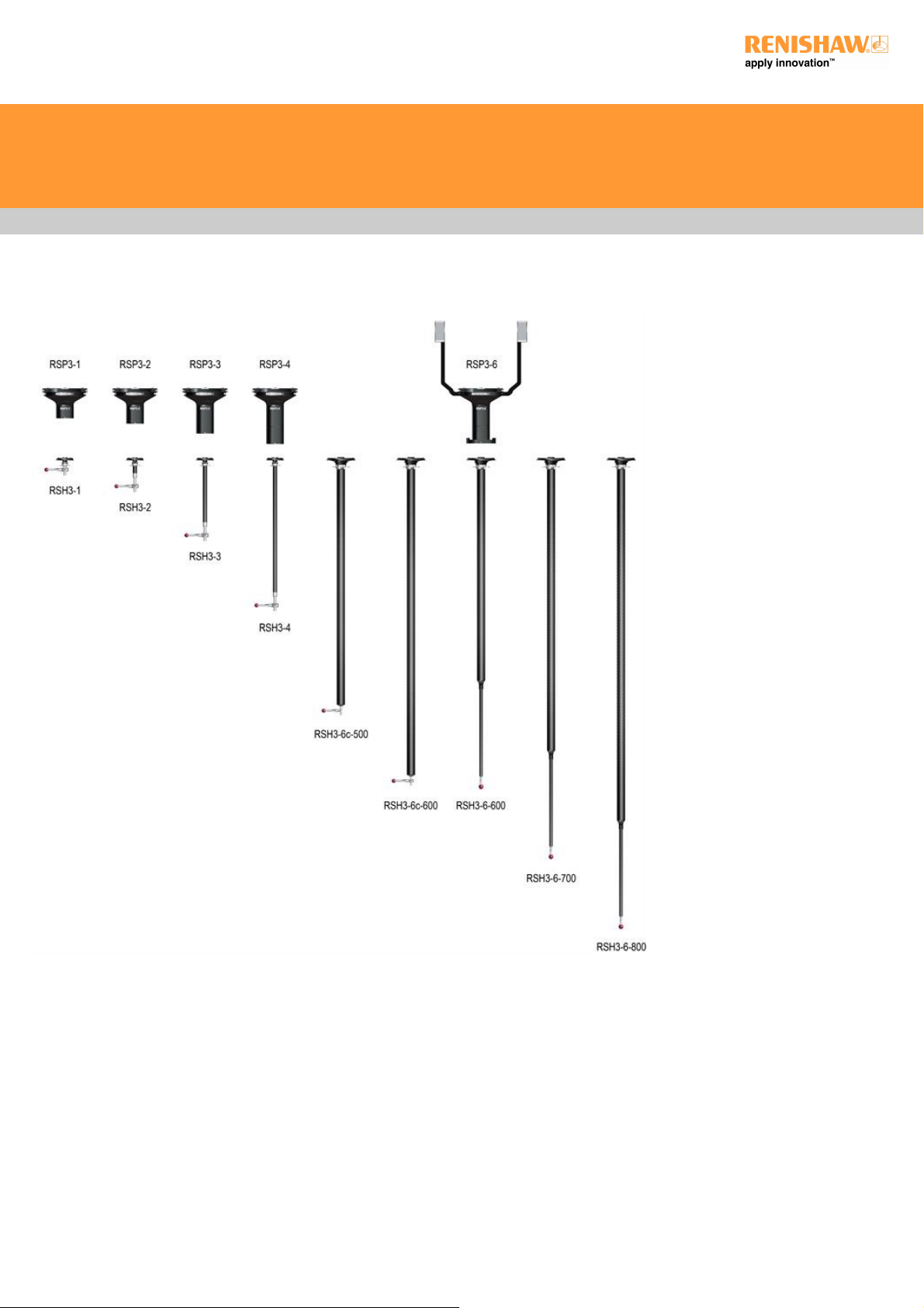
RSP3 probes and stylus holders
RSP3 installation and user's guide
www.renishaw.com
Issued 10 2019
15

Environmental and electrical specifications
Environmental specification
Operating temperature range 20 °C ±2 °C
Storage temperature range ‐10 °C to +70 °C ﴾14 °F to 158 °F﴿
Operating humidity 0% to 80% (non-condensing)
Storage humidity 0% to 80% (non-condensing)
Electrical specification
The REVO-2 head, and probe electronics and motors, are powered from the UCC S5.
The RCP TC-2 and RCP TC-3 are powered by a separate power supply that is supplied by Renishaw.
No other additional power supplies are required.
RSP3 installation and user's guide
www.renishaw.com
Issued 10 2019
16
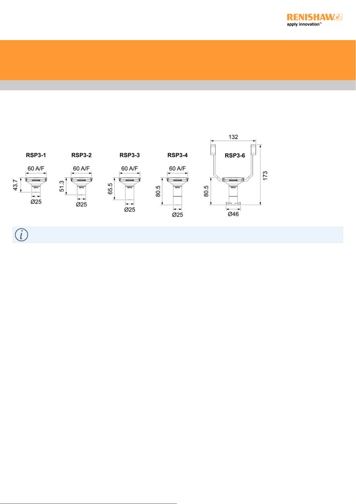
RSP3 range dimensions
NOTE: Dimensions are to the kinematic planes.
All dimensions are in mm.
RSP3 installation and user's guide
www.renishaw.com
Issued 10 2019
17

RSP3 range specifications
RSP3 installation and user's guide
www.renishaw.com
Issued 10 2019
18

RSP3-1 / 2 / 3 / 4
Characteristic Requirements
Probe attributes Scanning with 3-axis measurement (X, Y, Z) and 3-axis touch-trigger
Measurement range ±0.5 mm deflection in all directions in all orientations
Overtravel range
X, Y 2 mm
+Z 1.7 mm
-Z 1.2 mm
Resolution Capable of <0.1 μm
Spring rate Nominally 0.6 N/mm - when using shortest specified stylus
Nominally 0.2 N/mm - when using longest specified stylus
Weight
RSP3-1 86 g (3.03 oz) (excluding stylus holder and stylus)
RSP3-2 90 g (3.17 oz) (excluding stylus holder and stylus)
RSP3-3 94 g (3.32 oz) (excluding stylus holder and stylus)
RSP3-4 101 g (3.56 oz) (excluding stylus holder and stylus)
Effective stylus length range Always observe the specified stylus range for the scanning module
being used. Use Renishaw's M3 range of styli.
RSP3-1 + RSH3-1 EWL 20 mm - 50 mm (0.79 in - 1.97 in) using 20 mm - 50 mm stylus
RSP3-2 + RSH3-2 EWL 44 mm - 99 mm (1.73 in - 3.90 in) using 20 mm - 75 mm stylus
RSP3-3 + RSH3-3 EWL 114 mm - 194 mm (4.49 in - 7.64 in) using 20 mm - 100 mm
stylus
RSP3-4 + RSH3-4 EWL 214 mm - 394 mm (7.64 in - 15.51 in) using 20 mm - 200 mm
stylus
Mounting Magnetised kinematic coupling
Crash protection
±X, ±Y, ‐Z Via break out of probe or stylus holder
+Z Via integral bump-stop design
Signal outputs Non-linear and non-orthogonal analogue outputs - rate gain and
resolution are not fixed
Change rack options
RCP TC-2 Thermally controlled change port for probe changing only
This single port unit mounts on the MRS / MRS2 rack
FCR25 with FCR25 front spacer kit Triple port unit which mounts on the MRS / MRS2 rack
Interface options UCC S5
RSP3 installation and user's guide
www.renishaw.com
Issued 10 2019
19
RSP3-6
Characteristic Requirements
Probe attributes 2-axis scanning (X,Y) and 3-axis touch-trigger (X,Y,Z)
Measurement range ±0.5 mm deflection in all directions in all orientations
Overtravel range
X, Y 2 mm
+Z 1.7 mm
-Z 1.2 mm
Resolution Capable of <0.1 μm
Weight 300 g (10.58 oz) (excluding stylus holder and stylus)
Effective stylus length range
RSP3-6 + RSH3-6c-500 EWL 348 mm (13.70 in) using M2 star centre
RSP3-6 + RSH3-6c-600 EWL 448 mm (17.64 in) using M2 star centre
RSP3-6 + RSH3-6-600 EWL 456 mm (17.95 in) using 10 mm stylus
RSP3-6 + RSH3-6-700 EWL 556 mm (21.89 in) using 10 mm stylus
RSP3-6 + RSH3-6-800 EWL 656 mm (25.83 in) using 10 mm stylus
Mounting Magnetised kinematic coupling
Crash protection
±X, ±Y, ‐Z Via break out of probe or stylus holder
+Z Via integral bump-stop design
Change rack options
RCP TC-3 Thermally controlled change port for probe changing only
This single port unit mounts on the MRS / MRS2 rack
RCP2 For stylus holder changing only
This single port unit mounts to the MRS or MRS2
Interface options UCC S5
RSP3 installation and user's guide
www.renishaw.com
Issued 10 2019
20

RSP3 stylus carrying capability
The RSP3 range of probes have been optimised to give the best possible performance over a broad range of stylus and crank lengths. Each
probe within the range has a recommend effective working length over which it is able maintain a low contact force and give exceptional
scanning performance. It is therefore important to adhere to the stylus carrying recommendations given.
The use of Renishaw's range of styli and accessories is advised.
RSP3 installation and user's guide
www.renishaw.com
Issued 10 2019
21

RSP3 straight stylus carrying capability
Probe/ stylus holder Effective stylus reach (by
using these stylus lengths)
Maximum permissible stylus
length vs (mass)
Maximum operating stylus tip
deflection for above in any
orientation
RSP3-1 / RSH3-1 20 mm - 50 mm
(20 mm - 50 mm)
20 mm (7 g)
30 mm (10 g)
40 mm (13 g)
50 mm (14 g)
0.5 mm
RSP3-2 / RSH3-2 44 mm - 99 mm
(20 mm - 75 mm)
20 mm (2.5 g)
40 mm (7.5 g)
50 mm (9.5 g)
75 mm (10.5 g)
0.5 mm
RSP3-3 / RSH3-3 114 mm - 194 mm
(20 mm - 100 mm)
20 mm (8 g)
50 mm (9 g)
75 mm (10 g)
100 mm (10 g)
0.5 mm
RSP3-4 / RSH3-4 214 mm - 394 mm
(20 mm - 200 mm)
20 mm (7.5 g)
100 mm (8.5 g)
150 mm (9 g)
200 mm (9 g)
0.5 mm
RSP3-6 / RSH3-6c-500 348 mm (M2 star centre)* n/a 0.5 mm
RSP3-6 / RSH3-6c-600 448 mm (M2 star centre)* n/a 0.5 mm
RSP3-6 / RSH3-6-600 456 mm (10 mm) 10 mm (3.42 g) 0.5 mm
RSP3-6 / RSH3-6-700 556 mm (10 mm) 10 mm (3.42 g) 0.5 mm
RSP3-6 / RSH3-6-800 656 mm (10 mm) 10 mm (3.42 g) 0.5 mm
* Straight styli may be added to the RSH3-6c stylus holders.
RSP3 installation and user's guide
www.renishaw.com
Issued 10 2019
22

RSP3 cranked stylus carrying capability for typical stylus combinations
Each RSP3 probe has been optimised for maximum flexibility and sensor performance over a specific stylus range and with different crank
carrying capabilities in mind.
Please refer to Renishaw's stylus catalogue for full details of cranked and star stylus configurations that are available. It is recommended that
a 'one piece' star stylus is used wherever possible to help minimise mass. However, greater flexibility is possible by configuring a star centre
together with one or more cranked styli. Users must be sure that the overall mass of the star centre together with its multiple cranked styli
does not exceeded the recommendations found in the table below.
Straight 'down' styli can be added to RSH3-1 / 2 / 3 / 4 stylus holders below the crank centre to continue the projection 'down' from the
stylus holder, providing that the maximum overall stylus length and mass for that stylus holder is not exceeded.
RSP3 installation and user's guide
www.renishaw.com
Issued 10 2019
23
The table below provides user information for building typical RSP3 stylus and crank combinations:
Probe / stylus holder 'Crank down'
distance using
an extension
between the
stylus holder
and the crank
centre
3D scanning
maximum
'crank out'
distance when
measured to tip
of crank (star)
stylus
2D scanning
and point
taking
maximum
'crank out'
distance when
measured to tip
of crank (star)
stylus
Maximum
'down' stylus
('effective
stylus reach' see straight
styli)
Maximum
permissible
mass of crank
(star) centre
plus all styli
Maximum
operating
stylus tip
deflection for
above in any
orientation
RSP3-1/ RSH3-1 25 mm* 28 mm 58 mm 50 mm 9 g*** 0.4 mm
RSP3-1/ RSH3-1 55 mm* 28 mm 58 mm 50 mm 9 g**** 0.4 mm
RSP3-2/ RSH3-2 49 mm* 28 mm 83 mm 99 mm 6 g*** 0.4 mm
RSP3-2/ RSH3-2 79 mm* 28 mm 83 mm 99 mm 7 g**** 0.4 mm
RSP3-3/ RSH3-3 99 mm** 58 mm 83 mm 194 mm 12 g 0.4 mm
RSP3-3/ RSH3-3 119 mm 58 mm 83 mm 194 mm 11 g*** 0.4 mm
RSP3-3/ RSH3-3 149 mm 58 mm 83 mm 194 mm 10 g**** 0.4 mm
RSP3-4/ RSH3-4 199 mm** 58 mm 83 mm 394 mm 11 g 0.4 mm
RSP3-4/ RSH3-4 219 mm 58 mm 83 mm 394 mm 10 g*** 0.4 mm
RSP3-4/ RSH3-4 249 mm 58 mm 83 mm 394 mm 8 g**** 0.4 mm
RSP3-6/ RSH3-6c-500 348 mm n/a 50 mm 348 mm 8 g 0.4 mm
RSP3-6/ RSH3-6c-600 448 mm n/a 50 mm 448 mm 4.6 g 0.4 mm
* A 20 mm or longer (M3) extension must be used between the RSH3-
1 / RSH3-2 and the crank centre to give the correct 'crank down'
distance
** The crank centre may be mounted directly to the RSH3-3 / RSH3-4
or to an (M3) extension
*** This excludes the mass of the 20 mm extension
**** This excludes the mass of the 50 mm extension
***** This includes the crank down extension mass
RSP3 installation and user's guide
www.renishaw.com
Issued 10 2019
24

Probe / stylus holder 'Crank down'
distance using
an extension
between the
stylus holder
and crank
centre
(by using this
extension
length)
Maximum
permissible
crank stylus
length (3D
scanning)
Maximum
permissible
crank stylus
length (2D scan
/ point taking)
Maximum
effective stylus
reach (straight
stylus)
Maximum
permissible
mass of stylus
centre plus all
styli
Maximum
operating
stylus tip
deflection in
any orientation
RSP3-1 / RSH3-1 25 mm* (20 mm) 21 mm 50 mm 50 mm 9 g*** 0.4 mm
RSP3-1 / RSH3-1 55 mm* (50 mm) 21 mm 50 mm 50 mm 9 g**** 0.4 mm
RSP3-2 / RSH3-2 49 mm* (20 mm) 21 mm 75 mm 99 mm 6 g*** 0.4 mm
RSP3-2 / RSH3-2 79 mm* (50 mm) 21 mm 75 mm 99 mm 7 g**** 0.4 mm
RSP3-3 / RSH3-3 99 mm** (n/a) 50 mm 75 mm 194 mm 12 g 0.4 mm
RSP3-3 / RSH3-3 119 mm (20
mm)
50 mm 75 mm 194 mm 11 g*** 0.4 mm
RSP3-3 / RSH3-3 149 mm (50
mm)
50 mm 75 mm 194 mm 10 g**** 0.4 mm
RSP3-4 / RSH3-4 199 mm** (n/a) 50 mm 75 mm 394 mm 11 g 0.4 mm
RSP3-4 / RSH3-4 219 mm (20
mm)
50 mm 75 mm 394 mm 10 g*** 0.4 mm
RSP3-4 / RSH3-4 249 mm (50
mm)
50 mm 75 mm 394 mm 8 g**** 0.4 mm
RSP3-6 / RSH3-6c-500 348 mm (n/a) n/a 50 mm 348 mm 8 g 0.4 mm
RSP3-6 / RSH3-6c-600 448 mm (n/a) n/a 50 mm 448 mm 4.6 g 0.4 mm
RSP3-6 / RSH3-6-600 n/a n/a n/a 466 mm n/a n/a
RSP3-6 / RSH3-6-700 n/a n/a n/a 566 mm n/a n/a
RSP3-6 / RSH3-6-800 n/a n/a n/a 666 mm n/a n/a
* A 20 mm or longer (M3) extension must be used between the RSH3-
1 / RSH3-2 and the crank centre to give the correct 'crank down'
distance
** The crank centre may be mounted directly to the RSH3-3 / RSH3-4
or to an (M3) extension
*** This excludes the mass of the 20 mm extension
**** This excludes the mass of the 50 mm extension
***** This includes the crank down extension mass
RSP3 installation and user's guide
www.renishaw.com
Issued 10 2019
25
Manually mounting / removing the stylus holders from RSP3 probes
The range of RSH3 stylus holders have a kinematic coupling to the RSP3 probes, which provides a repeatable connection that eliminates the
need for probe requalification after a change. The change can be carried out either manually, or fully automatically by using the FCR25 flexible
change rack (for RSH3-1 / 2 / 3 / 4) or RCP2 (for the RSH3-6 range). The RSH3 stylus holders are designed to only to fit with their respective
scanning module. Incorrect combinations are prevented by the orientation ball in the kinematics.
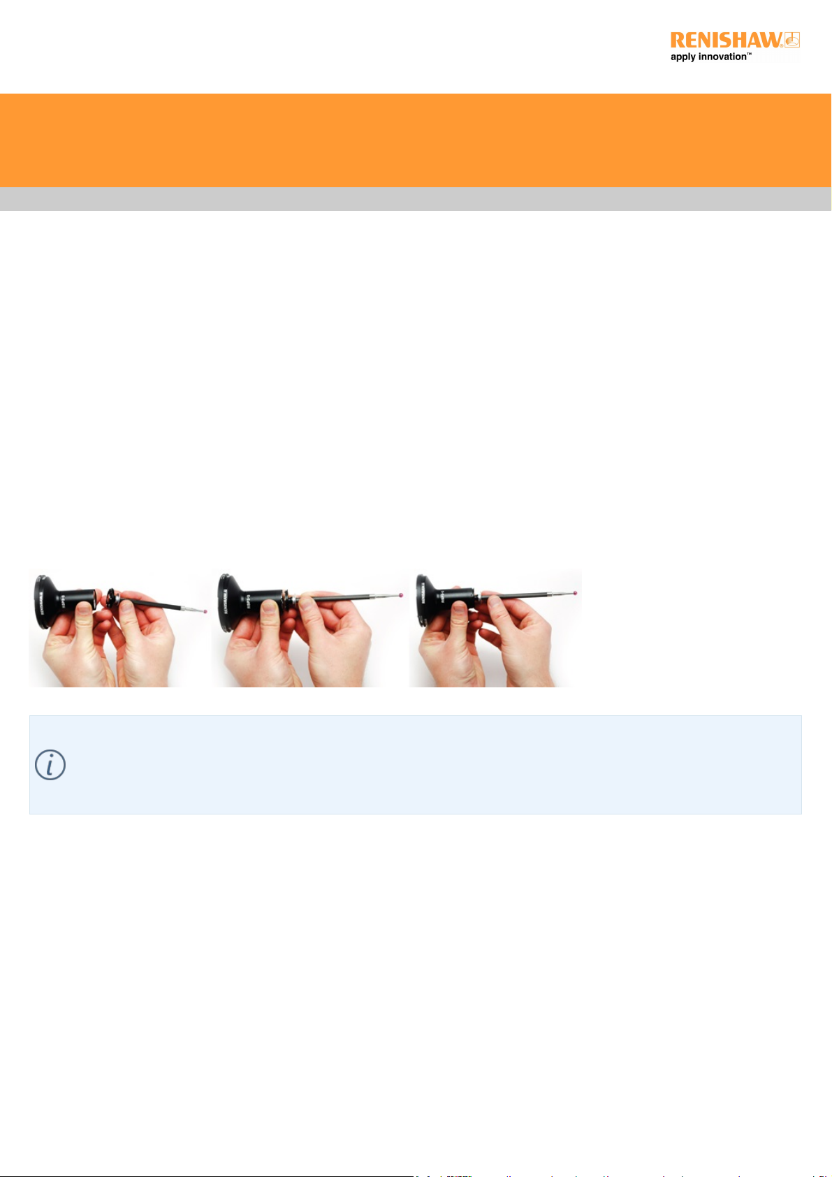
To manually mount or remove the stylus holder from the RSP3 probe you need to:
1. Align the front sides of the probe with the stylus (making sure that the alignment marks line up).
2. Carefully align the stylus holder and the probe, allowing the magnetic attraction to gently connect the kinematic joints.
3. Gently rotate the stylus holder to ensure correct location.
4. To remove, securely hold the probe, gently tilt the stylus holder to break the kinematic joints.
The REVO probe change system is designed to allow automatic REVO probe and stylus holder changing on a CMM. The primary
purpose of the system is to improve flexibility with the ability to use and store longer styli and large star stylus configurations.
For optimum metrology, REVO probes and stylus holders should be changed automatically using REVO change ports (RCP TC-2,
RCP TC-3 and RCP2) and a flexible change rack (FCR25). These ports are mounted on the modular rack system (MRS2).
RSP3 installation and user's guide
www.renishaw.com
Issued 10 2019
26
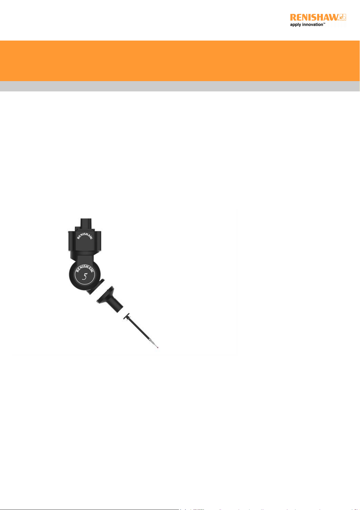
Manually mounting / removing the probes from REVO
To manually mount or remove the probe from the REVO head you need to:
1. Align the front sides of the head with the probe (look at the "Renishaw" engraving on the side of probe or alignment marks as applicable).
2. Carefully align the probe to the head, allowing the magnetic attraction to gently connect the kinematic joints.
3. Gently rotate the probe to ensure correct location.
4. To remove, securely hold the probe and gently tilt to break the kinematic joints.
RSP3 installation and user's guide
www.renishaw.com
Issued 10 2019
27
Manually mounting / removing styli from stylus holders
To manually mount or remove the stylus from a stylus holder:
1. The stylus holder must be removed from the module before mounting / removing a stylus.
2. Always stay within the recommended stylus capability range (see RSP3 stylus carrying capability guidelines).
3. Avoid touching the joint face on the stylus holder, as it may become dirty or contaminated.
4. Always use the correct stylus tools to tighten the threaded joints between the stylus and the stylus holder, thus avoiding excess torque
(causing the tool to bend).
5. To remove a stylus, reverse the above procedure.
NOTE: If a spare stylus removal tool is needed please order Renishaw part A-5000-7835 (the set comprises two S7 stylus tools in a
plastic box).
RSP3 installation and user's guide
www.renishaw.com
Issued 10 2019
28
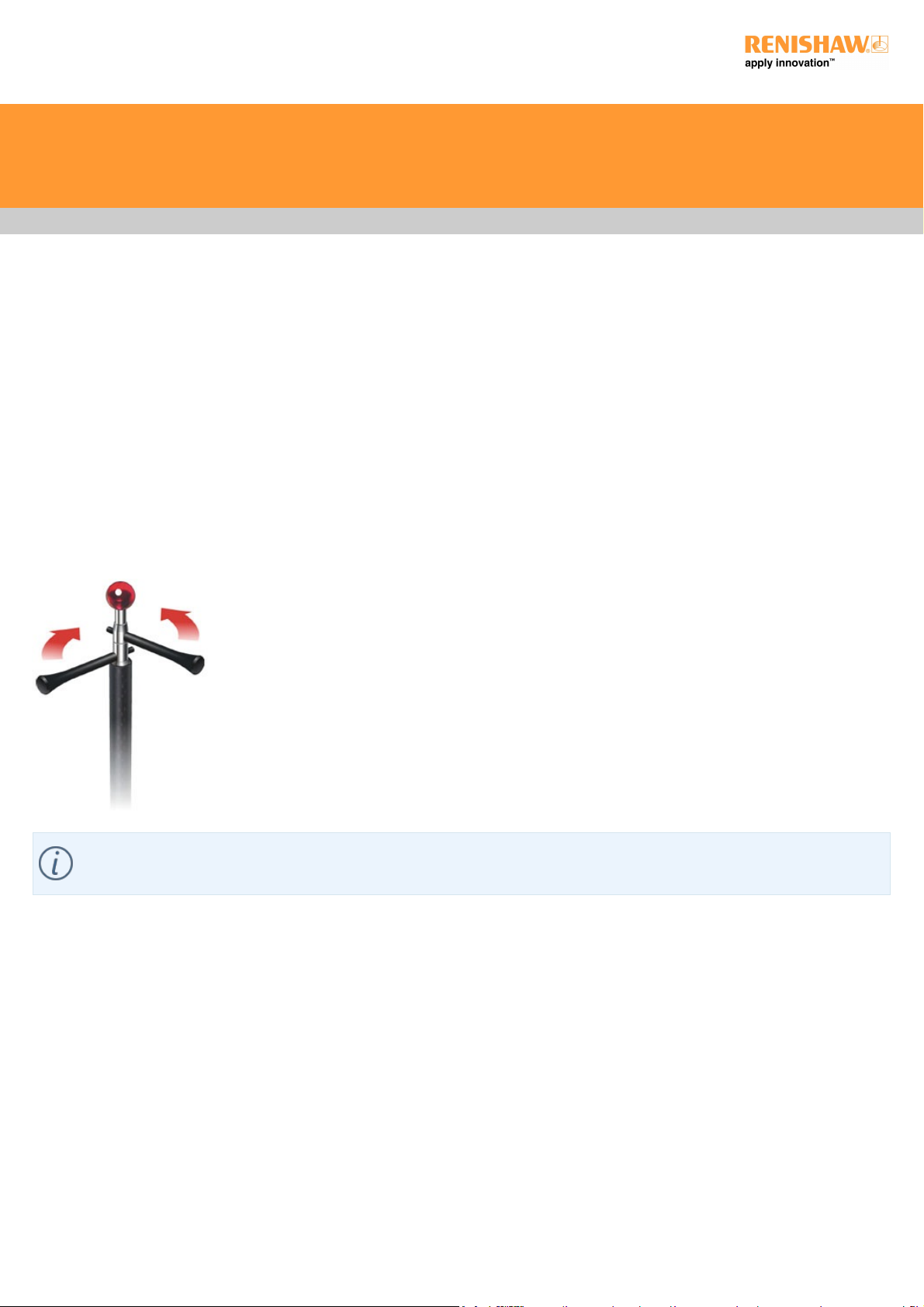
System calibration
It is absolutely crucial that the probe is precisely calibrated for each measurement procedure before measurement is taken. Renishaw
recommends using a universal calibration tower (Renishaw part number A-3060-4590) to ensure best metrology performance with the RSP3
range of scanning probes.
The position of the individual ball styli and their diameters should be established using the probe calibration programme recommended by
the machine manufacturer (see the manufacturer's manual). Each RSP3 probe configuration should initially be calibrated and A0, B0 before
the probe can be calibrated in the required head orientations.
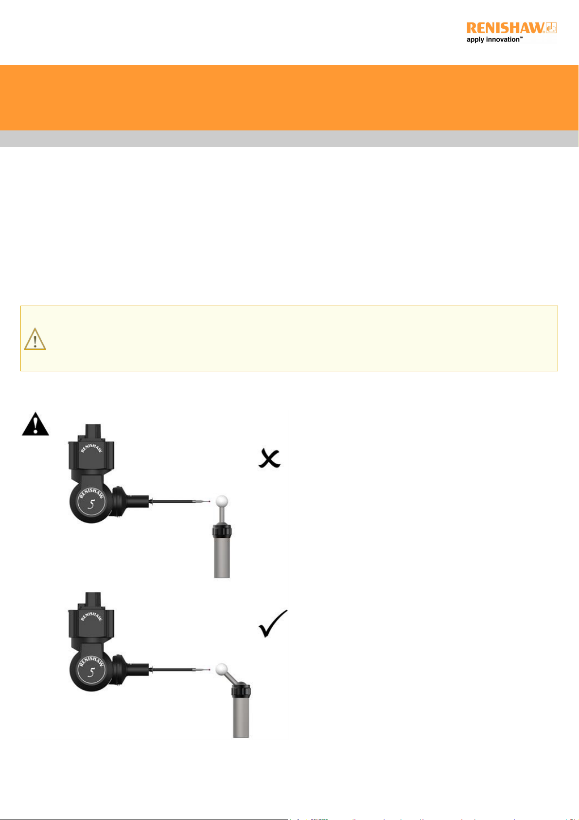
WARNING: It is important, when calibrating the RSP3 probe, that the probe is able to access the full circumference of the
calibration sphere perpendicular to the direction of the stylus. Sub optimal performance is achieved when a probe is unable to scan
the full circumference of the calibration sphere. For instance, to calibrate a probe at both A0, B0 and A90, B0, the calibration sphere
should be mounted with a stalk at 45° to the bed of the CMM.
Calibration with standard gimball datum sphere
RSP3 installation and user's guide
www.renishaw.com
Issued 10 2019
29
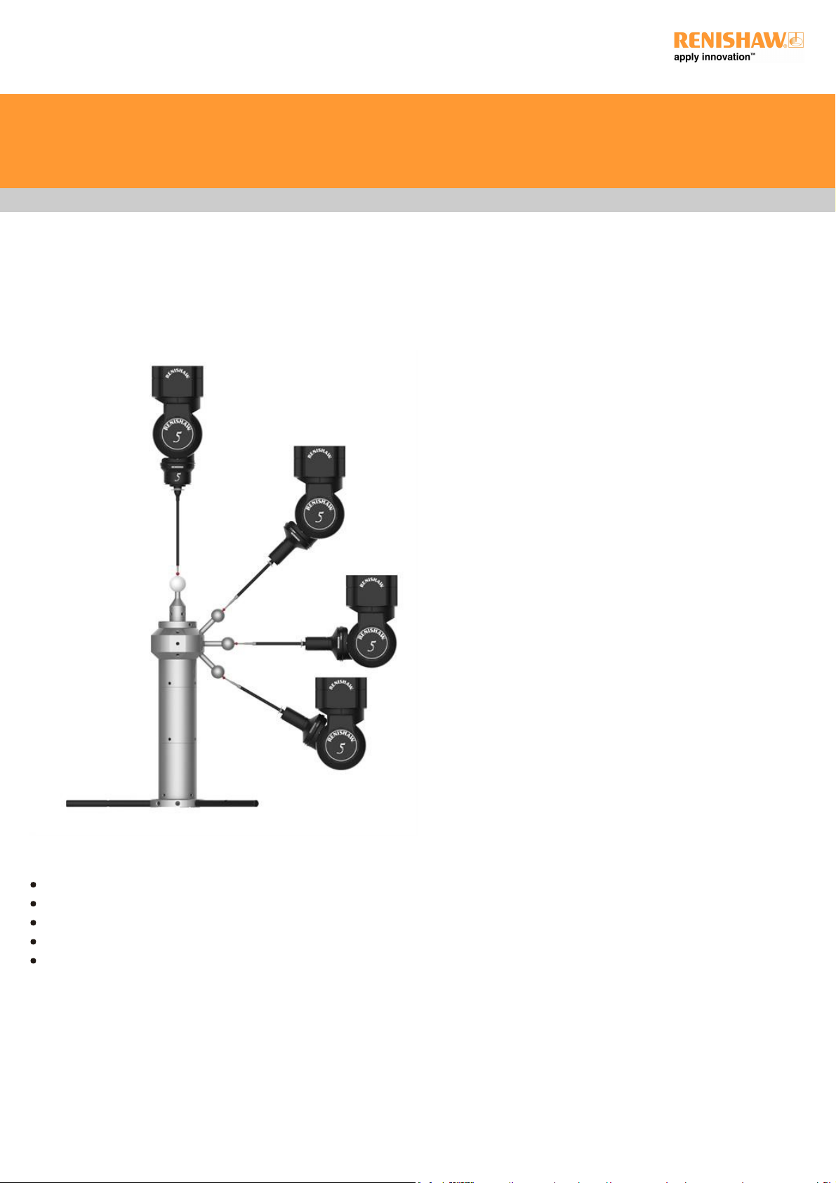
Calibration with universal calibration tower
The universal calibration tower enables calibration of RSP2 and RSP3 probes on a common artefact. The tower is compatible with the REVO
Ø45 mm datum ball for RSP2 calibration, and up to four standard Ø25 mm datum balls for RSP3 calibration. Twelve separate mounting
positions are available, three at each compass point, that allow datum balls to be attached at either +45°, 0° or ‐45°.
Periodic requalification should be performed under the following circumstances:
CMM supplier's recommendations, particularly in respect to temperature changes
At the start of the working day or a shift
After accidental collision
When new probe / stylus configurations are introduced
If the initial state is unknown or uncertain
RSP3 installation and user's guide
www.renishaw.com
Issued 10 2019
30
 Loading...