

Renishaw RP1, RP2 Installation And User Manual
Installation and user’s guide
H-2000-5006-01-G
RP1/RP2 probes

Disclaimer
Considerable effort has been made to ensure
that the contents of this document are free from
inaccuracies and omissions. However,
Renishaw makes no warranties with respect to
the contents of this document and specifically
disclaims any implied warranties. Renishaw
reserves the right to make changes to this
document and to the product described herein
without obligation to notify any person of such
changes.
Trademarks
All brand names and product names used in
this document are trade names, service marks,
trademarks, or registered trademarks of their
respective owners.
© 2002 Renishaw. All rights reserved.
Renishaw® is a registered trademark of
Renishaw plc.
This document may not be copied or
reproduced in whole or in part, or transferred to
any other media or language, by any means,
without the prior written permission of
Renishaw.
The publication of material within this document
does not imply freedom from the patent rights of
Renishaw plc.
Renishaw part no: H-2000-5006-01-G
Issued: June 2002

1-0
Installation and user’s guide
RP1/RP2 probe
Manuel d’installation et d'utilisation
Palpeur RP1/RP2
RP1/RP2 Messtaster
Guida d’installazione e d’uso
Sonda RP1/RP2
Installations und Benutzerhandbuch
2-0
4-0
3-0
Français
English
Italiano
Deutsch

This product conforms to the following European standards:
BS EN 50081-2, BS EN 50082-2 and BS EN 61010-1. It complies
with the relevant essential health and safety and protection
requirements of the following EC Directives: 73/23/EEC as
amended (LOW VOLTAGE), 89/336/EEC as amended (EMC) and
93/68/EEC (CE Marking).
Important
All relevant safety information, including that incorporated in the
installation instructions, user instructions and maintenance
instructions must be observed.
FCC DECLARATION
FCC Section 15.19
This device complies with Part 15 of the FCC rules.
Operation is subject to the following two conditions:
1. This device may not cause harmfull interference.
2. This device must accept any interference received, including
interference that may cause undesired operation.
FCC Section 15.105
This equipment has been tested and found to comply with the limits
for a Class A digital device, pursuant to Part 15 of the FCC rules.
These limits are designed to provide reasonable protection against
harmful interference when the equipment is operated in a
commercial environment. This equipment generates, uses, and can
radiate radio frequency energy and, if not installed and used in
accordance with the instruction manual, may cause harmful
interference to radio communications. Operation of this equipment
in a residential area is likely to cause harmful interference, in which
case you will be required to correct the interference at your own
expense.
FCC Section 15.21
The user is cautioned that any changes or modifications not
expressly approved by Renishaw plc, or authorised representative
could void the user's authority to operate the equipment.
FCC Section 15.27
The user is also cautioned that any peripheral device installed with
this equipment such as a computer, must be connected with a highquality shielded cable to insure compliance with FCC limits.
THE PROBE SYSTEM
Probe systems are easy to use and should
provide many years effective trouble free
operation.
Instructions given in this user guide will help
you to make the best use of your system.
WARRANTY
Equipment requiring attention under warranty
must be returned to your supplier.
No claims will be considered where Renishaw
equipment has been misused, or repairs or
adjustments have been attempted by
unauthorised persons.
CHANGES TO EQUIPMENT
Renishaw reserves the right to change
specifications without notice.
CNC MACHINE
CNC machine tools must always be operated
by competent persons in accordance with
manufacturers instructions.
CARE OF THE PROBE SYSTEM
Keep components reasonably clean.
INSTALLATION AND USERS GUIDE - ENGLISH

F
Informations à l’attention de l’utilisateur
L’effet de pincement dû au mouvement des pièces mobiles
entre elles ou avec des pièces fixes présente des dangers.
Ne pas tenir la tête du palpeur lorsqu’elle se déplace ou que
le palpeur est changé à la main.
Attention aux mouvements brusques. L’utilisateur doit toujours
rester en dehors de la zone de sécurité des installations
multiples Tête de Palpeur/Rallonge/Palpeur.
Le port de lunettes de protection est recommandé pour toute
application sur machine-outil et MMC.
Les conseils de nettoyage en toute sécurité des produits
Renishaw figurent dans la section MAINTENANCE de votre
documentation.
Aucune pièce des machines Renishaw alimentées sur secteur
ne peut être réparée par l’utilisateur. Renvoyer toute machine
défectueuse à un Centre Après Vente Renishaw agréé.
Mettre la machine hors tension avant d’entreprendre toute
opération de maintenance.
Consulter le mode d’emploi du fournisseur de la machine.
Informations à l’attention du fournisseur de la machine
Il incombe au fournisseur de la machine d’assurer que
l’utilisateur prenne connaissance ceux décrits dans la
documentation du produit Renishaw, et d’assurer que des
protections et verrouillages de sûreté adéquats soient prévus.
Dans certains cas, il est possible que le signal du palpeur
indique à tort l’état que le palpeur est au repos. Ne pas se fier
aux signaux du palpeur qui ne garantissent pas toujours l’arrêt
de la machine.
S-1
GB
Information for the user
Pinch hazards exist between moving parts and between moving
and static parts. Do not hold the probe head during movements,
or during manual probe changes.
Beware of unexpected movement. The user should remain
outside of the full working envelope of probe head/extension/
probe combinations.
In all applications involving the use of machine tools or CMMs,
eye protection is recommended.
For instructions regarding the safe cleaning of Renishaw
products, refer to the MAINTENANCE section of the relevant
product documentation.
There are no user serviceable parts inside Renishaw mains
powered units. Return defective units to an authorised
Renishaw Customer Service Centre.
Remove power before performing any maintenance operations.
Refer to the machine supplier’s operating instructions.
Information for the machine supplier
It is the machine supplier’s responsibility to ensure that the
user is made aware of any hazards involved in operation,
including those mentioned in Renishaw product
documentation, and to ensure that adequate guards and
safety interlocks are provided.
Under certain circumstances the probe signal may falsely
indicate a probe seated condition. Do not rely on probe signals
to stop machine movement.

I
Informazioni per l’utente
Tra le parti in moto o tra le parti in moto e quelle ferme esiste
effettivamente il pericolo di farsi del male pizzicandorsi. Evitare
di afferrare la testina della sonda quando è in moto, oppure quando
si effettuano spostamenti a mano.
Fare attenzione ai movimenti inaspettati. Si raccomanda all’utente
di tenersi al di fuori dell’involucro operativo della testina della
sonda, prolunghe e altre varianti della sonda.
Si raccomanda di indossare occhiali di protezione in applicazioni
che comportano macchine utensili e macchine per misurare a
coordinate.
Per le istruzioni relative alla pulizia dei prodotti Renishaw, fare
riferimento alla sezione MANUTENZIONE (MAINTENANCE) della
documentazione del prodotto.
All’interno degli apparecchi Renishaw ad alimentazione di rete
elettrica, non vi sono componenti adatti a interventi di
manutenzione da parte dell’utente. In caso di guasto, rendere
l’apparecchio a uno dei Centri di Assistenza Renishaw.
Prima di effettuare qualsiasi intervento di manutenzione, isolare
dall’alimentazione di rete.
Consultare le istruzioni d’uso del fabbricante della macchina.
Informazioni per il fabbricante della macchina
Il fornitore della macchina ha la responsabilità di avvertire l’utente
dei pericoli inerenti al funzionamento della stessa, compresi quelli
riportati nelle istruzioni della Renishaw, e di mettere a disposizione
i ripari di sicurezza e gli interruttori di esclusione.
E’ possibile, in certe situazioni, che la sonda emetta erroneamente
un segnale che la sonda è in posizione. Evitare di fare affidamento
sugli impulsi trasmessi dalla sonda per arrestare la macchina.
D
Informationen für den Benutzer
Zwischen beweglichen und zwischen beweglichen und
statischen Teilen besteht eine Einklemmgefahr. Den
Meßtasterkopf nicht anfassen, wenn er sich bewegt oder wenn
ein manueller Meßtasterwechsel durchgeführt wird.
Auf unerwartete Bewegungen achten. Der Anwender sill sich
immer außerhalb des Meßtasterkopf-Arm-Meßtaster-Bereichs
aufhalten.
Bei der Bedienung von Werkzeugmaschinen oder
Koordinatenmeßanlagen ist Augenschutz empfohlen.
Anleitungen über die sichere Reinigung von
Renishaw-Produkten sind in Kapitel WARTUNG
(MAINTENANCE) in der Produktdokumentation enthalten.
Die betriebenen Renishaw-Einheiten enthalten keine Teile, die
vom Anwender gewartet werden können. Im Falle von Mängeln
sind diese Geräte an Ihren Renishaw Kundendienst zu senden.
Bevor Wartungsarbeiten begonnen werden, muß erst die
Stromversorgung getrennt werden.
Beziehen Sie sich auf die Wartungsanleitungen des
Lieferanten.
Informationen für den Maschinenlieferanten
Es obliegt dem Maschinenlieferanten, den Anwender über alle
Gefahren, die sich aus dem Betrieb der Ausrüstung,
einschließlich der, die in der Renishaw Produktdokumentation
erwähnt sind, zu unterrichten und zu versichern, daß
ausreichende Sicherheitsvorrichtungen und Verriegelungen
eingebaut sind.
Unter gewissen Umständen könnte das Meßtastersignal
falscherweise melden, daß der Meßtaster nicht ausgelenkt ist.
Verlassen Sie sich nicht allein auf Sondensignale, um sich
über Maschinenbewegungen zu informieren.
S-2

E
Información para el usuario
Existe el peligro de atraparse los dedos entre las distintas partes
móviles y entre partes móviles e inmoviles. No sujetar la cabeza
de la sonda mientras se mueve, ni durante los cambios manuales
de la sonda.
Tener cuidado con los movimientos inesperados. El usuario debe
quedarse fuera del grupo operativo completo compuesto por la
cabeza de sonda/extensión/sonda o cualquier combinación de
las mismas.
Se recomienda usar protección para los ojos en todas las
aplicaciones que implican el uso de máquinas herramientas y
máquinas de medición de coordenadas.
Para instrucciones sobre seguridad a la hora de limpiar los
productos Renishaw, remitirse a la sección titulada
MANTENIMIENTO (MAINTENANCE) en la documentación sobre
el producto.
Dentro de las unidades Renishaw que se enchufan a la red, no
existen piezas que puedan ser mantenidas por el usuario. Las
unidades defectuosas deben ser devueltas a un Centro de Servicio
al Cliente Renishaw.
Quitar la corriente antes de emprender cualquier operación de
mantenimiento.
Remitirse a las instrucciones de manejo del proveedor de la
máquina.
Información para el proveedor de la máquina
Corresponde al proveedor de la máquina asegurar que el usuario
esté consciente de cualquier peligro que implica el manejo de la
máquina, incluyendo los que se mencionan en la documentación
sobre los productos Renishaw y le corresponde también
asegurarse de proporcionar dispositivos de protección y
dispositivos de bloqueo de seguridad adecuados.
Bajo determinadas circunstancias la señal de la sonda puede
indicar erroneamente que la sonda está asentada. No fiarse de
las señales de la sonda para parar el movimiento de la máquina.
P
Informações para o Utilizador
Figo de constrição entre peças móveis e entre peças móveis e
estáticas. Não segurar a Cabeça da Sonda durante o movimento
ou durante mudanças manuais de Sonda.
Tomar cuidado com movimento inesperado. O utilizador deve
permanecer fora do perímetro da área de trabalho das
combinações Cabeça da Sonda/Extensão/ Sonda.
Em todas as aplicações que envolvam a utilização de
Máquinas-Ferramenta e CMMs, recomenda-se usar protecção
para os olhos.
Para instruções relativas à limpeza segura de produtos
Renishaw, consultar a secção MANUTENÇÃO
(MAINTENANCE) da documentação do produto.
Não há peças que possam ser consertadas pelo utilizador
dentro das unidades Renishaw alimentadas pela rede. Devolver
unidades avariadas a um Centro de Atendimento a Clientes
Renishaw.
Desligar a alimentação antes de efectuar qualquer operação
de manutenção.
Consultar as instruções de funcionamento do fornecedor da
máquina.
Informações para o Fornecedor da Máquina
É responsabilidade do fornecedor da máquina assegurar que
o utilizador e consciencializado de quaisquer perigos envolvidos
na operação, incluindo os mencionados na documentação do
produto Renishaw e assegurar que são fornecidos resguardos
e interbloqueios de segurança adequados.
Em certas circunstâncias, o sinal da sonda pode indicar
falsamente uma condição de sonda assentada. Não confiar em
sinais da sonda para parar o movimento da máquina.
S-3
DK
Oplysninger til brugeren
Der er risiko for at blive klemt mellem bevægelige dele og mellem
bevægelige og statiske dele. Hold ikke sondehovedet under
bevægelse eller under manuelle sondeskift.
Pas på uventede bevægelser. Brugeren bør holde sig uden for
hele sondehovedets/forlængerens/sondens arbejdsområde.
I alle tilfælde, hvor der anvendes værktøjs- og
koordinatmålemaskiner, anbefales det at bære øjenbeskyttelse.
Se afsnittet VEDLIGEHOLDELSE (MAINTENANCE) i
produktdokumentationen for at få instruktioner til sikker rengøring
af Renishaw-produkter.
Der er ingen dele inde i Renishaw-enhederne, som sluttes til
lysnettet, der kan efterses eller repareres af brugeren. Send alle
defekte enheder til Renishaws kundeservicecenter
Afbryd strømforsyningen, før der foretages vedligeholdelse.
Se maskinleverandørens brugervejledning.
Oplysninger til maskinleverandøren
Det er maskinleverandørens ansvar at sikre, at brugeren er
bekendt med eventuelle risici i forbindelse med driften, herunder
de risici, som er nævnt i Renishaws produktdokumentation, og
at sikre, at der er tilstrækkelig afskærmning og
sikkerhedsblokeringer.
Under visse omstændigheder kan sondesignalet ved en fejl
angive, at sonden står stille. Stol ikke på, at sondesignaler stopper
maskinens bevægelse.
S-4
GRGR
GRGR
GR

SW
Information för användaren
Risk för klämning existerar mellan rörliga delar och mellan
rörliga och stillastående delar. Håll ej i sondens huvud under
rörelse eller under manuella sondbyten.
Se upp för plötsliga rörelser. Användaren bör befinna sig utanför
arbetsområdet för sondhuvudet/förlängningen/
sond-kombinationerna.
Ögonskydd rekommenderas för alla tillämpningar som
involverar bruket av maskinverktyg och CMM.
För instruktioner angående säker rengöring av Renishaws
produkter, se avsnittet UNDERHÅLL (MAINTENANCE) i
produktdokumentationen.
Det finns inga delar som användaren kan utföra underhåll på
inuti Renishaws nätströmsdrivna enheter. Returnera defekta
delar till ett auktoriserat Renishaw kundcentra.
Koppla bort strömmen innan underhåll utförs.
Se maskintillverkarens bruksanvisning.
Information för maskinleverantören
Maskinleverantören ansvarar för att användaren informeras om
de risker som drift innebär, inklusive de som nämns i Renishaws
produktdokumentation, samt att tillräckligt goda skydd och
säkerhetsförreglingar tillhandahålls.
Under vissa omständigheter kan sondens signal falskt ange
att en sond är monterad. Lita ej på sondsignaler för att stoppa
maskinens rörelse.
S-5
NL
Informatie voor de Gebruiker
Er is risico op klemmen tussen de bewegende onderdelen
onderling en tussen bewegende en niet-bewegende onderdelen.
De sondekop tijdens beweging of tijdens manuele
sondeveranderingen niet vasthouden.
Oppassen voor onverwachte beweging. De gebruiker dient buiten
het werkende signaalveld van de Sondekop/Extensie/Sonde
combinaties te blijven.
Het dragen van oogbescherming wordt tijdens gebruik van
Machinewerktuigen en CMM’s aanbevolen.
Voor het veilig reinigen van Renishaw produkten wordt verwezen
naar het hoofdstuk ONDERHOUD (MAINTENANCE) in de
produktendocumentatie.
De onderdelen van Renishaw units die op het net worden
aangesloten kunnen niet door de gebruiker onderhouden of
gerepareerd worden. U kunt defecte units naar een erkend
Renishaw Klantenservice Centrum brengen of toezenden.
Voordat u enig onderhoud verricht dient u de stroom uit te
schakelen.
De bedieningsinstructies van de machineleverancier raadplegen.
Informatie voor de Machineleverancier
De leverancier van de machine is ervoor verantwoordelijk dat de
gebruiker op de hoogte wordt gesteld van de risico’s die
verbonden zijn aan bediening, waaronder de risico’s die vermeld
worden in de produktendocumentatie van Renishaw. De
leverancier dient er tevens voor te zorgen dat de gebruiker is
voorzien van voldoende beveiligingen en
veiligheidsgrendelinrichtingen.
Onder bepaalde omstandigheden kan het sondesignaal een
onjuiste sondetoestand aangeven. Vertrouw niet op de
sondesignalen voor het stoppen van de machinebeweging.

FIN
Käyttäjälle tarkoitettuja tietoja
Liikkuvien osien sekä liikkuvien ja staattisten osien välillä on
olemassa puristusvaara. Älä pidä kiinni anturin päästä sen
liikkuessa tai vaihtaessasi anturia käsin.
Varo äkillistä liikettä. Käyttäjän tulee pysytellä täysin anturin pään/
jatkeen/anturin yhdistelmiä suojaavan toimivan kotelon
ulkopuolella.
Kaikkia työstökoneita ja koordinoituja mittauskoneita (CMM)
käytettäessä suositamme silmäsuojuksia.
Renishaw-tuotteiden turvalliset puhdistusohjeet löytyvät
tuoteselosteen HUOLTOA (MAINTENANCE) koskevasta osasta.
Sähköverkkoon kytkettävät Renishaw-tuotteet eivät sisällä
käyttäjän huollettavissa olevia osia. Vialliset osat tulee palauttaa
valtuutetulle Renishaw-asiakaspalvelukeskukselle.
Kytke pois sähköverkosta ennen huoltotoimenpiteitä.
Katso koneen toimittajalle tarkoitettuja käyttöhjeita.
Tietoja koneen toimittajalle
Koneen toimittaja on velvollinen selittämään käyttäjälle
mahdolliset käyttöön liittyvät vaarat, mukaan lukien Renishaw’n
tuoteselosteessa mainitut vaarat. Toimittajan tulee myös
varmistaa, että toimitus sisältää riittävän määrän suojia ja lukkoja.
Tietyissä olosuhteissa anturimerkki saattaa osoittaa virheellisesti,
että kyseessä on anturiin liittyvä ongelma. Älä luota
anturimerkkeihin koneen liikkeen pysäyttämiseksi.
S-6
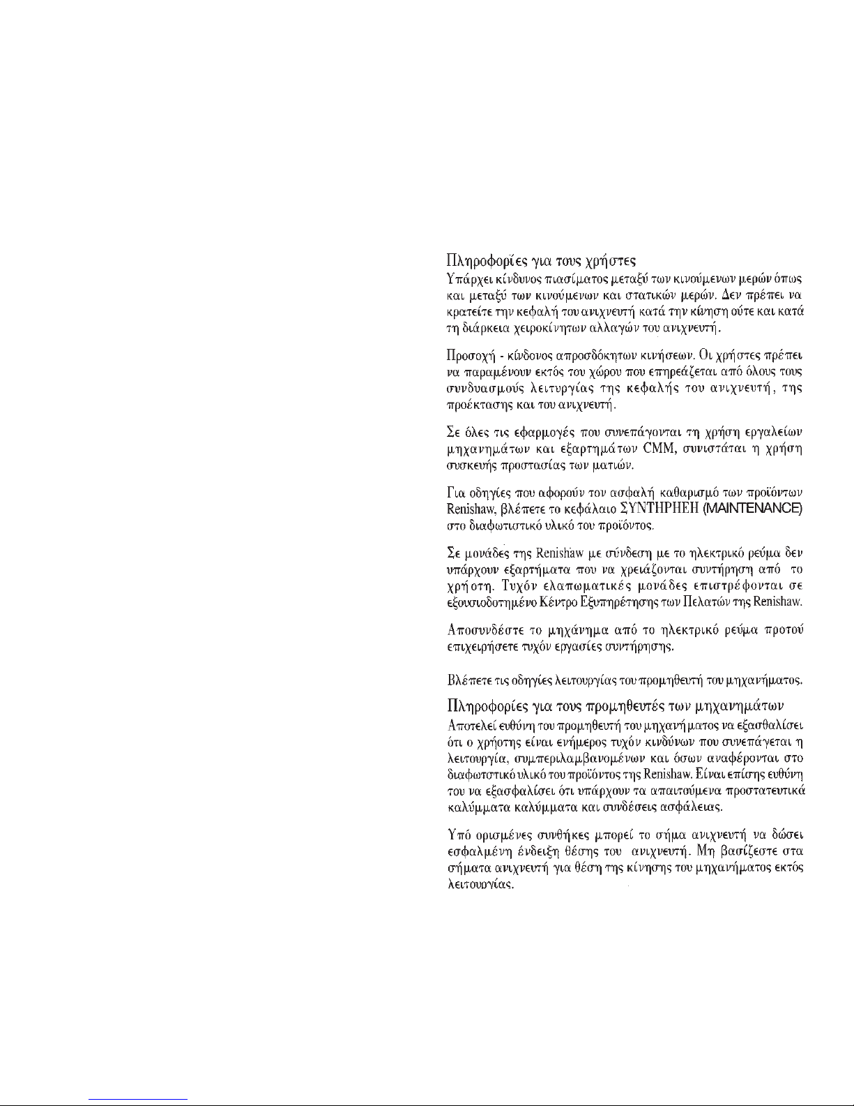
RP1/RP2 PROBE SYSTEM
An inhibit input enables an optical transmission type inspection probe
and interface to be used on the same machine input as the RP1/RP2.
The MI 8 interface unit is fully described in the MI 8 user’s guide, Part No.
H-2000-5015.
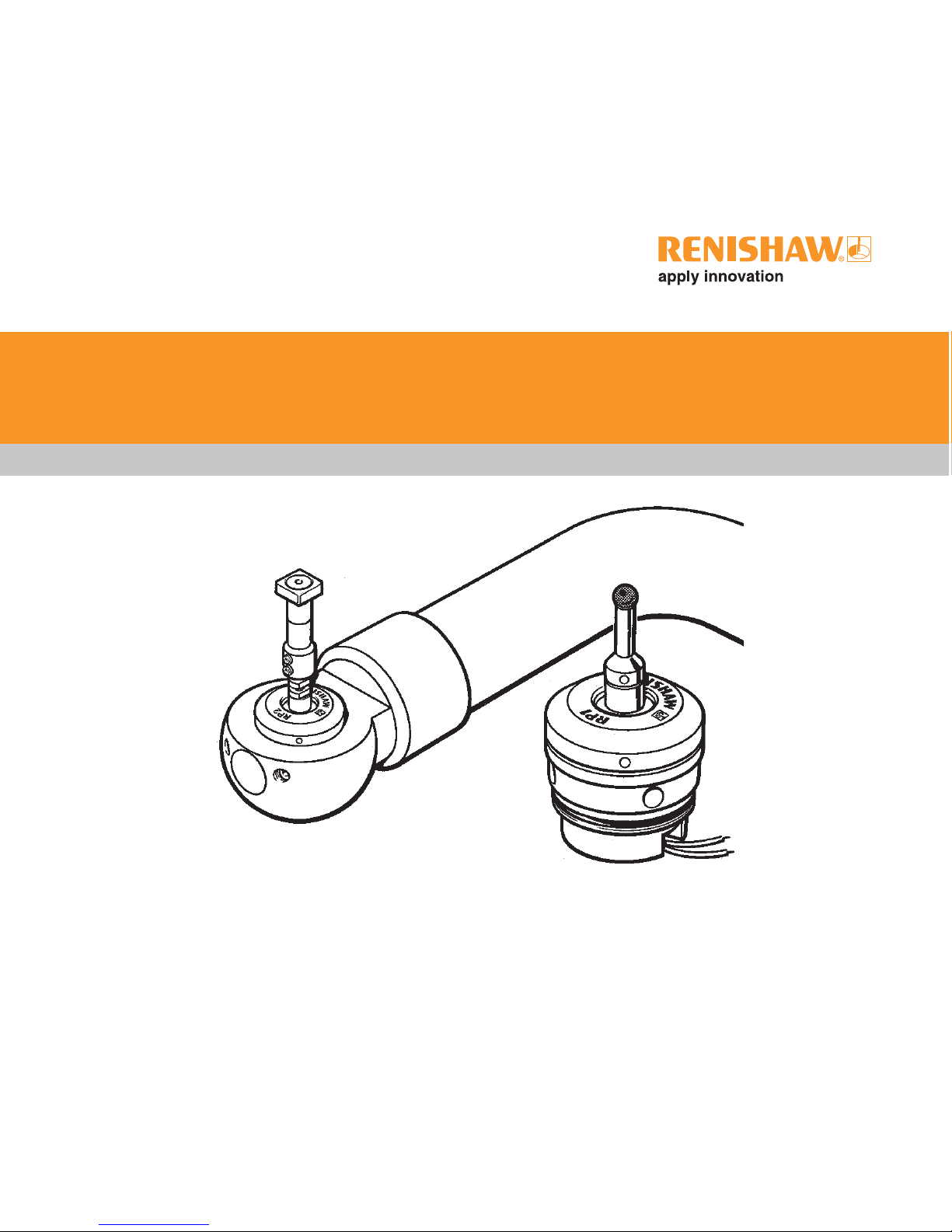
RP1/RP2 PROBE
The Renishaw RP1/RP2 probe is
fitted into a purpose designed
mounting (see installation
diagrams), and is also available
in a double diaphragm version
(RP1 DD/RP2 DD).
The RP2 probe is fitted to the
Renishaw tool setting arm (TSA).
An RP1 or RP2 probe may be
fitted to the Renishaw high
precision arm (HPA).
The RP1/RP1 DD is fitted with
twin wire probe outputs.
The RP2/RP2 DD is fitted with a
connector assembly.
INTERFACE
Signals between the probe and
the CNC control are processed
by an interface unit.
An MI 8 interface unit is
recommended. The MI 8
provides voltage-free solid state
relay (SSR) output, configurable
to be either normally open (NO)
or normally closed (NC).
CNC
machine
control
1-1
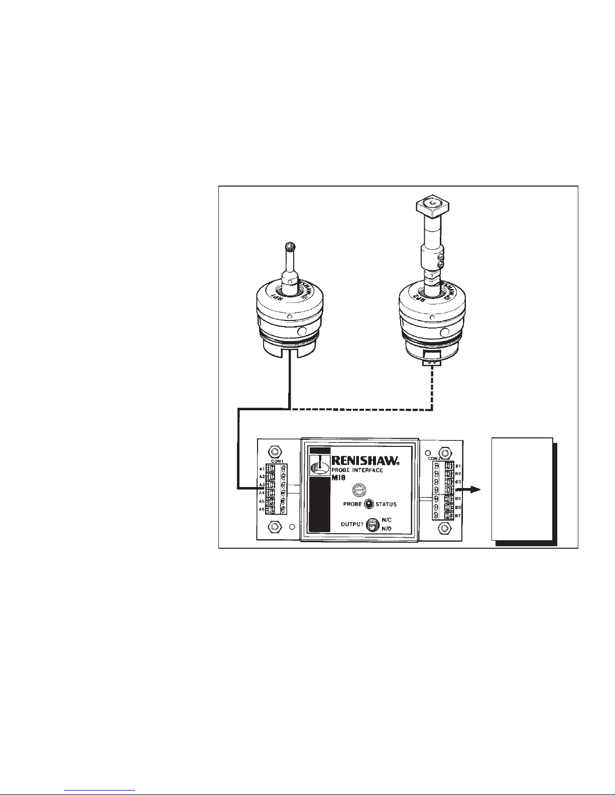
RP1/RP1 DD dimensions mm (in)
1-2
RP1 probe
9,7
(0.38)
Ø30
(1.18)
Ø7
(0.28)
Ø7
(0.28)
RP1 DD probe
11
(0.43)
12.5°
12.5°
16,1
15,0
(0.63
0.59)
5,6 (0.22)
5,4 (0.21)
12.5°
12.5°
16,1 (0.63)
15,0 (0.59)
5,6
5,4
(0.22
0.21)
14,25
(0.56)
7,2
(0.28)
Ø30
(1.18)
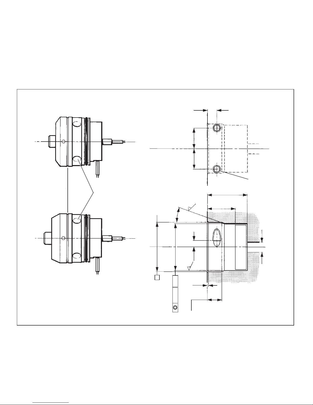
RP1/RP1 DD INSTALLATION dimensions mm (in)
NOTES
1. Side lead exit may be in any position
on diameter marked thus XXXXXXXXX.
2. Ensure face B of module body is
flush within 0.2 mm (0.008 in) of face C
of housing on installation.
3. To secure probe during installation, lock
M5 flat end grubscrews (2 off, supplied by
user) into location c/sinks in probe body.
Side or rear lead
exit customer
configurable.
Wire length
300 mm (2 off)
Side or rear lead
exit customer
configurable.
Wire length
300 mm (2 off)
➛➛
➛➛
➛
FACE B
See Note 2
M4 x 0,7
M4 x 0,7
RP1 DD probe
RP1 probe
Location
c/ sink
Ø6
(0.24)
minimum
lead exit
NOTE It is essential that design of the probe installation prevents coolant from contacting the rear of
the probe.
2 holes M5 x 0,8
to depth shown.
See Note 3
5,6
5,4
(0.22
0.21)
12,6
12,4
(0.49
0.48)
XXXXXXXXXXXXX
23,5 (0.92)
minimum
16,6 (0.65)
minimum
Ø 0,05
A
SECTION D - D
DD
DD
D
20°
DD
DD
D
0,5 x 45°
A
12,6
12,4
(0.49
0.48)
4
(0.16)
8,5
8,3
(0.33
0.32)
FACE C
See Note 2
Ø28,90
Ø28,80
(1.138
1.134)
0,8
1-3
➛➛
➛➛
➛
➤➤
➤➤
➤
➤➤
➤➤
➤
➛➛
➛➛
➛
1-4
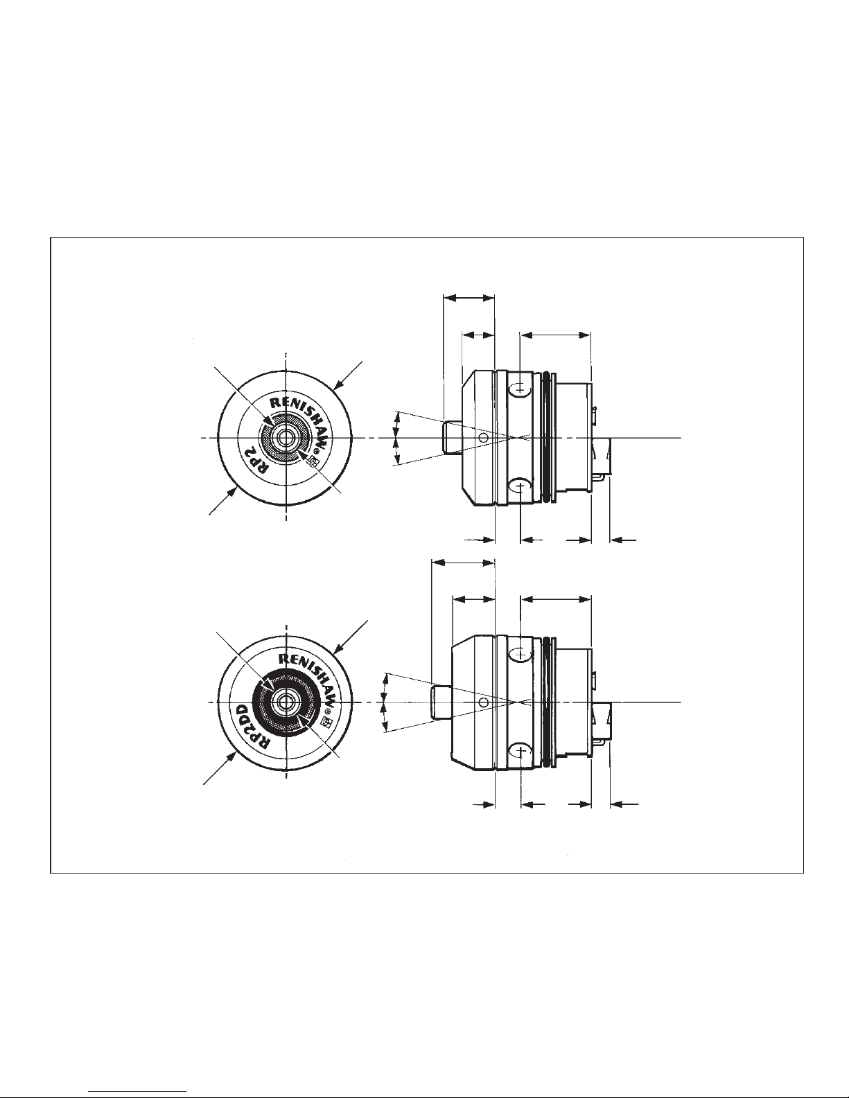
RP2/RP2 DD dimensions mm (in)
Ø30
(1.18)
Ø7
(0.28)
RP2 DD probe
RP2 probe
Ø30
(1.18)
5,6 (0.22)
5,4 (0.21)
9,7
(0.38)
14,25
(0.56)
17,0 (0.67)
15,6 (0.61)
5,6 (0.22)
5,4 (0.21)
3,9
(0.15)
2-way male
connector
3,9
(0.15)
2-way male
connector
12.5°
12.5°
12.5°
12.5°
7,2
(0.28)
17,0 (0.67)
15,6 (0.61)
11
(0.43)
Ø7
(0.28)
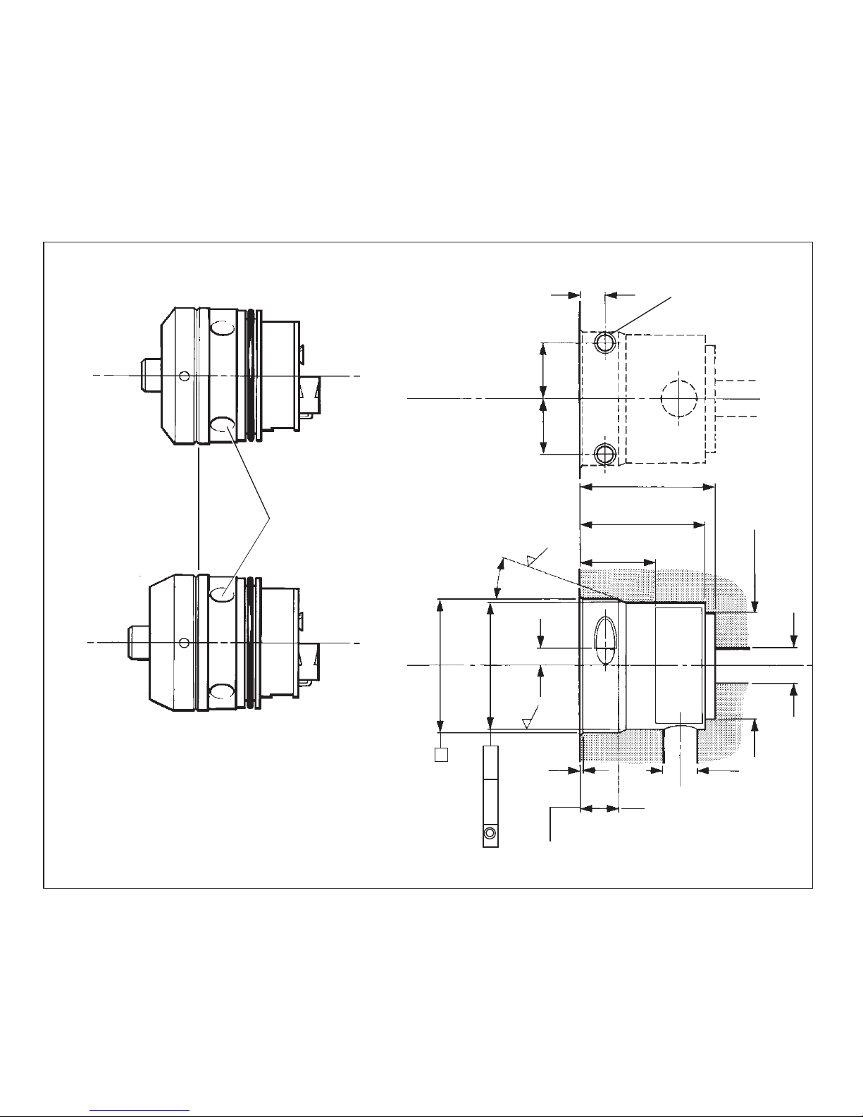
RP2/RP2 DD INSTALLATION dimensions mm (in)
NOTE It is essential that design of the probe installation prevents coolant from contacting the rear of
the probe.
XXXXXXXXXXXXX
16,6 (0.65)
minimum
DD
DD
D
DD
DD
D
FACE B
See Note 2
M4 x 0,7
M4 x 0,7
NOTES
1. Side lead exit may be in any position
on diameter marked thus XXXXXXXXX.
2. Ensure face B of module body is
flush within 0.2 mm (0.008 in) of face C
of housing on installation.
3. To secure probe during installation, lock
M5 flat end grubscrews (2 off, supplied by
user) into location c/sinks in probe body.
SECTION D - D
2 holes M5 x 0,8
to depth shown
See Note 3
5,6
5,4
(0.22
0.21)
12,6
12,4
(0.49
0.48)
12,6
12,4
(0.49
0.48)
30 (1.18)
28 (1.10)
minimum
20°
4
(0.16)
Ø24
(0.94)
Ø28,90
Ø28,80
(1.138
1.134)
Ø30,05
Ø30,00
(1.183
1.181)
FACE C
See Note 2
Ø8
(0.31)
minimum lead exit
0,5 x 45°
A
A
Ø 0,05
8,5
8,3
(0.33
0.32)
RP2 DD probe
RP2 probe
Location
c/sink
0,8
0,8
1-5
➛➛
➛➛
➛
➤➤
➤➤
➤
➤➤
➤➤
➤
➛➛
➛➛
➛
➛➛
➛➛
➛

Primary application
Sense directions
Repeatability (2σ)
Stylus overtravel
Stylus trigger force X Y
Z
Temperature
Operating
Storage
SPECIFICATION
1-6
Tool setting
5-way
1.0 µm (with a 35 mm (1.38 in)
stylus at 480 mm/min)
12.5° in X and Y
4 mm (0.157 in) in Z
125 g (4.4 oz) maximum in high
force direction,
70 g (2.5 oz) minimum in low force
direction
610 g (21.5 oz)
5 °C to 60 °C (41 °F to 140 °F)
-13 °C to +60 °C (9 °F to 140 °F)
RP1/RP2 SPECIFICATION
Connection is made to the RP2 via a 2-way female connector (supplied). This is available as a
Renishaw spare part, or sourced directly from Harwin Connectors.
Female connector Part No.
Renishaw P-CN23-020A
or
Harwin M80-8980205
The following tools are required to assemble the wires
and crimp sockets into the female connector:
Crimp tool Part No.
Used to crimp wire in crimp socket.
Renishaw P-TL04-0005
or
Harwin M22520/2-01
Crimp tool setting : 6
Positioner Part No.
Used to locate crimp socket in crimp tool.
Renishaw P-TL04-0006
or
Harwin T5747
Insertion/removal tool Part No.
Used to insert/remove crimp socket in/from the
connector shell.
Renishaw P-TL04-0007
or
Harwin T5748-19
Wire sizes: 26 (AWG) 19 x 0.1
(Supplied by user) 24 (AWG) 7 x 0.2
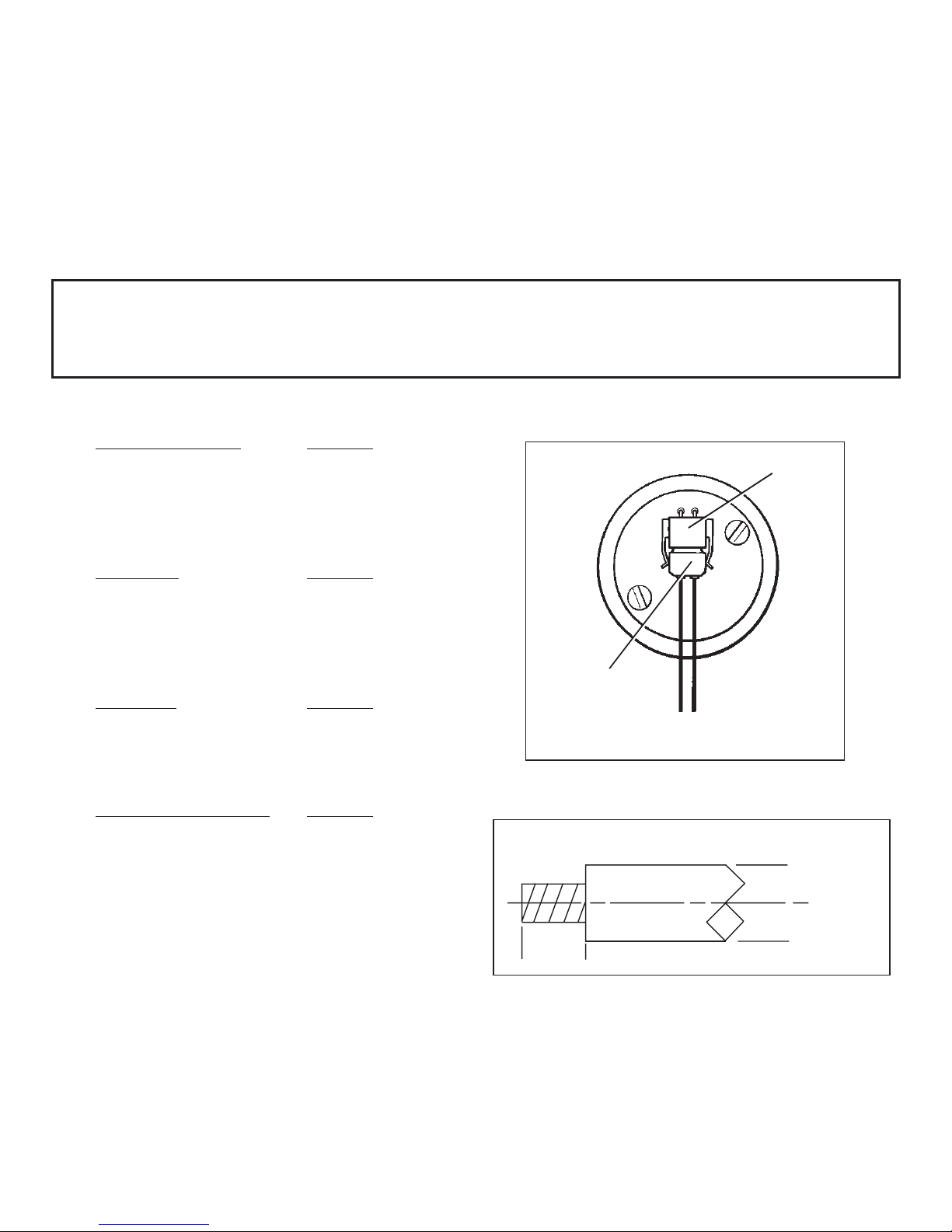
RP2/RP2 DD CONNECTION ASSEMBLY
SAFETY
The RP1/RP2 probe must be installed by a competent person observing relevant safety precautions.
Before commencing work, ensure the machine tool is in a safe condition with the power switched OFF
and the power supply to the MI 8 disconnected.
1-7
2-way
female socket
Rear view of
RP2 probe
Plug
➛➛
➛➛
➛
2.0 mm nominal
Wire stripping
Ø 1.1 mm max.
➛➛
➛➛
➛
➛➛
➛➛
➛
➛➛
➛➛
➛
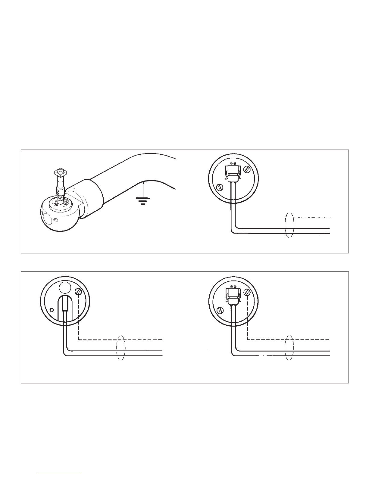
RP1/RP2 ELECTRICAL GROUNDING
ELECTRICAL GROUNDING
Two methods of EMI protection are possible with the RP1/RP2 probe. The method of protection
chosen will depend on the machine wiring with due consideration to ground loops.
1. Grounding via the probe housing (i.e. by the OEM mounting arrangement), where the probe
Housings electrically bonded to the machine earth.
2. Grounding via a cable sheild supplied by the installer, where the probe housing is not electrically
bonded to the machine earth.
Grounding is achieved through the probe mounting screws. Screen should NOT be terminated at the probe.
Grounding is achieved: By terminating the screen at the M2 tapped hole in the rear of the RP1,
or by terminating the screen at the M2 countersunk screw of the RP2.
1-8

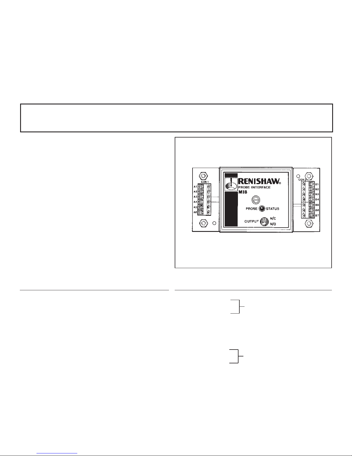
The MI 8 interface unit processes probe signals and converts these signals into a voltage-free solid state relay
(SSR) output, for transmission to the CNC machine control. The MI 8 is fully described in the MI 8 user’s guide,
Part No. H-2000-5015.
Information given here will assist the user when making electrical connections. It is recommended that the
MI 8 is installed within the CNC machine control cabinet. A variant of the MI 8 is also available for DIN rail
mounting.
SPECIFICATION
Supply voltage 15 V to 30 Vdc maximum.
Supply voltage 16.5 V to 28.5 Vdc with 3 V peak-to-peak ripple at 100 Hz.
(with ripple)
Supply current 50 mA nominal.
Supply protection 80 mA (T) anti-surge fuse (F1).
Probe input Normally closed. Open for trigger.
MI 8 output Voltage-free – solid state relay (SSR)
Normally open (N/O) or normally closed (N/C). Selected by switch SW1.
Maximum current 50 mA peak.
Maximum voltage ±50 V peak.
Inhibit input Shorting terminals B1 and B2 (less than 100 Ohms) will force the output into the
seated state, irrespective of actual probe status. Breaking contact between
terminals B1 and B2 (more than 50 k Ohms) will remove the inhibit function.
Remote LED Nominal current of 10 mA. Connection is between terminals B3 and B4.
(Optional) (Locate remote LED in a position where it is easily seen by the machine operator).
Temperature Storage -10 °C to +70 °C (14 °F to 158 °F).
Operating 5 °C to 50 °C (41 °F to 122 °F).
MI 8 INTERFACE UNIT
1-9
PROBE INPUT to MI 8
Pin Description Comments
A1 PROBE INPUT Floating with respect to
0 V
A2 PROBE INPUT Floating with respect to
0 V
A3 SUPPLY SCREEN Connect to cable screen
A4 SUPPLY SCREEN Connect to machine
earth
A5 SUPPLY +ve Positive +15 to 30 Vdc
A6 SUPPLY 0V 0 V
MI 8 OUTPUT to CNC CONTROL
Pin Description Comments
B1 INHIBIT
B2 INHIBIT 0V
B3 EXTERNAL LED +ve
B4 EXTERNAL LED -ve
B5 SCREEN For cable screens
B6 OUTPUT
B7 OUTPUT
SAFETY
Before commencing the installation, ensure the machine tool is in a safe condition
with the power switched OFF.
Inhibit function (active low)
SSR voltage-free
INSTALLATION
When installing an MI 8 interface unit, normal
electronic equipment rules apply (i.e. locate the
MI 8 away from potential sources of interference,
such as three-phase transformers and motor
controllers).
WIRING - PROBE TO MI 8
Use two-core screened cable.
For RP1: Each core Ø2,5 mm (Ø0.10 in) max.
Maximum permitted length 30 m (98 ft).
For RP2: Core range 26 (AWG) 19 x 0.1
24 (AWG) 7 x 0.2
Wire insulation Ø1,1 mm (Ø0.04 in) max.
Maximum permitted length 30 m (98 ft).
MI 8 INTERFACE UNIT
1-10
 Loading...