


Installation guide
H-5480-8504-01-A
RMP40 - radio machine probe

© 2010 Renishaw plc. All rights reserved.
This document may not be copied or reproduced in whole or in part, or transferred to any other media
or language, by any means, without the prior written permission of Renishaw plc.
The publication of material within this document does not imply freedom from the patent rights of
Renishaw plc.
Renishaw part no: H-5480-8504-01-A
First issued: 01.10

Contents
Contents
Before you begin
Before you begin ............................................................1.1
i
Disclaimer
Trademarks
Warranty
Changes to equipment
CNC machines
Care of the probe
Patents
EC Declaration of Conformity
WEEE DIRECTIVE
FCC DECLARATION (USA)
Radio approval
Safety
. . . . . . . . . . . . . . . . . . . . . . . . . . . . . . . . . . . . . . . . . . . . . . . . . . . . . . . . . . . . . . . . . . . . 1.5
..............................................................1.1
.............................................................1.1
................................................................1.1
.....................................................1.1
...........................................................1.1
.........................................................1.1
.................................................................1.2
..................................................1.3
. . . . . . . . . . . . . . . . . . . . . . . . . . . . . . . . . . . . . . . . . . . . . . . . . . . . . . . . . . 1.3
. . . . . . . . . . . . . . . . . . . . . . . . . . . . . . . . . . . . . . . . . . . . . . . . . . . 1.3
.............................................................1.4
RMP40 basics
Introduction . . . . . . . . . . . . . . . . . . . . . . . . . . . . . . . . . . . . . . . . . . . . . . . . . . . . . . . . . . . . . . . . 2.1
Getting started
System interface
. . . . . . . . . . . . . . . . . . . . . . . . . . . . . . . . . . . . . . . . . . . . . . . . . . . . . . . . . . . 2.1
..........................................................2.1
Trigger Logic™
Modes of operation
Configurable settings
Switch on/switch off methods
Enhanced trigger filter
Multiple probe mode
Acquisition mode
RMP40 dimensions
RMP40 specification
...........................................................2.2
. . . . . . . . . . . . . . . . . . . . . . . . . . . . . . . . . . . . . . . . . . . . . . . . . . . . . . . . . . 2.2
.........................................................2.2
.......................................................2.4
. . . . . . . . . . . . . . . . . . . . . . . . . . . . . . . . . . . . . . . . . . . . . . . . . . . . . . . . . 2.4
..........................................................2.5
. . . . . . . . . . . . . . . . . . . . . . . . . . . . . . . . . . . . . . . . . . . . . . . . . . . . . . . . . 2.6
................................................2.2
.....................................................2.2

RMP40 installation guide
System installation
Installing the RMP40 with an RMI ...............................................3.1
Contents
ii
Operating envelope
Performance envelope when using the RMP40 with the RMI
RMP40 / RMI positioning
Performance envelope
Preparing the RMP40 for use
Fitting the stylus
Installing the batteries
Mounting the probe on a shank
Stylus on-centre adjustment
Calibrating the RMP40
Why calibrate a probe?
Calibrating in a bored hole or on a turned diameter
Calibrating in a ring gauge or on a datum sphere
Calibrating the probe length
.......................................................3.1
.......................3.2
...................................................3.2
.....................................................3.2
. . . . . . . . . . . . . . . . . . . . . . . . . . . . . . . . . . . . . . . . . . . . . . . . . . 3.3
..........................................................3.3
.....................................................3.4
. . . . . . . . . . . . . . . . . . . . . . . . . . . . . . . . . . . . . . . . . . . . . . 3.5
.................................................3.6
. . . . . . . . . . . . . . . . . . . . . . . . . . . . . . . . . . . . . . . . . . . . . . . . . . . . . . . 3.7
....................................................3.7
...............................3.7
................................3.7
.................................................3.7
Trigger Logic™
Reviewing the current probe settings . . . . . . . . . . . . . . . . . . . . . . . . . . . . . . . . . . . . . . . . . . . . 4.1
Multiple probe settings
Probe settings record
Changing the probe settings
RMP40 – RMI partnership
Operating mode
.............................................................4.7
.......................................................4.2
. . . . . . . . . . . . . . . . . . . . . . . . . . . . . . . . . . . . . . . . . . . . . . . . . . . . . . . . 4.3
...................................................4.4
.....................................................4.6
Maintenance
Maintenance . . . . . . . . . . . . . . . . . . . . . . . . . . . . . . . . . . . . . . . . . . . . . . . . . . . . . . . . . . . . . . . 5.1
Cleaning the probe
Changing the batteries
Battery type
................................................................5.3
. . . . . . . . . . . . . . . . . . . . . . . . . . . . . . . . . . . . . . . . . . . . . . . . . . . . . . . . . . 5.1
. . . . . . . . . . . . . . . . . . . . . . . . . . . . . . . . . . . . . . . . . . . . . . . . . . . . . . . 5.2
RMP40M system
RMP40M system ............................................................6.1
RMP40M dimensions
RMP40M screw torque values. . . . . . . . . . . . . . . . . . . . . . . . . . . . . . . . . . . . . . . . . . . . . . . . . . 6.2
. . . . . . . . . . . . . . . . . . . . . . . . . . . . . . . . . . . . . . . . . . . . . . . . . . . . . . . . 6.2
Fault finding
Parts list

Before you begin
1.1
Before you begin
Disclaimer
RENISHAW HAS MADE CONSIDERABLE
EFFORTS TO ENSURE THE CONTENT OF THIS
DOCUMENT IS CORRECT AT THE DATE OF
PUBLICATION BUT MAKES NO WARRANTIES
OR REPRESENTATIONS REGARDING
THE CONTENT. RENISHAW EXCLUDES
LIABILITY, HOWSOEVER ARISING, FOR ANY
INACCURACIES IN THIS DOCUMENT.
Trademarks
RENISHAW® and the probe emblem used in the
RENISHAW logo are registered trademarks of
Renishaw plc in the UK and other countries.
apply innovation™ and Trigger Logic™ are
trademarks of Renishaw plc.
Changes to equipment
Renishaw reserves the right to change equipment
specifications without notice.
CNC machines
CNC machine tools must always be operated by
fully trained personnel in accordance with the
manufacturer's instructions.
Care of the probe
Keep system components clean and treat the
probe as a precision tool.
All other brand names and product names used
in this document are trade names, service marks,
trademarks, or registered trademarks of their
respective owners.
Warranty
Equipment requiring attention under warranty
must be returned to your equipment supplier.
No claims will be considered where Renishaw
equipment has been misused, or where
repairs or adjustments have been attempted by
unauthorised persons. Prior consent must be
obtained in instances where Renishaw equipment
is to be substituted or omitted. Failure to comply
with this requirement will invalidate the warranty.

RMP40 installation guide
1.2
Before you begin
Patents
Features of the RMP40 probe, and other similar
Renishaw probes, are subject of one or more of
the following patents and/or patent applications:
CN 100466003
CN 101287958
CN 101482402
EP 0652413
EP 0695926
EP 1185838
EP 1373995
EP 1425550
EP 1457786
EP 1477767
EP 1477768
EP 1576560
EP 1701234
EP 1734426
EP 1804020
EP 1931936
EP 1988439
IN 2004-057552
IN 2004-057552
IN 2007-028964
IN 215787
JP 2004-279417
JP 2008-203270
JP 3126797
JP 3967592
JP 2004-522961
JP 2006-313567
JP 2006-511860
JP 2009-507240
JP 4237051
TW 200720626
US. 5150529
US. 5279042
US. 5669151
US. 7285935
US. 6776344
US. 2006-0215614
US. 2009-0049704
US. 2009-0130987
US. 6776344
US. 6941671
US. 7145468
US. 7441707
US. 7486195

1.3
Before you begin
C
Renishaw PLC hereby declares that the RMP40 is
in compliance with the essential requirements and
other relevant provisions of Directive 1999/5/EC.
Contact Renishaw PLC at
www.renishaw.com/rmp40/cert
for the full EC Declaration of Conformity.
WEEE DIRECTIVE
The use of this symbol on Renishaw products
and/or accompanying documentation indicates
that the product should not be mixed with
general household waste upon disposal. It is the
responsibility of the end user to dispose of this
product at a designated collection point for waste
electrical and electronic equipment (WEEE) to
enable reuse or recycling. Correct disposal of
this product will help to save valuable resources
and prevent potential negative effects on the
environment. For more information, please contact
your local waste disposal service or Renishaw
distributor.
FCC DECLARATION (USA)
FCC Section 15.19
This device complies with Part 15 of the FCC
rules.
Operation is subject to the following two
conditions:
1. This device may not cause harmful
interference.
2. This device may accept any interference
received, including interference that may
cause undesired operation.
FCC Section 15.105
This equipment has been tested and found to
comply with the limits for a Class A digital device,
pursuant to Part 15 of the FCC rules. These limits
are designed to provide reasonable protection
against harmful interference when the equipment
is operated in a commercial environment. This
equipment generates, uses, and can radiate
radio frequency energy and, if not installed
and used in accordance with the instruction
manual, may cause harmful interference to radio
communications. Operation of this equipment
in a residential area is likely to cause harmful
interference, in which case you will be required to
correct the interference at your own expense.
FCC Section 15.21
The user is cautioned that any changes or
modifications not expressly approved by
Renishaw plc, or authorised representative could
void the user’s authority to operate the equipment.

RMP40 installation guide
1.4
Before you begin
Radio approval
PENDING RADIO APPROVAL

1.5
Before you begin
Safety
!
Information to the user
The RMP40 and RMP40M are supplied with two
non-rechargeable ½ AA lithium metal batteries.
Once the charge in these batteries is depleted,
please dispose of them in accordance with your
local environmental and safety laws. Do not
attempt to re-charge these batteries.
Please ensure replacement batteries are of the
correct type and are fitted with the correct polarity
in accordance with the instructions in this manual
and as indicated on the product. For specific
battery operating, safety and disposal guidelines,
please refer to the battery manufacturers'
literature.
• Ensurethatallbatteriesareinsertedwith
the correct polarity.
• Donotstoreindirectsunlightorrain.
Information to the machine supplier/ installer
It is the machine supplier's responsibility to ensure
that the user is made aware of any hazards
involved in operation, including those mentioned
in Renishaw product literature, and to ensure
that adequate guards and safety interlocks are
provided.
Under certain circumstances, the probe signal
may falsely indicate a probe seated condition. Do
not rely on probe signals to halt the movement of
the machine.
Information to the equipment installer
All Renishaw equipment is designed to comply
with the relevant EEC and FCC regulatory
requirements. It is the responsibility of the
equipment installer to ensure that the following
guidelines are adhered to, in order for the product
to function in accordance with these regulations:
• Donotheatordisposeofthebatteryinfire.
• Avoidforceddischargeofthebattery.
• Donotshortcircuit.
• Donotdisassemble,applyexcessive
pressure, pierce or deform.
• Donotswallowandkeepoutofreachof
children.
• Donotgetbatterywet.
If battery is damaged, exercise caution when
handling.
Please ensure that you comply with international
and national battery transport regulations when
transporting batteries or the products. Lithium
batteries are classified as dangerous goods and
strict controls apply on their shipment by air. To
reduce the risk of shipment delays, should you
need to return the products to Renishaw for any
reason, do not return any batteries.
The RMP40 has a glass window. Handle with care
if broken to avoid injury.
any interface MUST be installed in a position
•
away from any potential sources of electrical
noise, i.e. power transformers, servo drives
etc;
all ground connections should be connected
•
to the machine 'star point' (the 'star point'
is a single point return for all equipment
ground and screen cables). This is very
important and failure to adhere to this
can cause a potential difference between
grounds;
all screens must be connected as outlined in
•
the user instructions;
cables must not be routed alongside high
•
current sources, i.e. motor power supply
cables etc, or be near high speed data lines;
cable lengths should always be kept to a
•
minimum.
Equipment operation
If this equipment is used in a manner not specified
by the manufacturer, the protection provided by
the equipment may be impaired.

Before you begin
1.6
RMP40 installation guide
This page left intentionally blank

RMP40 basics
2.12.1
Introduction
RMP40 forms part of Renishaw's family of new
generation radio transmission probes. It is ideally
suited to large machine centres or where line-ofsight between probe and receiver is difficult to
achieve or where Z travel is limited.
RMP40 features an integrated probe module
delivering exceptional robustness and generous
overtravel.
RMP40 complies with FCC regulations and
operates in the 2.4 GHz band. It delivers
interference-free transmission through the use of
FHSS (Frequency Hopping Spread Spectrum).
This allows many systems to operate in the same
machine shop without risk of cross-interference.
All RMP40 settings are configured using ‘Trigger
Logic’. This technique enables the user to review
and subsequently change probe settings by
deflecting the stylus whilst observing the LED
display.
Configurable settings are:
Getting started
Three multicolour LEDs provide visual indication
of selected probe settings.
For example:
Switch-on and switch-off methods
•
• Probe status - triggered or seated
• Battery condition
Batteries are inserted or removed as shown (see
‘RMP40 batteries’ for further information).
On insertion of batteries, the LEDs will begin to
flash (see ‘Reviewing current probe settings’ for
further information).
System interface
The RMI integrated interface/receiver is used to
communicate between the RMP40 probe and the
machine controller.
• Radio on / Radio off
• Radio on / Timer off
• Spin on / Spin off
• Spin on / Timer off
• Filter on / Filter off
• Multiple probe mode on / multiple probe
mode off.

RMP40 installation guide
2.2
RMP40 basics
Trigger Logic™
Trigger Logic™ (see Section 4, "Trigger Logic™")
is a method that allows the user to view and select
all available mode settings in order to customise a
probe to suit a specific application. Trigger Logic™
is activated by battery insertion and subsequent
stylus deflection. A sequence of stylus deflection
(triggering) is then used to systematically lead
the user through the available choices to allow
selection of the required mode options.
Current probe settings can be reviewed by
simply removing the batteries for a minimum of
5 seconds, and then replacing them to activate
the Trigger Logic™ review sequence.
Modes of operation
The RMP40 probe can be in one of three modes:
Configurable settings
Switch on/switch off methods
The following switch on/switch off options are
user-configurable.
1. Radio on / Radio off
2. Radio on / Timer off
3. Spin on / Spin off
4. Spin on / Timer off
Enhanced trigger filter
Probes subjected to high levels of vibration or
shock loads may output signals without having
contacted any surface. The enhanced trigger filter
improves the probes resistance to these effects.
Standby mode: where the probe is awaiting a
switch on signal.
Operational mode: activated by one of the switch
on methods described on this page. In this mode
the RMP40 is ready for use.
Configuration mode: where Trigger Logic™ may
be used to configure the following probe settings.
When the filter is enabled, a constant 10 ms delay
is introduced to the probe output.
The RMP40 is factory set to trigger filter off.
NOTE:
approach speed to allow for the increased stylus
overtravel during the extended time delay.
It may be necessary to reduce the probe

2.3
RMP40 basics
RMP40 switch on method
Switch on options are configurable
RMP40 switch off method
Switch off options are configurable
Switch on time
Radio on
Radio switch on is commanded by
machine input.
Spin on
Spin at 500 rev/min for 1 second
minimum (6 seconds maximum).
Radio off
Radio switch off is commanded by
machine input. A timer automatically
switches the probe off 90 minutes
after the last trigger if it is not turned
off by machine input.
Timer off (timeout)
Timeout will occur 12, 33 or 134
seconds (user configurable) after the
last probe trigger or reseat.
Spin off
Spin at 500 rev/min for 1 second
minimum (6 seconds maximum).
A timer automatically switches the
probe off 90 minutes after the last
trigger if it is not spun.
1 second maximum
Note: This assumes
a good radio
communication link.
In a poor RF
environment this may
rise to a maximum of
3 seconds.
2 seconds maximum.
Note: The 2 seconds
starts from the
moment the spindle
reaches 500 rev/min.
Timer off (timeout)
Timeout will occur 12, 33 or 134
seconds (user configurable) after the
last probe trigger or reseat.
NOTE: After being switched on, the RMP40 must be on for 1 second minimum (the RMP40 must be
spun down before it can be spun off again) before being switched off.

RMP40 installation guide
2.4
RMP40 basics
Multiple probe mode
The RMP40 can be configured, using Trigger
Logic™, to allow multiple radio probes to be used
with a single RMI.
NOTES:
The 'radio on' switch on method cannot be used
in multiple probe mode. Multiple probe mode will
not appear as an option if the 'radio on' option has
been selected.
RMP40 probes which are set to 'multiple probe
mode on' can coexist alongside any number of
RMP40 probes set to 'mode off'.
To allow multiple radio probes to work in close
proximity, and with a single RMI, 16 choices of
'mode on' colours are available, each representing
a different machine tool installation. The colour
choices available are as shown on page 4.2.
All probes operating with a single RMI must be set
to the same 'mode on' colour choice; any multiple
probes located on adjacent machines must all be
set to an alternative 'mode on' colour choice.
Only one probe per 'mode on' colour choice needs
to be partnered with the RMI as, by configuring
multiple probes to a single 'mode on' colour
choice, all probes using this 'mode on' colour
choice will have the same identity. The probe to be
partnered is partnered after selecting the 'multiple
probe mode' setting and choosing the 'mode
on' option. See 'Changing the probe settings' in
Section 4, "Trigger Logic™".
The addition of any further probe(s) into a single
probe installation will require that all probes are
reconfigured to the same 'mode on' colour choice
and that one of the probes is then repartnered
with the RMI.
The addition of any further probe(s), or
replacements, into a multi-probe installation can
be achieved simply through the reconfiguration of
the probe to the same 'mode on' colour choice.
Acquisition mode
System set-up is achieved using Trigger Logic™
and powering on the RMI.
Partnering is only required during initial system
set-up. Further partnering is only required if either
the RMP40 or RMI is changed.
Partnering will not be lost by reconfiguration of
probe settings or when changing batteries, except
where multiple probe mode is selected .
Partnering can take place anywhere within the
operating envelope.
There is no limit to the number of probes that can
be used with a single RMI so long as they all have
the same 'mode on' colour choice.
All RMP40 probes are factory set to 'mode off'.
2.5
RMP40 basics
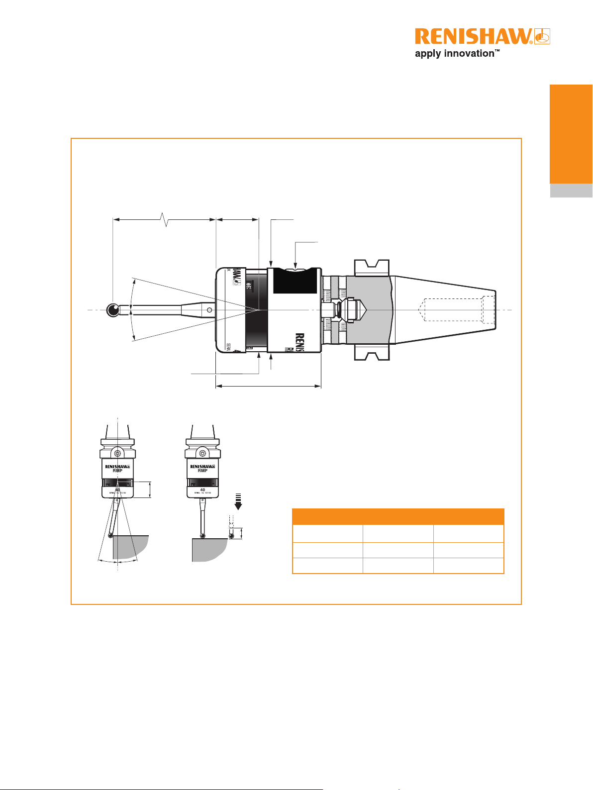
RMP40 dimensions
50 (1.97)
M4 stylus
12.5°
12.5°
Dimensions given in mm (in)
19 (0.75)
Ø40 (Ø1.57)
Battery cassette
RMP40 window
±X ±Y
50 (1.97)
+Z
A range of probe-ready
shanks is available from
Renishaw
Stylus overtravel limits
Stylus length ±X/±Y +Z
50 (1.97) 12 (0.47) 6 (0.24)
100 (3.94) 22 (0.87) 6 (0.24)
 Loading...