

Renishaw RCH25U30J00A, RCH24H30D30A, RGH24U Series, RGH25U Series Installation Manual

Installation guide
M-9541-0084-04-C
RGH24/25U series readhead
EMC compliance
The RG2 encoder system conforms to the relevant harmonised European standards for
electromagnetic compatibility as detailed below.
BS EN 61326
Patents
Features of Renishaw’s encoder systems and similar products are the subjects of the following
patents and patent applications:
EP 0207121 JP 1549396 US 4959542 EP 0274491
US 4,974,962 EP 0274492 US 4926566 EP 0383901
JP 2,963,926 US 5,088,209 EP 0388453 JP 2837483
US 5,063,685 EP 0514081 JP 3,202,316 US 5,241,173
EP 0543513 JP 248,895/1993 US 5,302,820 EP 0748436
US 5,861,953 EP 826138 B JP 506,211/1999 US 6,051,971
EP 1147377 JP 2003-512,611 US 6,588,333 B1
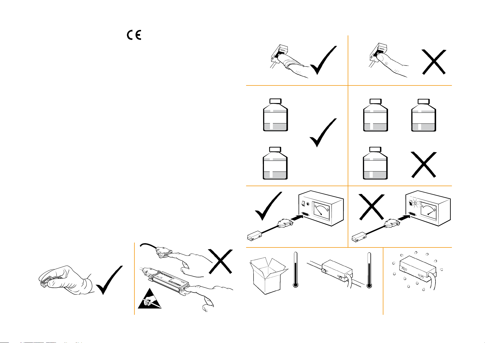
Storage and handling (continued)
N-heptane
CH3(CH2)5CH
3
Acetone
CH3COCH
3
Chlorinated
Solvents
Further information
For further information relating to the installation of RGH24/25 readheads, see also the RGH24
and/or the RGH25 (UHV) Data sheets (Part numbers L-9517-0166, L-9517-0168 and L-9517-9164),
and the Scale installation guide (Part number M-9517-2855). These can be downloaded from our
website www.renishaw.com/encoder and are also available from your local representative.
This document may not be copied or reproduced in whole or in part, or transferred to any other
media or language, by any means without the written prior permission of Renishaw.
The publication of material within this document does not imply freedom from the patent rights of
Renishaw plc.
Disclaimer
Considerable effort has been made to ensure that the contents of this document are free from
inaccuracies and omissions. However, Renishaw makes no warranties with respect to the contents
of this document and specifically disclaims any implied warranties. Renishaw reserves the right to
make changes to this document and to the product described herein without obligation to notify any
person of such changes.
Storage and handling
UHV version only
Propan-2-ol
CH3CHOHCH
3
+70 °C
-20 °C
System
Methylated
Spirits
+55 °C
0 °C
System
Storage <95% RH
Operating <80% RH
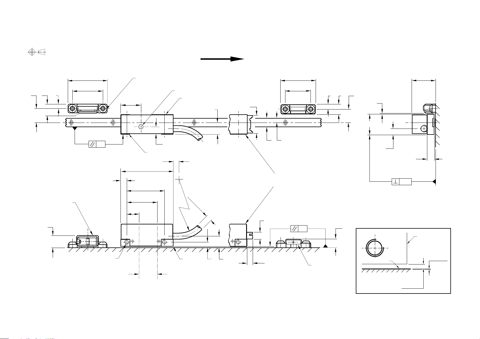
RGH24/ 25 Installation drawing
Dimensions and tolerances in mm.
27
9.5
6.2
A-9541-0037
Reference mark
8.5*
3
actuator
21
0.3
(Yaw Tol. ± 0.5°)
Arrow indicates forward direction of
Fixing screws
M3 x 0.5 x 8
12.8
readhead relative to scale
Set-up LED
Alternative mounting face
8
11.9
23
17
3
6
9.3
0.8
15.8*
13.5
3
5.5
Mounting face
>4
6
3.8
4.8
(Extent of mounting faces)
36
4
26
21.1
>R20 Dynamic bend radius
>R10 Static bend radius
Ø4.4 max
JST connector
version
0.09
(Roll Tol. ± 1°)
8.5
5
(Pitch Tol. ± 1°)
0.6
6.4*
Detail A
Readhead
2 Mounting holes
M3 x 0.5 through
*Dimensions measured from substrate
Optical centreline
A
4*
Reference mark sensor /
limit switch sensor position
Scale
8*
4.3
Scale surface
thickness
0.2
A-9541-0040
Limit switch
actuator
Readhead to
scale clearance
0.8 ± 0.1
Rideheight
 Loading...