

Page 1
Installation guide
M-9531-9818-01-B
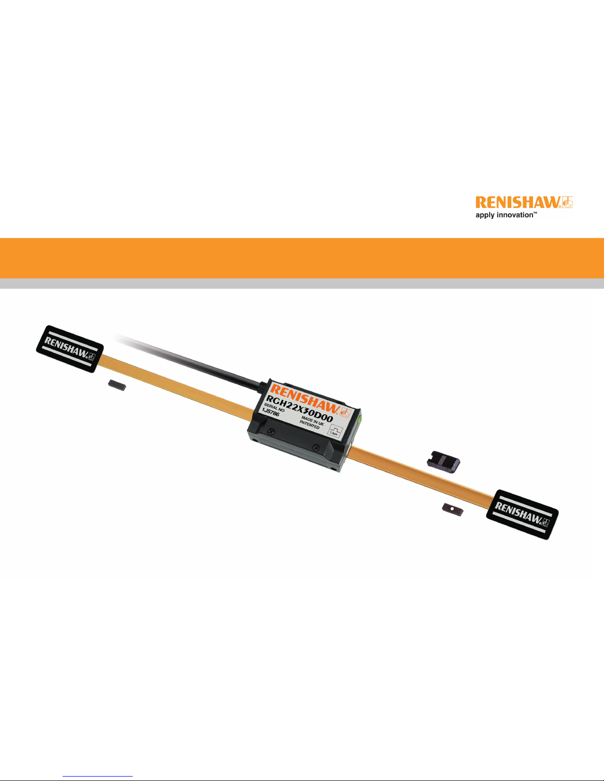
RGH22 RGS20 linear encoder system
Page 2

Contents
Product compliance 1
Storage and handling 2
RGH22 readhead installation drawing 3
RGS20 scale installation drawing 4
Scale application 5
End clamps 5
Reference mark and limit switch actuator installation 6
Readhead mounting and alignment 6
Reference mark set-up 7
Limit switch 7
Output signals 7
Speed 8
Electrical connections 9
Output specications 10
General specications 12
Scale specications 12
RGH22 RGS20 installation guide
Page 3
1
RGH22 RGS20 installation guide
Product compliance
C
Renishaw plc declares that RGH22 complies with the applicable standards and regulations.
A copy of the EC Declaration of Conformity is available on request.
FCC compliance
This device complies with part 15 of the FCC Rules. Operation is subject to the following two conditions:
(1) This device may not cause harmful interference, and (2) this device must accept any interference
received, including interference that may cause undesired operation.
The user is cautioned that any changes or modications not expressly approved by Renishaw plc or
authorised representative could void the user’s authority to operate the equipment.
This equipment has been tested and found to comply with the limits for a Class A digital device,
pursuant to part 15 of the FCC Rules. These limits are designed to provide reasonable protection
against harmful interference when the equipment is operated in a commercial environment.
This equipment generates, uses, and can radiate radio frequency energy and, if not installed
and used in accordance with the instruction manual, may cause harmful interference to radio
communications. Operation of this equipment in a residential area is likely to cause harmful
interference in which case the user will be required to correct the interference at his own expense.
NOTE: This unit was tested with shielded cables on the peripheral devices. Shielded cables must be
used with the unit to ensure compliance.
RoHS compliance
Compliant with EC directive 2011/65/EU (RoHS)
Further information
Further information relating to the RGH22 encoder range can be found in the RGH22 encoder system
Data sheet (L-9517-9676). This can be downloaded from our website www.renishaw.com/encoder
and is also available from your local representative. This document may not be copied or reproduced
in whole or in part, or transferred to any other media or language, by any means without the written
prior permission of Renishaw. The publication of material within this document does not imply freedom
from the patent rights of Renishaw plc.
Disclaimer
RENISHAW HAS MADE CONSIDERABLE EFFORTS TO ENSURE THE CONTENT OF THIS
DOCUMENT IS CORRECT AT THE DATE OF PUBLICATION BUT MAKES NO WARRANTIES
OR REPRESENTATIONS REGARDING THE CONTENT. RENISHAW EXCLUDES LIABILITY,
HOWSOEVER ARISING, FOR ANY INACCURACIES IN THIS DOCUMENT.
The use of this symbol on Renishaw products and/or accompanying documentation indicates that the product
should not be mixed with general household waste upon disposal. It is the responsibility of the end user to
dispose of this product at a designated collection point for waste electrical and electronic equipment (WEEE)
to enable reuse or recycling. Correct disposal of this product will help to save valuable resources and prevent
potential negative effects on the environment. For more information, please contact your local waste disposal
service or Renishaw distributor.
The packaging of our products contains the following materials and can be recycled.
Packaging Component Material ISO 11469 Recycling Guidance
Outer box Cardboard Not applicable Recyclable
Polypropylene PP Recyclable
Inserts Low Density Polyethylene Foam LDPE Recyclable
Cardboard Not applicable Recyclable
Bags High Density Polyethylene Bag HDPE Recyclable
Metalised Polyethylene PE Recyclable
Page 4
2
RGH22 RGS20 installation guide
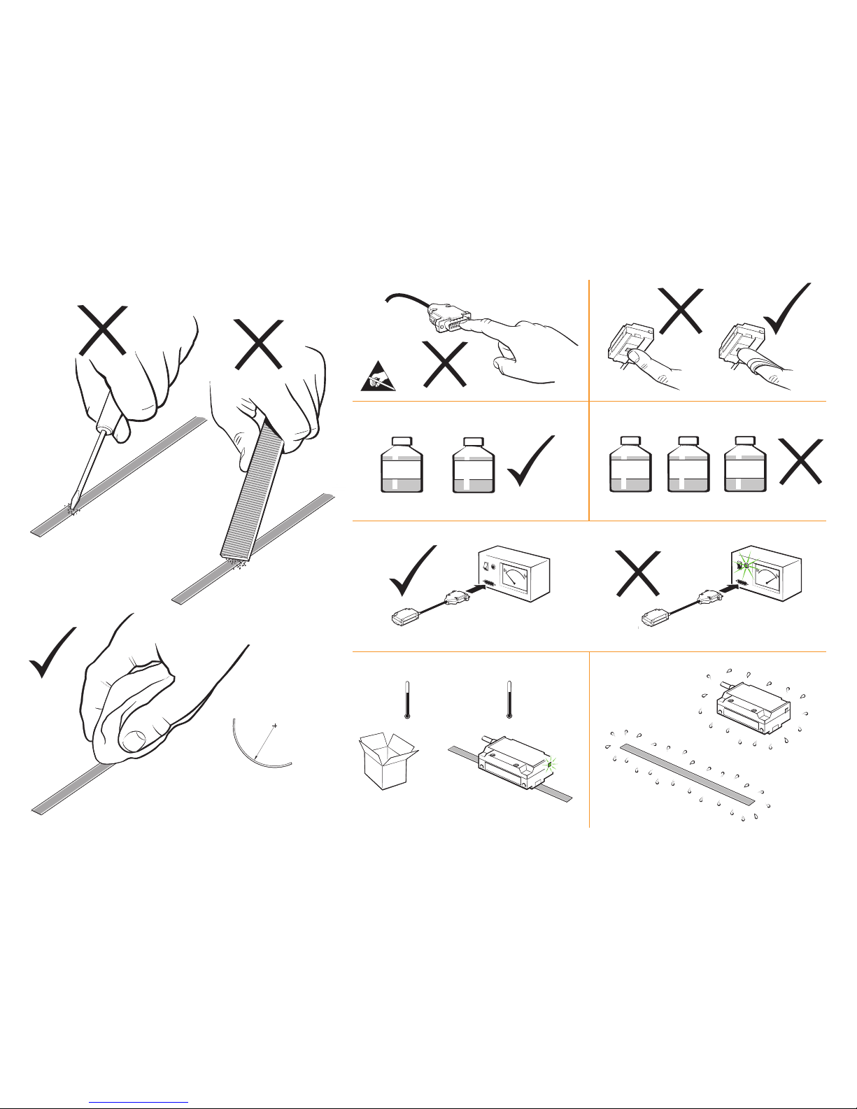
Storage and handling
N-heptane
CH3(CH2)5CH
3
Propan-2-ol
CH
3
CHOHCH
3
Acetone
CH3COCH
3
Methylated
Spirits
Chlorinated
Solvents
RGS20 – 100 mm
NOTE: Ensure self-adhesive
tape is on outside of bend.
Minimum bend radius
Operating
Storage
System
+55 °C
0 °C
System
+70 °C
−20 °C
Humidity
95% relative humidity
(non-condensing)
to EN 60068-2-78
Page 5
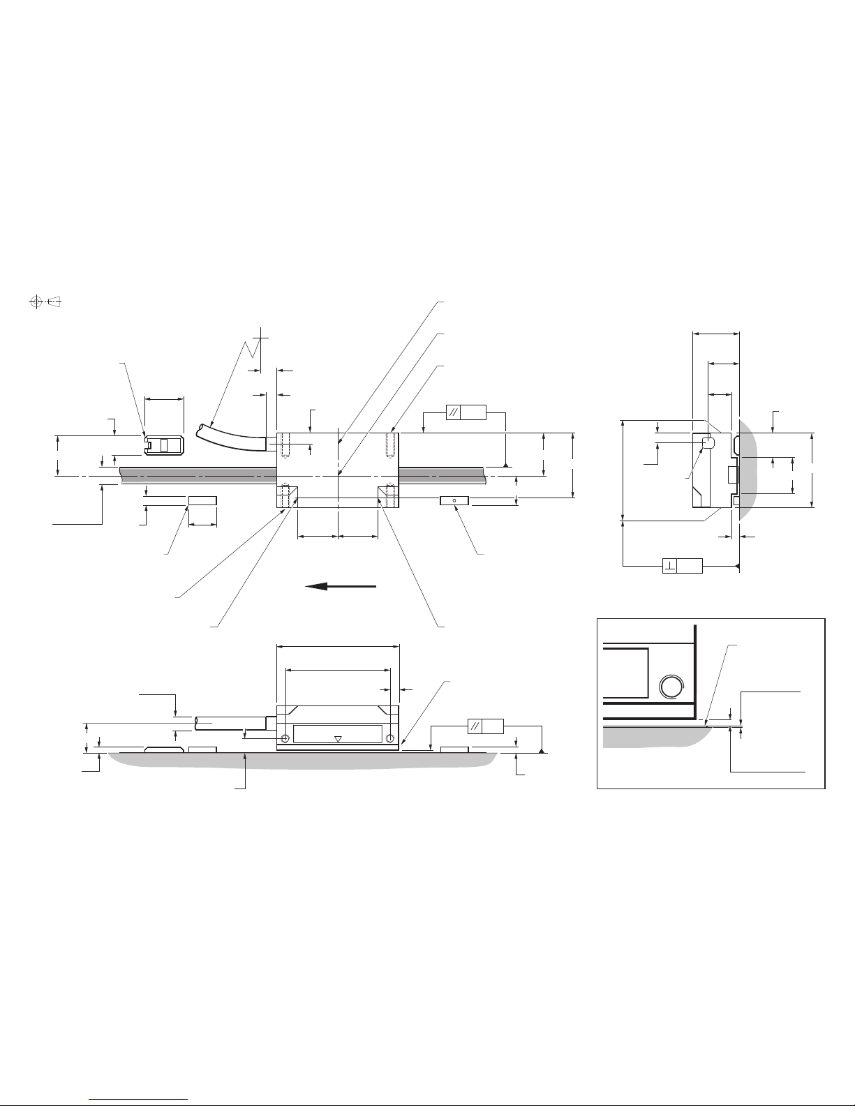
R>50 dynamic bend radius
R>10 static bend radius
>6
4
4
Reference mark sensor position
Optical centre
2 holes M3 x 0.5 x 9.5 deep
‡
(Yaw tol. ± 0.5°)
0.38
15.5
10
Q limit switch sensor position
Q limit switch actuator
(
A-9531-0251)
Mount dimple up
(size as P actuator)
(Roll tol. ± 1°)
0.13
14.6
P limit switch sensor position
2 holes M3 x 0.5 x 7.5 deep
‡
P limit switch actuator
(A-9531-0251)
Dimple to substrate
14.5
7
14
10.6
*
2.2
*
Ø4.7 max
5
*
2
*
(Pitch tol. ± 1°)
0.8
44
38
3
Readhead to
scale clearance
Rideheight 0.8 ± 0.1
A
Detail A
Scale surface
7.6
†
3
*
13
9
27
3.6
11.6
17
*
*
Dimensions measured from substrate. †Alternative mounting faces
‡
The recommended thread engagement is 5 mm. The recommended tightening torque is between 0.5 and 0.7 Nm.
Set-up LED
23.5
Arrow indicates forward direction
of readhead relative to scale
Scale thickness:
0.2 (RGS20-S)
0.3 (RGS20-P)
14.6
3
RGH22 RGS20 installation guide
RGH22 readhead installation drawing
Dimensions and tolerances in mm
3
10.5
6 (RGS20-S)
6.3 (RGS20-P)
Reference mark actuator
Epoxy mounted
(A-9531-0250)
Page 6

4
RGH22 RGS20 installation guide
RGS20 scale installation drawing
Dimensions and tolerances in mm
NOTE: The surface roughness of the scale mounting surface must be ≤3.2 Ra.
The parallelism of the scale surface to the axis of motion (readhead rideheight variation) must be within 0.05 mm.
Overall length (ML + 70)
Scale length (ML + 40)
Measuring length (ML)
Readhead optical centreline
Reference mark sensor position (inside readhead)
0.5
0.2/100
F
>5
>5
<10
30
13
6 (RGS20-S)
6.3 (RGS20-P)
F = axis of motion
22
14
8
10
5
Optional bolted reference mark actuator
(A-9531-0287)
<10
Q limit
P limit
Reference mark actuator position range
>3
>3
Page 7

End clamps
A-9523-4015 is an end clamp kit designed to be used with Renishaw RGS scale.
IMPORTANT: End clamps should be used to ensure positional stability of the scale and
reference mark repeatability.
NOTE: End clamps can be mounted before or after readhead installation.
Ensure that excess glue is wiped away from scale as it may affect the readhead signal level.
3
The end clamp features two small regions
of contact adhesive. These will temporarily
hold the end clamp in position while the
glue cures. Remove the backing tape
from either side.
15 mm
1
Remove the lacquer coating from the
last 15 mm of each end of the scale
with a knife and clean with one of
the recommended solvents
(see ‘Storage and handling’).
4
Immediately position end clamp
over the end of the scale.
Allow 24 hours at 20 °C
for full cure.
2
Thoroughly mix up a sachet of glue
(A-9531-0342) and apply a small amount
to the underside of the end clamp.
RGA22G - scale applicator (recommended for shorter axes or where space is limited)
The RGA22G scale applicator (A-9531-0239) is designed specically for installing RGS20-S scale for use with
the RGH22 readhead. When installing RGS20-P scale use scale applicator (A-9531-3528).
1
Allow scale to acclimatize to installation environment prior to installation.
2
Mark out ‘START’ and ‘FINISH’ points for the scale on the axis substrate. Ensure that there is room for the
end clamps (see ‘RGS20 installation drawing’).
3
Thoroughly clean and degrease the substrate using recommended solvents (see 'Storage and handling').
Allow substrate to dry before applying scale.
4
Mount the scale applicator to the readhead mounting bracket using M3 screws. Place the shim supplied
with the readhead between the applicator and substrate to set the nominal height.
NOTE: Scale applicator can be mounted either way round
to enable easiest orientation for scale installation.
5
Move axis close to scale start position, leaving enough room for the scale to be inserted through the
applicator, as shown below.
6
Begin to remove the backing paper from the scale
and insert scale into the applicator up to the
‘START’ point (as shown).
Ensure backing tape is routed
under the splitter screw.
Scale application
RGA22 - scale applicator (recommended for longer axes)
The RGA22 scale applicator kit (A-9531-0265) is designed specically
for installing RGS20-S scale for use with the RGH22 readhead.
When installing RGS20-P scale use applicator kit (A-9531-0280).
For instructions on how to use the RGA22 please refer to the
‘RGA22 scale applicator User’s guide’ (M-9531-0297).
Backing paper
Scale
8
Slowly and smoothly move the applicator through the entire axis of travel, ensuring the backing
paper is pulled manually from the scale and does not catch under the applicator.
9
Remove applicator and, if necessary, adhere the remaining scale manually.
Apply rm nger pressure via a clean lint-free cloth along the length of the scale after application
to ensure complete adhesion
10
Clean scale using Renishaw scale cleaning wipes (A-9523-4040) or a clean, dry, lint-free cloth.
11
Fit end clamps (see ‘End clamps’ section).
12
Allow 24 hours for complete adhesion of scale before tting reference mark and limit magnets.
START
Direction of scale application
Splitter screw
7
Apply nger pressure to the scale at the ‘START’ point, using a clean lint-free cloth, to ensure scale end
adheres well to the substrate.
M3 mounting holes
‘START’ point
5
RGH22 RGS20 installation guide
Page 8

6
RGH22 RGS20 installation guide
Reference mark and limit switch actuator installation
To aid location of reference mark and limit switches,
the orange shim should be used as shown.
Reference mark and limit switch actuators can be
mounted independently from each other,
but within the limits specied by the
relevant installation drawing.
Limit switch actuator
Reference mark actuator
Ensure that excess glue does not enter the reference mark actuator adjustment mechanism.
Single limit switches
For single limit switch detection, limit switch actuator should be mounted with the dimple uppermost.
Dual limit switches
Some versions of the RGH22 are congured to detect dual limit switch actuators.
NOTE: Refer to RGH22 installation drawing for limit switch actuator positioning.
Reference mark actuators
Reference marks provide a repeatable ‘datum position’ for the readhead.
Actuators are available in either bolted or glued formats (see below)
Limit switch actuators
There are several different size limit switch actuators available:
A-9531-2054
50 mm limit switch
actuator
A-9531-2052
24.4 mm limit switch
actuator
A-9531-0251
10 mm limit switch
actuator
A-9531-0250
Epoxy-mounted
reference mark actuator
A-9531-0287
Screw-mounted
reference mark actuator
Readhead mounting and alignment
Mounting brackets
The bracket must have a at mounting surface and should provide adjustment to enable conformance to the
installation tolerances, allow adjustment to the rideheight of the readhead, and be sufciently stiff to prevent
deection or vibration of the readhead during operation.
Readhead set-up
Ensure that the scale, readhead optical window and mounting face are clean and free from obstructions.
To set nominal rideheight, place the blue or orange spacer with the aperture directly under the optical
centre of the readhead to allow normal LED function during set-up procedure. The orange spacer also
helps to position readhead with respect to offset and yaw relative to the scale
NOTE: Ensure readhead xing screws are tightened to 0.5 Nm - 0.7 Nm.
Adjust the readhead to achieve a solid Green LED. When correctly installed the set-up LED remains Green
along the full axis of travel.
An external set-up signal (X or VX) is also available on RGH22 readheads for use where the LED is not
visible. In this case, 5 V indicates optimum set-up,
while a 0 V signal indicates that the
set-up should be adjusted.
Green Orange Red
Ya w
0° ± 0.5°
Pitch
0° ± 1°
Roll
0° ± 1°
0.8 ± 0.1 mm
Rideheight
orange spacer
or
blue spacer
Page 9

Reference mark set-up
To ensure unidirectional repeatability, the reference mark requires phasing with the scale in the direction
of normal datuming operation.
A reference pulse is output in both directions, but repeatability is guaranteed only in the phased direction.
The readhead should be set up correctly ensuring a green LED indication over the full length of travel.
The reference mark actuator should be installed as shown on the installation drawing.
NOTE: It is recommended that a datum procedure is performed as part of any power-up sequence to
ensure the correct datum position is recorded.
NOTE: Reference mark output is synchronised with the incremental channels, giving unit of resolution
pulse width. For further details see RGH22 Data sheet (Part number L-9517-9676).
Phasing procedure
The readhead must be moved over the reference mark in the direction to be used for the datuming
operation. The reference mark is phased correctly when the set-up LED ashes red for 0.25 seconds.
If it ashes orange or goes blank, the reference mark adjuster screw should be turned anti-clockwise
by
1
8
turn and the procedure repeated until a red ash is obtained.
1
8
turn
Red Orange Blank
LED ash during reference mark traverse only
*
NOTE: Dual limit versions (P, Q, R, S and H) utilise the black wire (pin 11) as the P limit output.
The ‘E’ alarm signal on these versions is only available at the orange wire as a single-ended E- output.
Dual limit readheads are only available with F, D, or X terminations.
Alarm
For RGH22D, X, Z, P, Q, R, - alarm asserted when signal amplitude <15%.
For RGH22Y, S, H - alarm asserted when: - Signal amplitude >150% - Readhead exceeds specied maximum speed
Also, outputs are 3-stated at signal amplitude <15%
Output signals
RGH22 D, X, Z, Y, H, P, Q, R, S, RS422A digital
7
RGH22 RGS20 installation guide
12 pin circular plug (termination code R)
52
28
15 pin D type plug (termination code D)
40
16
52
Limit switch
Limit switch detection is entirely independent of other readhead functions - the signal is only output
when the readhead is positioned over the limit switch actuator.
Function Signal Colour
15 way D-type
plug
(D)
12 way circular
(R)
16 way in-line
connector
(X)
Power
5 V
Brown 7 2 A
Brown (link) 8 12 M
0 V
White 2 10 B
White (link) 9 11 N
Incremental signals
A
+ Green 14 5 G
- Yellow 6 6 D
B
+ Blue 13 8 R
- Red 5 1 F
Reference mark
Z
+ Violet 12 3 K
- Grey 4 4 O
Limit switch
*
Q Pink 10 – H
Alarm
E
+ Black 11 9 I
- Orange 3 7 P
External set-up
X Clear 1 – E
Shield
Inner Green / Yellow 15 11 (link) L
Outer – Case Case Case
In-line connector plug (termination code X)
66
17
Page 10

*
NOTE: Dual limit versions (A) utilise the clear wire (pin 7) as the VP limit output. The VX external set-up signal on these
versions is not available. Dual limit readheads are only available with F, L or X terminations.
†
Only connected with option 17 ††Only connected with option 18
Output signals (continued)
RGH22 A, B 1 Vpp analogue
12 pin circular coupling plug (termination code W)
52
28
In-line connector plug (termination code X)
66
17
‡
Reference mark uni-directional operation
The RGH22 reference mark output is not repeatable in both directions. Certain controllers will ag an error
when they see different reference mark positions in the forward and reverse directions.
BID DIR pins allow the readhead to be congured to ignore the reference pulse output in the unphased
direction (see section Reference mark set-up).
8
RGH22 RGS20 installation guide
Analogue readheads
RGH22A and B – 4 m/s (-3dB)
Speed
Digital readheads
Non-clocked output readheads
x 4 safety factor
Encoder velocity (m/s)
Resolution (µm)
Clocked output readheads
The RGH22Y, S, and H readheads are available with a variety of different clocked outputs.
Customers must ensure they comply with the lowest recommended counter input frequency.
BID/DIR connections
Function Signal Colour
15 way
D-type plug
(L)
12 way
circular
(V)
12 way
circular
coupling
(W)
16 way
in-line
connector
(X)
Power
5 V
Brown 4 2 2 A
Brown (link) 5 12 12 M
0 V
White 12 10 10 B
White (link) 13 11 11 N
Incremental signals
V
1
+ Red 9 5 5 F
- Blue 1 6 6 R
V
2
+ Yellow 10 8 8 D
- Green 2 1 1 G
Reference mark
V
0
+ Violet 3 3 3 K
- Grey 11 4 4 O
Limit switch
*
V
q
Pink 8 N/C N/C H
External set-up
V
x
Clear 7 N/C N/C E
Reference mark
uni-directional
operation
‡
BID Black 6
9
†
9
††
I
DIR Orange 14
7
†
7
††
P
Shield
Inner Green/Yellow 15 11 (link) 11 (link) L
Outer – Case Case Case Case
12 pin circular plug (termination code V)
52
28
15 pin D type plug (termination code L)
40
16
52
BID / DIR connection
To:- Reference mark output direction
For bi-directional operation (normal)
BID +5 V or not connected
Forward and reverse
DIR Do not connect
BID / DIR connection
To:- Reference mark output direction
For uni-directional operation
BID 0 V
DIR +5 V or not connected Forward only
DIR 0 V Reverse only
Head type Maximum speed (m/s) Lowest recommended counter input frequency (MHz)
D and P (5 µm) 10
X and Q (1 µm) 5
Z and R (0.5 µm) 3
Options
Maximum speed (m/s)
Lowest recommended counter input
frequency (MHz)
Head type
Y and S
(0.1 µm)
H
(50 nm)
61 1.3 0.6 20
62 0.7 0.3 10
63 0.35 0.15 5
Page 11

9
RGH22 RGS20 installation guide
Electrical connections
Grounding and shielding
*
Maximum extension cable length
RGH22A and B -100 m, RGH22D, X, Z, P, Q and R - 50 m, RGH22Y, S and H -20 m
RGH22
Customer
electronics
Extension cable
*
Inner shield
Outer shield
Output
signals
0 V
5 V
IMPORTANT: The outer shield should be connected to the machine earth (Field Ground). The inner shield should be connected
to 0 V. Care should be taken to ensure that the inner and outer shields are insulated from each other. If the inner and outer shields
are connected together, this will cause a short between 0 V and earth, which could cause electrical noise issues.
Recommended signal termination
Digital outputs - RGH22D, X, Z, Y, H, P, Q, R and S
Analogue output - RGH22 A, B
V0 V1 V2+
V0 V1 V2-
120 Ω
Standard RS422A line receiver circuitry.
Capacitors recommended for improved noise immunity.
†
Only required on alarm channel E for fail safe operation.
Customer
electronics
120 Ω
A B Z E-
Cable Z0 = 120 Ω
Readhead
A B Z E+
0 V
0 V
220 pF
220 pF
Limit output
5 V - 25 V
R
P Q Vp V
q
Select R so that maximum current does not exceed 20 mA.
Alternatively, use a relay or opto-isolator.
1k
†
0 V
1k
†
Page 12

10
RGH22 RGS20 installation guide
Output specications
Digital output signals - type RGH22D, X, Z, Y, H, P, Q, R and S
Form - Square wave differential line driver to EIA RS422A (except limit switches P, Q and external set-up signal X)
Synchronised pulse Z, duration as resolution S.
Repeatability of position (uni-directional) maintained within
±10 °C from installation temperature and for speed <250 mm/s.
For RGH22Y, S, H only Z pulse re-synchronised at power-up
with any one of the quadrature states (00, 01, 11, 10).
Actuation device A-9531-0250 or A-9531-0287
Reference
†
Incremental
†
2 channels A and B in quadrature (90° phase shifted)
Signal period P
Resolution S
A
B
Z
Actuation device A-9531-0251, A-9531-2052 or A-9531-2054.
*Dual limit available with flying lead, 15 pin D connector or in-line X connector only.
†Inverse signals not shown for clarity.
Limit open collector output
Single limit D, X, Z, Y
Dual limit P, Q, R, S, H
*
Length of actuating magnet
Repeatability
<0.1 mm typical
P Q
Length of actuating magnet
Repeatability
<0.1 mm typical
Q
Asynchronous pulse Q
Between 50% and 70% signal level, X is a
duty cycle, 20 µm duration.
Time spent at 5 V increases with signal level.
At >70% signal level X is nominal 5 V.
External set-up
voltage at X
5 (nom)
50% 70%
100%
0
0
signal level
20 ms minimum
E
Alarm
RGH22D, P, X, Q, Z and R
Alarm output asserted when <15% signal
RGH22Y, S and H
Options 61, 62 and 63
Single ended line driven output alarm asserted when >150% signal or overspeed (RGH22S and H only).
Differential line driver output alarm asserted when >150% signal or overspeed (RGH22Y only).
3-state output alarm asserted when <15% signal.
Line driven alarm output
†
E- only on dual limit readheads (RGH22P, Q, R, S and H only)
3-state output
Differentially transmitted signals forced open circuit for >20 ms when alarm conditions valid.
Asynchronous pulse P, Q
Model P (µm) S (µm)
RGH22D and P 20 5
RGH22X and Q 4 1
RGH22Z and R 2 0.5
RGH22Y and S 0.4 0.1
RGH22H 0.2 0.05
Option Alarm type
00A Differential line driven output (RGH22D, X and Z only)
00A Single ended line dr iven output (RGH22P, Q and R only)
20A 3-state output
Page 13

11
RGH22 RGS20 installation guide
Output specications (continued)
Analogue output signals - type RGH22B and A (1Vpp)
Actuation device A-9531-0251, A-9531-2052 or A-9531-2054.
Limit open collector output
Single limit RGH22B
Dual limit RGH22A
Asynchronous pulse Vp V
q
Length of actuating magnet
Repeatability
<0.1 mm typical
V
q
Asynchronous pulse V
q
Between 50% and 70% signal level,
VX is a duty cycle, 20 µm duration.
Time spent at 5 V increases with signal level.
At >70% signal level VX is nominal 5 V.
External set-up
voltage at V
X
5 (nom)
50%
70%
100%
0
0
signal level
20 µm
90°
108°-18°
0°
Incremental 2 channels V
1
and V2 differential sinusoids in quadrature (90° phase shifted)
Differential pulse V0 - 18° to 108°.
Duration 126° (electrical).
Repeatability of position (uni-directional) maintained
within ±10 °C from installation temperature and for
speed <250 mm/s.
Actuation device A-9531-0250 or A-9531-0037
0.6 to 1.2 Vpp with
green LED indication
and 120 Ω termination.
Reference
(V1 +) - (V1-)
(V2 +) - (V2-)
0.8 to 1.2 Vpp
(V0+) - (V0-)
P Q
Length of actuating magnet
Repeatability
<0.1 mm typical
Page 14

12
RGH22 RGS20 installation guide
General specications
Power supply 5 V ± 5% 120 mA (typical), 200 mA RGH22Y, S and H
NOTE: Current consumption figures refer to unterminated readheads.
For digital outputs a further 25 mA per channel pair (e.g. A+, A-) will
be drawn when terminated with 120 Ω.
For analogue outputs a further 20 mA will be drawn when terminated
with 120 Ω.
Power from a 5 V dc supply complying with the requirements for SELV
of standard IEC BS EN 60950-1.
Ripple 200 mVpp@frequency up to 500 kHz maximum.
Temperature Storage −20 °C to +70 °C
Operating 0 °C to +55 °C
Humidity 95% relative humidity (non-condensing) to EN 60068-2-78
Sealing IP50
Acceleration Operating 500 m/s2, 3 axes
Shock Non-operating 1000 m/s2, 6 ms, ½ sine, 3 axes
Vibration Operating 100 m/s2 max @ 55 Hz to 2000 Hz, 3 axes
Mass Readhead 45 g
Cable 38 g/m
Cable 12 core, double shielded, maximum diameter 4.7 mm.
Flex life >20 x 106 cycles at 50 mm bend radius.
Renishaw encoder systems have been designed to the relevant EMC standards, but must be correctly
integrated to achieve EMC compliance. In particular, attention to shielding arrangements is essential.
Scale specications
Scale type RGS20-S Reective gold plated steel tape with protective lacquer coating.
Adhesive backing tape allows direct mounting to the machine substrate.
RGS20-P Reective gold plated steel tape with tough polyester coating for
applications using harsh solvents.
Adhesive backing tape allows direct mounting to the machine substrate.
Scale period 20 µm
Linearity RGS20-S ±3 µm /m
RGS20-P ±5 µm/ m
Scale length Up to 50 m (>50 m by special order)
Form (H x W) RGS20-S 0.2 mm x 6 mm (includes adhesive)
RGS20-P 0.3 mm x 6.3 mm (includes adhesive)
Substrate materials Metals, ceramics and composites with expansion coefcients
between 0 and 22 µm/m/°C
(steel, aluminium, Invar, granite, ceramic etc.)
Coefcient of thermal expansion Matches that of substrate material when scale ends are xed by
epoxy mounted end clamps
End xing Epoxy mounted end clamps (A-9523-4015) using 2 part epoxy
adhesive (A-9531-0342)
Scale end movement <1 µm over temperature range −20 °C to +50 °C
Temperature Operating −10 °C to +120 °C.
Minimum installation 10 °C
Storage −20 °C to +70 °C.
Humidity 95% relative humidity (non-condensing) to EN 60068-2-78
Page 15

Renishaw plc
New Mills, Wotton-under-Edge,
Gloucestershire GL12 8JR
United Kingdom
T +44 (0)1453 524524
F +44 (0)1453 524901
E uk@renishaw.com
www.renishaw.com
*M-9531-9818-01*
For worldwide contact details,
please visit our main website at
www.renishaw.com/contact
RENISHAW® and the probe symbol used in the RENISHAW logo are registered trade marks
of Renishaw plc in the United Kingdom and other countries.
apply innovation and names and designations of other Renishaw products and technologies
are trade marks of Renishaw plc or its subsidiaries.
© 2001-2018 Renishaw plc All rights reserved Issued 1018
 Loading...