

Page 1

Installation and user’s guide
M-9904-1122-09-A
RCU10 quadrature compensation unit
Page 2

Document information
Document number: M-9904-1122-09-A
Issue date: 03 2019
© 2004-2019 Renishaw plc. All rights reserved.
Care of equipment
The Renishaw RCU10 compensation system and
associated products are precision instrumentation
products and components and must therefore be
treated with care.
Changes to Renishaw products
Renishaw plc reserves the right to improve,
change or modify its products and documentation
without incurring any obligation to make changes
to Renishaw equipment previously sold or
distributed.
Disclaimer
RENISHAW HAS MADE CONSIDERABLE
EFFORTS TO ENSURE THE CONTENT OF
THIS DOCUMENT IS CORRECT AT THE
DATE OF PUBLICATION BUT MAKES NO
WARRANTIES OR REPRESENTATIONS
REGARDING THE CONTENT. RENISHAW
EXCLUDES LIABILITY, HOWSOEVER
ARISING, FOR ANY INACCURACIES IN THIS
DOCUMENT.
Trademarks
RENISHAW® and the probe emblem used in the
RENISHAW logo are registered trademarks of
Renishaw plc in the UK and other countries.
apply innovation is a trademark of Renishaw plc.
All other brand names and product names used
in this document are trade names, service marks,
trademarks, or registered trademarks of their
respective owners.
Safety
This manual gives recommendations for the
safe installation and configuration of the RCU10
compensator system, and associated ancillary
products.
It is the sole responsibility of the OEM/retrofit
company to ensure that, in safety critical
applications, any failure or deviation from
expected operation of this product, howsoever
caused, shall not cause the machine to become
unsafe.
It is the machine supplier’s responsibility to
ensure that the user is made aware of any
hazards that may be involved in the operation
of their machine, including those covered in
Renishaw product documentation, and to ensure
that adequate guards and safety interlocks are
provided.
This manual suggests a number of safety
measures that can be included in machine
design. However, it is the sole responsibilty of the
OEM/system integrator to specify and integrate
measures suitable for the application.
Symbol definition
The following symbol is used in this manual and
in the software to indicate areas requiring special
attention:
WARNING: Information that is vital for
!
Warranty
Renishaw plc warrants its equipment provided
that it is installed and operated exactly as defined
in associated Renishaw documentation.
Claims under warranty must be made from
authorised service centres only, which may be
advised by the supplier or distributor.
FCC
This device complies with part 15 of the FCC
Rules. Operation is subject to the following two
conditions: (1) This device may not cause harmful
interference and (2) this device must accept any
interference received, including interference that
may cause undesired operation.
This equipment has been tested and found
to comply with the limits for a Class A digital
device, pursuant to Part 15 of the FCC Rules.
These limits are designed to provide reasonable
protection against harmful interference when
the equipment is operated in a commercial
environment. This equipment generates, uses,
and can radiate radio frequency energy and,
if not installed and used in acordance with
the instruction manual, may cause harmful
interference to radio communications. Operation
of this equipment in a residential area is likely to
cause harmful interference in which case the user
will be required to correct the interference at his
own expense.
The user is cautioned that any changes or
modifications not expressly approved by
Renishaw plc or authorized representative could
void the user’s authority to operate the equipment.
EC compliance
Renishaw plc declares that the RCU10
compensator system and transmitters comply
with the applicable directives, standards and
regulations. A copy of the full EC Declaration of
Conformity is available at the following address:
www.renishaw.com/RLECE
the safe installation and operation of the
RCU10 system.
Page 3

WEEE
The use of this symbol on Renishaw products
and/or accompanying documentation indicates
that the product should not be mixed with
general household waste upon disposal. It is the
responsibility of the end user to dispose of this
product at a designated collection point for waste
electrical and electronic equipment (WEEE) to
enable reuse or recycling. Correct disposal of
this product will help to save valuable resources
and prevent potential negative effects on the
environment. For more information, please
contact your local waste disposal service or
Renishaw distributor.
Battery disposal
REACH
Information required by Article 33(1) of
Regulation (EC) No. 1907/2006 (“REACH”)
relating to products containing substances of very
high concern (SVHCs) is available at:
www.renishaw.com/REACH
RoHS compliance
Compliant with EC directive 2011/65/EU (RoHS).
The use of this symbol on the batteries,
packaging or accompanying documents indicates
that used batteries should not be mixed with
general household waste. Please dispose of
the used batteries at a designated collection
point. This will prevent potential negative effects
on the environment and human health which
could otherwise arise from inappropriate waste
handling. Please contact your local authority or
waste disposal service concerning the separate
collection and disposal of batteries. All lithium and
rechargeable batteries must be fully discharged
or protected from short circuiting prior to disposal.
Packaging
Packaging
components
Outer box Cardboard -
Insert Cardboard -
Material 94/62/EC
code
PA P 20
70% recycled
material
PA P 20
70% recycled
material
94/62/EC
number
Bags Low density
polyethylene
LDPE 4
Page 4

General safety notice i
General safety notice
The Renishaw laser encoder and compensator systems are designed for integration into
the primary position feedback loop of a motion system. It is essential that the system is
installed in accordance with the instructions in the installation guide and it is the
responsibility of the system integrator to ensure that, in the event of a failure of any part of
the Renishaw system, the motion system remains safe.
In the case of motion systems with powers or speeds capable of causing injury, it is
essential that appropriate safety protection measures are included in the machine design.
Further guidance on this can be found in the European Standard EN292 “Safety of
machinery – Basic concepts, general principles for design”. It is the sole responsibility of
the OEM/system integrator to select the safety measures appropriate for their application.
The following is a list of measures that should be considered as part of that process.
1. The Renishaw system includes an Error signal output. The control system must be
designed to stop the axis motion if this error output is asserted. In addition to the
Error signal, the position feedback signals can also be configured to go tristate
(open circuit) under fault conditions. Some controllers can be programmed to detect
this, thereby providing a further level of protection in case of failure of the error
signal output (see item 3 below). If the controller is not capable of detecting open
circuit position feedback signals, this option must not be enabled.
2. The axis must include physical limit switches which, when tripped, will stop axis
motion before damage occurs (soft limits alone are insufficient). Note that in the
case of thermally compensated systems, positional corrections of several hundred
ppm are possible. This should be taken into account when defining the relative
positions of soft and hard axis limits.
3. Cable breakage detection (encoder disconnect). The position feedback and Error
signal lines are all provided as differential line driven pairs. Failure in the cable or
failure of the line drivers can be detected by checking that these differential pairs are
always being driven in opposing states. If the lines are not in opposing states, the
motion must be stopped.
4. Motor torque monitoring. If the motor torque exceeds an expected limit, the axis of
motion must be stopped.
5. The machine must include an emergency stop button.
6. Following error detection, if the difference between the controller demand position
and the axis feedback position exceeds an expected limit, then the axis motion must
be stopped.
7. Guards, viewing windows, covers and interlocks may be used to prevent user
access to hazardous areas, and to contain ejected parts or materials.
8. If the machine includes an independent tacho (velocity) feedback system, this
should be cross-checked with the position feedback. For example, if the tacho
indicates the axis is moving, but the position feedback doesn’t, then the axis motion
must be stopped.
Page 5

ii General safety notice
9. In the case of synchronised parallel motion systems (for example twin rail gantry
drive systems), the relative positions of master and slave axes should be monitored.
If the difference in their positions exceeds an expected limit, then axis motion must
be stopped.
Note: In the case of measures 6 – 9, the limits need to be selected carefully depending on
the application and the type of position compensation selected to avoid false alarms.
For further advice consult the appropriate machinery safety standards.
Page 6

Contents iii
Contents
Section 1 System overview
1.1 Introduction ............................................................................................................ 1-2
1.2 System overview ................................................................................................... 1-2
1.3 Compensation functions ........................................................................................ 1-4
1.3.1 Scale factor ............................................................................................... 1-4
1.3.2 Air refractive index compensation ............................................................. 1-4
1.3.3 Encoder thermal expansion compensation ............................................... 1-5
1.3.4 Workpiece thermal expansion compensation ........................................... 1-5
1.3.5 Structure thermal compensation ............................................................... 1-7
1.4 Operational functions ............................................................................................. 1-8
1.4.1 Selectable parameter tables ..................................................................... 1-8
1.4.2 Compensation buffering ............................................................................ 1-8
1.5 System components .............................................................................................. 1-9
1.6 Installation procedure overview ........................................................................... 1-11
Section 2 System design
2.1 Requirements ........................................................................................................ 2-2
2.2 Sensors and sensor networks ............................................................................... 2-3
2.2.1 Environment sensors................................................................................. 2-3
2.2.2 Sensor network connection ....................................................................... 2-4
2.3 Electrical connections ............................................................................................ 2-5
2.3.1 Connector positions................................................................................... 2-5
2.3.2 Connector functions .................................................................................. 2-6
J1 – 24 V dc power .................................................................................... 2-6
J2 – Controller output ................................................................................ 2-6
J3 – Encoder input .................................................................................... 2-6
J4 – Reference switch port ........................................................................ 2-7
J7 – Auxiliary I/O ....................................................................................... 2-8
J8 – PC port .............................................................................................. 2-9
2.4 Velocity/resolution/bandwidth considerations ........................................................ 2-9
2.4.1 Encoder input frequency ......................................................................... 2-10
2.4.2 Output frequency ..................................................................................... 2-10
2.5 Referencing ......................................................................................................... 2-12
2.5.1 Signal format and re-synchronisation ...................................................... 2-12
2.5.2 Referencing options ................................................................................ 2-14
2.6 RCU10 component mounting .............................................................................. 2-17
2.6.1 RCU10-XX-XX or RCU10-PX-XX ........................................................... 2-17
2.6.2 Air temperature sensor ............................................................................ 2-18
2.6.3 Material temperature sensor ................................................................... 2-19
2.6.4 Sensor distribution box ............................................................................ 2-20
Section 3 Kit configuration and part identification
3.1 Defining kit numbers .............................................................................................. 3-2
3.2 Kit numbers and part identification ........................................................................ 3-3
3.2.1 RCU10 kit numbers (laser encoder based systems) ................................ 3-3
3.2.2 RCU10 kit numbers (non-laser encoder based systems) ......................... 3-4
3.3 Additional components and part identification ....................................................... 3-5
Page 7

iv Contents
Section 4 System installation
4.1 System installation ................................................................................................. 4-2
4.1.1 Hardware installation and initial power-up ................................................ 4-2
4.1.2 RCU10 address set-up .............................................................................. 4-2
4.1.3 Electrical ins ta llation .................................................................................. 4-4
4.1.4 RCU CS settings ....................................................................................... 4-4
4.2 System configuration ............................................................................................. 4-5
4.2.1 System configuration ................................................................................. 4-6
4.2.2 Sensor network configuration .................................................................... 4-7
4.2.3 Compensation settings configuration ........................................................ 4-8
4.2.4 Parameter settings configuration ............................................................. 4-13
4.2.5 Transmitting the configuration ................................................................. 4-15
4.3 Configuration validation ....................................................................................... 4-16
Section 5 Controller integration
5.1 Introduction ............................................................................................................ 5-2
5.2 Safety function testing ........................................................................................... 5-2
5.2.1 Encoder error testing ................................................................................. 5-2
5.2.2 RCU10 error testing................................................................................... 5-3
5.2.3 Testing environment sensors .................................................................... 5-5
5.2.4 Auxiliary I/O connector input functions ...................................................... 5-6
5.2.5 Reference mark connector function .......................................................... 5-8
5.2.6 Encoder considerations ............................................................................. 5-9
5.2.7 Integration procedure .............................................................................. 5-10
5.2.8 Making corrections .................................................................................. 5-10
5.2.9 Closing the control loop ........................................................................... 5-11
5.2.10 Motor drive tuning .................................................................................... 5-11
5.2.11 Referencing the system ........................................................................... 5-12
Section 6 Operation
6.1 Standard operation ................................................................................................ 6-2
6.2 RCU CS status during operation ........................................................................... 6-2
6.2.1 Compensation display ............................................................................... 6-3
6.2.2 Sensor display ........................................................................................... 6-4
6.2.3 Diagnostics display .................................................................................... 6-5
6.3 General maintenance ............................................................................................ 6-6
Appendix A RCU10 system specifications
A.1 RCU10 system performance ................................................................................. A-2
A.2 Component performance ....................................................................................... A-4
A.2.1 Compensation unit..................................................................................... A-4
A.2.2 Air sensor .................................................................................................. A-5
A.2.3 Material sensor .......................................................................................... A-5
A.2.4 Pressure sensor ........................................................................................ A-5
Page 8

Contents v
Appendix B Connector pinout and hardware installation details
B.1 Introduction ........................................................................................................... B-2
B.2 24 V dc power (J1) ................................................................................................ B-2
B.2.1 Connector pinout ....................................................................................... B-2
B.2.2 Wiring requirements .................................................................................. B-3
B.3 Controller output (J2) ............................................................................................. B-4
B.3.1 Digital feedback signals ............................................................................ B-4
B.3.1.1 Connector pinout ....................................................................... B-4
B.3.1.2 Wiring requirements .................................................................. B-5
B.3.2 Analogue feedback signals ....................................................................... B-6
B.3.2.1 Connector pinout ....................................................................... B-6
B.3.2.2 Wiring requirements .................................................................. B-7
B.4 Encoder input (J3) ................................................................................................. B-8
B.4.1 Connector pinout ....................................................................................... B-8
B.4.2 Wiring requirements .................................................................................. B-9
B.5 Reference switch port (J4) ................................................................................... B-10
B.5.1 Connector pinout ..................................................................................... B-10
B.5.2 Wiring requirements ................................................................................ B-10
B.6 Auxiliary I/O (J7) .................................................................................................. B-11
B.6.1 Connector pinout ..................................................................................... B-11
B.6.2 Wiring requirements ................................................................................ B-11
B.7 PC port (J8) ......................................................................................................... B-13
B.7.1 Connector pinout ..................................................................................... B-13
B.7.2 Wiring requirements ................................................................................ B-13
B.8 Fastlink port ......................................................................................................... B-14
B.9 Sensors (J5, J6) .................................................................................................. B-14
B.9.1 Connector pinout ..................................................................................... B-14
B.9.2 Wiring requirements ................................................................................ B-15
Appendix C RCU CS
C.1 RCU CS ................................................................................................................. C-2
C.1.1 Overview ................................................................................................... C-2
C.1.2 Access levels ............................................................................................. C-2
C.1.3 Operating modes ....................................................................................... C-3
C.1.4 Configuration data ..................................................................................... C-4
C.2 RCU CS installation ............................................................................................... C-5
C.2.1 System requirements ................................................................................ C-5
C.2.2 Installation procedure ................................................................................ C-6
C.2.3 Screen layout ............................................................................................ C-7
Appendix D Compensation system status information and diagnostics
D.1 Diagnostics ............................................................................................................ D-2
D.1.1 Process overview ...................................................................................... D-2
D.2 Error descriptions .................................................................................................. D-3
D.3 RCU CS information screens ................................................................................ D-4
D.3.1 Compensation system screen ................................................................... D-4
D.3.2 Compensation axis screen ........................................................................ D-8
D.3.3 Sensor data screen ................................................................................... D-9
D.3.3.1 Individual “View status” screen ............................................... D-10
Page 9

vi Contents
D.3.4 Diagnostics ............................................................................................. D-13
D.3.4.1 System status screen .............................................................. D-13
D.3.4.2 RCU diagnostics screen (top display) ..................................... D-14
D.3.4.3 RCU diagnostics – Configuration tab ...................................... D-15
D.3.4.4 Axis diagnostics – Compensation tab ..................................... D-17
D.3.4.5 Axis diagnostics – Communication tab .................................... D-19
D.3.4.6 Axis diagnostics – Sensors tab ............................................... D-21
Appendix E Commissioning tests
E.1 System performance testing .................................................................................. E-2
E.1.1 Prerequisites .............................................................................................. E-2
E.1.2 Test 1 – Linear compensation (air refractive index or encoder scale
compensation) ........................................................................................... E-3
E.1.3 Test 2 – Workpiece thermal expansion compensation ............................. E-4
E.1.4 Test 3 – Workpiece thermal expansion at higher temperatures ............... E-5
E.1.5 Test 4 – Workpiece temperature change at material reference position .. E-5
E.1.6 Test 5 – Static workpiece temperature change at distance ...................... E-6
Appendix F Extended capability
F.1 Extended RCU10 system capability ...................................................................... F-2
F.1.1 Extended system capability ....................................................................... F-2
F.1.2 Extended system status monitoring .......................................................... F-2
F.1.2.1 Extended status monitoring ....................................................... F-2
F.1.3 Axis referencing with extended error lines ................................................ F-4
F.1.4 Controlling workpiece compensation from motion control system output
lines ........................................................................................................... F-5
F.1.4.1 Introduction ................................................................................ F-5
F.1.4.2 Enabling workpiece compensation ............................................ F-5
F.1.4.3 Disabling workpiece compensation ........................................... F-5
F.1.4.4 Suspending workpiece compensation ....................................... F-6
F.1.4.5 Multiple fixturing with workpiece compensation ........................ F-6
F.1.5 Parameter table selection .......................................................................... F-7
F.1.6 Compensation buffering ............................................................................ F-8
F.1.7 Configuration of advanced features .......................................................... F-8
F.1.7.1 Multiple parameter tables .......................................................... F-8
F.1.7.2 Operating with multiple parameter tables .................................. F-9
F.2 RCU CS – Additional functionality ....................................................................... F-12
F.2.1 Additional RCU CS configuration functionality ........................................ F-12
F.2.1.1 Saving the configuration .......................................................... F-12
F.2.1.2 Loading a configuration ........................................................... F-13
F.2.1.3 Setting the PC communication port ......................................... F-14
F.2.1.4 Configuring passwords ............................................................ F-15
F.2.1.5 Logging in as new user............................................................ F-16
F.2.1.6 Rebooting the RCU ................................................................. F-16
F.2.2 Data logging ............................................................................................ F-18
F.2.3 Error logging ............................................................................................ F-20
F.2.3.1 Error log descriptions ............................................................... F-25
Page 10

Contents vii
Appendix G Reference
G.1 Compensation equation overview ........................................................................ G-2
G.1.1 Encoder compensation............................................................................. G-2
G.1.1.1 Definition of position terms ........................................................ G-2
G.1.1.2 Definition of compensation terms .............................................. G-3
G.1.2 Laser compensation ................................................................................. G-5
G.1.2.1 Definition of position terms ........................................................ G-5
G.1.2.2 Definition of compensation terms .............................................. G-6
G.2 Air refraction compensation .................................................................................. G-9
G.3 Worked example – laser compensation ............................................................. G-11
G.3.1 Direction sense setting ........................................................................... G-11
G.3.2 Laser dead path (LO) ............................................................................. G-12
G.3.3 Workpiece thermal expansion compensation (α
G.3.4 Machine structure thermal expansion compensation (T
, Twc, WO).................. G-12
w
, S) ................ G-12
sc
Appendix H Test records
H.1 Installation and configuration checklist .................................................................. H-2
H.2 Installation details .................................................................................................. H-3
H.3 Sensor record/test sheet ....................................................................................... H-5
H.4 Parameter table record sheets .............................................................................. H-7
Page 11

viii Contents
This page is intentionally left blank.
Page 12

System overview 1-1
Section 1
System overview
Contained in this section
1.1 Introduction ............................................................................................................ 1-2
1.2 System overview .................................................................................................... 1-2
1.3 Compensation functions ........................................................................................ 1-4
1.3.1 Scale factor ............................................................................................... 1-4
1.3.2 Air refractive index compensation ............................................................. 1-4
1.3.3 Encoder thermal expansion compensation ............................................... 1-5
1.3.4 Workpiece thermal expansion compensation ........................................... 1-5
1.3.5 Structure thermal compensation ............................................................... 1-7
1.4 Operational functions ............................................................................................. 1-8
1.4.1 Selectable parameter tables ...................................................................... 1-8
1.4.2 Compensation buffering ............................................................................ 1-8
1.5 System components .............................................................................................. 1-9
1.6 Installation procedure overview ........................................................................... 1-11
Page 13

1-2 System overview
1.1 Introduction
This manual covers the installation, configuration and operation of the Renishaw RCU10
real-time quadrature compensator system.
1.2 System overview
The RCU10 real-time quadrature compensation system overcomes environmental error
sources in linear motion systems to improve process accuracy and repeatability. The
RCU10 monitors a machine’s ambient environment, via a network of sensors, and uses
advanced digital signal processing to perform real-time compensation on the position
feedback signals.
The RCU10 can provide:
Refractive index compensation, for laser encoders, using air pressure and
temperature sensors.
Scale thermal expansion compensation, for incremental linear encoders, using
material temperature sensors.
Thermal expansion compensation of machine structure and workpieces, using
material temperature sensors.
Format conversion – digital (A quad B) to analogue (Sin/Cos)
Scale factor conversion – laser wavelength to engineering units
Figure 1.1 – RCU10-P with sensors
Page 14
System overview 1-3
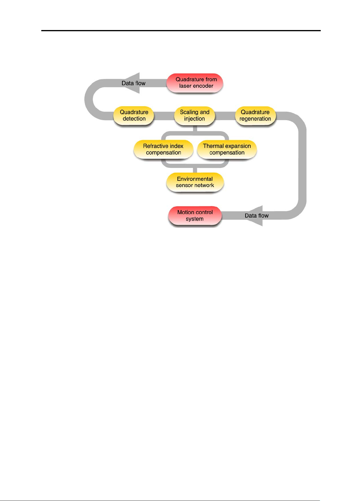
A functional block diagram of the RCU10 is show below:
Figure 1.2 – Internal block diagram of operation when used in conjunction with a
laser encoder
The RCU10 processor accepts digital quadrature, along with the environmental data
collected by factory-calibrated sensors, and calculates the total amount of compensation
necessary to correct the axis position. The required compensation is then applied through
quadrature scaling and injection (addition or removal of quadrature pulses) into the
encoder feedback signal, the total process being completely transparent to the motion
controller. The corrected feedback signals are provided to the motion controller in either
RS422 digital A quad B or analogue Sin/Cos 1 Vpp formats, with a nominal accuracy of
±1 ppm (refractive index only) or ±2 ppm (with 10 ppm/°C material compensation).
The RCU10 compensator is available in two models:
RCU10-P, which contains an internal air pressure sensor
RCU10, which does not contain an air pressure sensor
One compensator is required for each machine axis that is to be compensated.
When laser encoders are being used, one compensator in the system must be an
RCU10-P so that the ambient air pressure can be determined and refractive index
compensation applied. The basic RCU10 may be used for conventional (non-laser)
encoders or for ‘slave’ axes in a laser encoder system.
Page 15
1-4 System overview
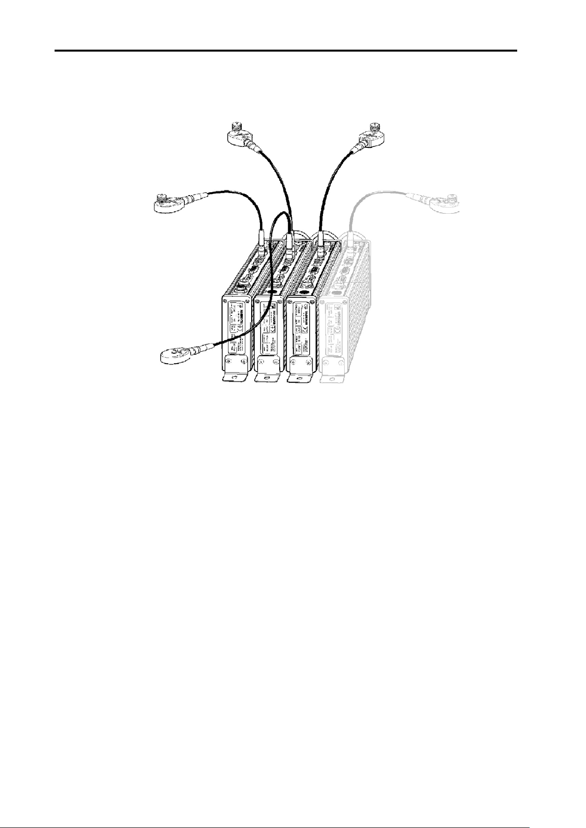
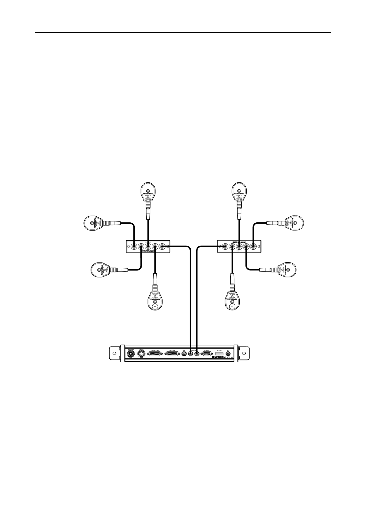
When used as a multi-axis system, the RCU10s are linked via a high-speed serial link;
this allows the RCU10s to share sensor information and operating data.
Figure 1.3 – Multi-axis system
1.3 Compensation functions
The RCU10 is capable of performing a number of processing functions on position
feedback signals. These compensation modes can be enabled or disabled, depending on
the application requirements and type of encoder used. The following section provides an
overview of these modes. Full details can be found in Appendix G.
1.3.1 Scale factor
The RCU10 is capable of performing a fixed scale factor correction to convert the intrinsic
encoder resolution into a more useable value (e.g. 633 nm -> 1 µm). The scale factors
available depend on the input resolution and the type of output required.
This is the basic mode of operation when no compensation functions are enabled.
1.3.2 Air refractive index compensation
Air refractive index (wavelength) compensation is applied according to the environmental
values received from the air temperature and pressure sensors. This mode of
compensation is used with laser encoders to provide a consistent and accurate feedback
signal regardless of current environmental conditions.
Page 16

System overview 1-5
Since the wavelength of light is a function of the ambient conditions local to the beam
path, without compensation errors can incur. This error is of the order of 1 ppm for each
of the following changes in environmental conditions:
1 °C (≈1.8 °F) Change in air temperature
1 ppm for every 3.3 mbar (≈0.1 in/Hg) Change in air pressure
30% RH @ 40 °C Change in relative humidity
Air temperature sensors are provided to monitor any local temperature variation within the
boundaries of the machine. An air pressure sensor is built into the compensator unit
(RCU10-P model only). Humidity is assumed to be relatively constant, and a fixed value
may be entered via the configuration software.
To enable the RCU10 system to perform in real time, each of these sensors is read, and
the related computation (Edlen’s equation*).
* See Appendix G
1.3.3 Encoder thermal expansion compensation
When using conventional scale encoders, the positional accuracy of the system will
depend on the thermal expansion of the scale substrate material. The RCU10 is capable
of compensating for this effect by measuring the temperature of the scale and applying
the relevant positional correction. This will significantly improve system accuracy when
subjected to temperature variation.
To utilise this compensation mode, a material temperature sensor must be placed on the
scale substrate material and the RCU10 configured with the scale’s coefficient of thermal
expansion (CTE) and the distance between the machine home and expansion origin
position.
1.3.4 Workpiece thermal expansion compensation
The system can also perform material thermal expansion compensation. The function of
this feature is to track workpiece temperature and perform compensation based on its
CTE, such that the axis position is modified in real time to produce a part with the correct
dimensions for current environmental conditions.
To utilise this compensation mode, a material temperature sensor must be fitted to either
the part being machined, or a part of equivalent thermal characteristics. A reference
location, from which the workpiece is expected to expand, should be identified (by
consideration of part fixturing method etc). Once workpiece compensation is enabled, the
machine position will be modified to account for workpiece expansion relative to this
reference location.
Page 17
1-6 System overview
New
‘expanded’
size
Reference point,
centre of the
workpiece
Anchor
point
Expanded
size
Expansion is forced in
these directions, away
from the anchor point
Workpiece expansion concept
The size of a workpiece is proportional to its CTE and the ambient temperature. One of
the major sources of error in large parts can be ‘feature misplacement’, which can result
from thermal expansion or contraction of the part.
Consider two matching workpieces – one made at 30 °C (86 °F) and one made at 20 °C
(68 °F). If these parts are machined without workpiece expansion compensation applied,
they will not be the same size when brought together at the same temperature (the part
made at the higher temperature will be smaller than the one made at the lower
temperature).
By constantly monitoring the workpiece temperature, the RCU10 can use its CTE to
calculate the expansion that has occurred relative to a nominal reference temperature of
20 °C (68 °F). This process ensures that parts machined in a poorly controlled
environment will be as accurate and consistent as parts machined in an environment
maintained at 20 °C (68 °F). That is to say, no matter what temperature the part is
machined at, it will be the correct size when measured at 20 °C (68 °F).
Expansion is a greater problem in large workpieces because the amount of expansion is
proportional to the distance from the reference point. For example, at a point 40 m
(≈130 ft) from the reference point on an aluminium workpiece at 30 °C (86 °F), the error
will be 8 mm (5/16 in).
Figure 1.4 – Workpiece expansion
Workpiece compensation reference point
It is up to each user to establish a reference point suitable for their specific workpiece and
application. Some experimentation may need to be carried out in order to determine how
each fixture or workpiece behaves and thus the best way to apply compensation.
The process of defining a reference point can be complex and depends on many factors.
It is up to the user to decide on the best jigging and anchoring options for the workpiece.
Page 18

System overview 1-7
Expansion coefficients
The RCU10 recognises expansion coefficients as parts per million per degree Celsius or
degree Fahrenheit (the unit of temperature used depends on how the user configures the
system). The reference temperature for material expansion is 20 °C (68 °F).
Table 1.1 below shows example expansion coefficients for aluminium and steel:
Table 1.1 – Expansion coefficients
Material ppm/°C ppm/°F
Aluminium 20 11.11
Steel 10 5.56
Use the following formula to convert from ppm/°C to ppm/°F:
[ppm/°C] multiplied by 5/9 = [ppm/°F]
e.g. 20 ppm/°C x 5/9 = 11.11 ppm/°F
1.3.5 Structure thermal compensation
An additional source of positioning error may be the thermal distortion of the machine
structure. This could manifest in a number of ways including:
expansion of the spindle
expansion of the machine structure
As long as the thermal effect is linear and not related to axis position, the RCU10 can be
used to reduce the error.
To utilise this compensation mode, a material temperature sensor must be placed on the
applicable part of the machine structure and the RCU10 configured with the number of
micrometres of correction required per degree C.
Page 19

1-8 System overview
1.4 Operational functions
A number of useful operational functions (some optional) are available on the RCU10 to
provide flexibility and ease of use.
1.4.1 Selectable parameter tables
A number of ‘parameter tables’ are available for use during operation, which are
selectable through external I/O. These allow easy ‘switching’ of a number of common
options/operations, including:
Dead path or reference offset from scale expansion origin
Workpiece temperature sensor
Workpiece expansion coefficient
Workpiece origin offset
Workpiece origin type
The use of these switchable parameters allows numerous functions such as:
Multiple machine home positions
Changing to an alternative machining zone
Use of multiple workpiece material sensors (for multiple machine zones or other
reasons)
Changing of the material type (e.g. aluminium/steel)
1.4.2 Compensation buffering
When the RCU10 is in this mode, it will continue to monitor the encoder input and perform
the relevant quadrature scaling. However, any injection required to maintain compensated
position will be stored in a buffer within the RCU10. When the mode is disabled, any
stored (buffered) count is slowly injected into the motion feedback loop and the fully
compensated position re-established. The rate at which this compensation is injected is
user-configurable.
This function is useful where an axis needs to be temporarily disabled, but the original
position recovered at a later time. For example, some machines have an Emergency Stop
button that can be used to temporarily stop machine operation, but continue after it is
released without having to re-home the machine. In this case the injection compensation
is buffered, preventing any movement during the ‘E-stop’ period which would cause a
following error on the machine controller.
Page 20
System overview 1-9
Powered from 24
digital signal processor based compensation electronics and
an
laser encoder and require refractiv
RCU10
applications, only one RCU10
compensation for additional axes is provided by
RCU10
the pressure senso
the network via a high-speed serial link.
Similar to the RCU10
not contain a pressure sensor.
Note that one RCU10 compensation un
axis to be compensated. For example, a three
encoder based system would need:
and a three
need:
3 off RCU10-XX-XX
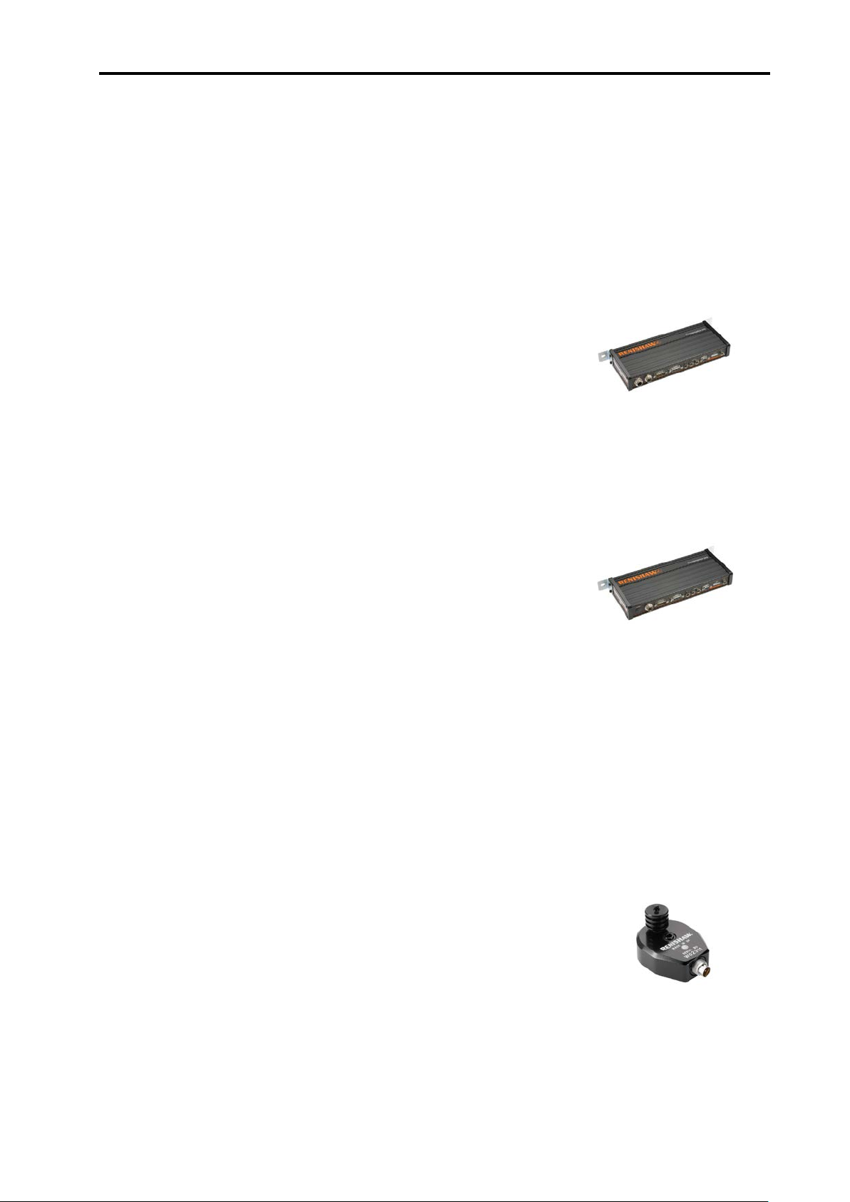
The air temperature sensor is used in applications that
require refractive index compensation. The sensor contains a
calibrated thermistor to monitor ambient air temperature in
the range of 0 °C to 40 °C. The temperature readin
converted into a digital signal inside the sensor, which
reduces susceptibility to noise when the reading is
transmitted to the RCU10.
1.5 System components
The following provides a brief overview of the main system components:
Compensation unit with internal air pressure sensor
(part number: RCU10-PX-XX)
V dc, the RCU10-PX-XX contains the
internal air pressure sensor. For applications that use a
e index compensation, the
-PX-XX unit is a requirement. In multi-axis
-PX-XX is necessary because
-XX-XX units (detailed below). In these applications,
r reading is distributed to other RCU10s in
Compensation unit (part number: RCU10-XX-XX)
-PX-XX, however this assembly does
it is required for each
-axis laser
1 off RCU10-PX-XX
2 off RCU10-XX-XX
-axis tape or glass scale encoder system would
Air temperature sensor (part number: RCU10-AT-XX)
g is
Page 21

1-10 System overview
The material temperature sensor is used in applications
scale, workpiece or machine structure compensation. The sensor
contains a calibrated thermistor to monitor material surface
temperature in the range of 0 °C to 55 °C. The temperature reading is
converted into a digital signal inside the senso
susceptibility to noise when the reading is transmitted to the RCU10.
A five
the RCU10 units, or to the remote sensor distribution
number RCU10
of cable is required, sensor cables can be daisy
cable lengths in 5-metre increments to be configured.
Supplied on a CD
compensation system to meet the requirements of the application.
Communication with the RCU10 units is established through an
RS485 serial link; in some instances this may nec
USB to RS232 converter
and the RCU10 units.
The high
linked as a netwo
set up by connecting the computer system to only one of the RCU10
units. Any information required by remote RCU10 compensators in the
network is automatically distributed across the link to the appropriat
RCU10 compensator when the configuration file is transmitted to the
RCU10s.
Once in operation, the high
as the environmental sensor readings to be shared amongst all
compensators in the network.
This is used to connect a computer serial port to the RCU10
compensation unit.
Laser encoder technical documentation
(part number: A
CD containing pdfs of data sheet
laser encoder product
Material temperature sensor (part number: RCU10-MT-XX)
that require
r, which reduces
Sensor cable (part number: RCU10-TC-X5)
-metre cable that connects sensors directly to the sensor ports on
units (part
-DB-XX). In applications where more than five meters
-chained enabling
RCU CS configuration software (part number: RCU10-CS-XX)
-ROM, this software enables the user to configure the
RS232 or
essitate the use of a
(A-8014-0670) between the computer s ystem
High-speed serial link cable (part number: A-9904-1451)
-speed serial link cable allows a number of RCU10 units to be
rk. During configuration a multi-axis system can be
-speed serial link enables parameters such
PC RS232 cable (part number: A-9904-1456)
-9904-2407)
s and installation guides for
s.
e
Page 22
System overview 1-11
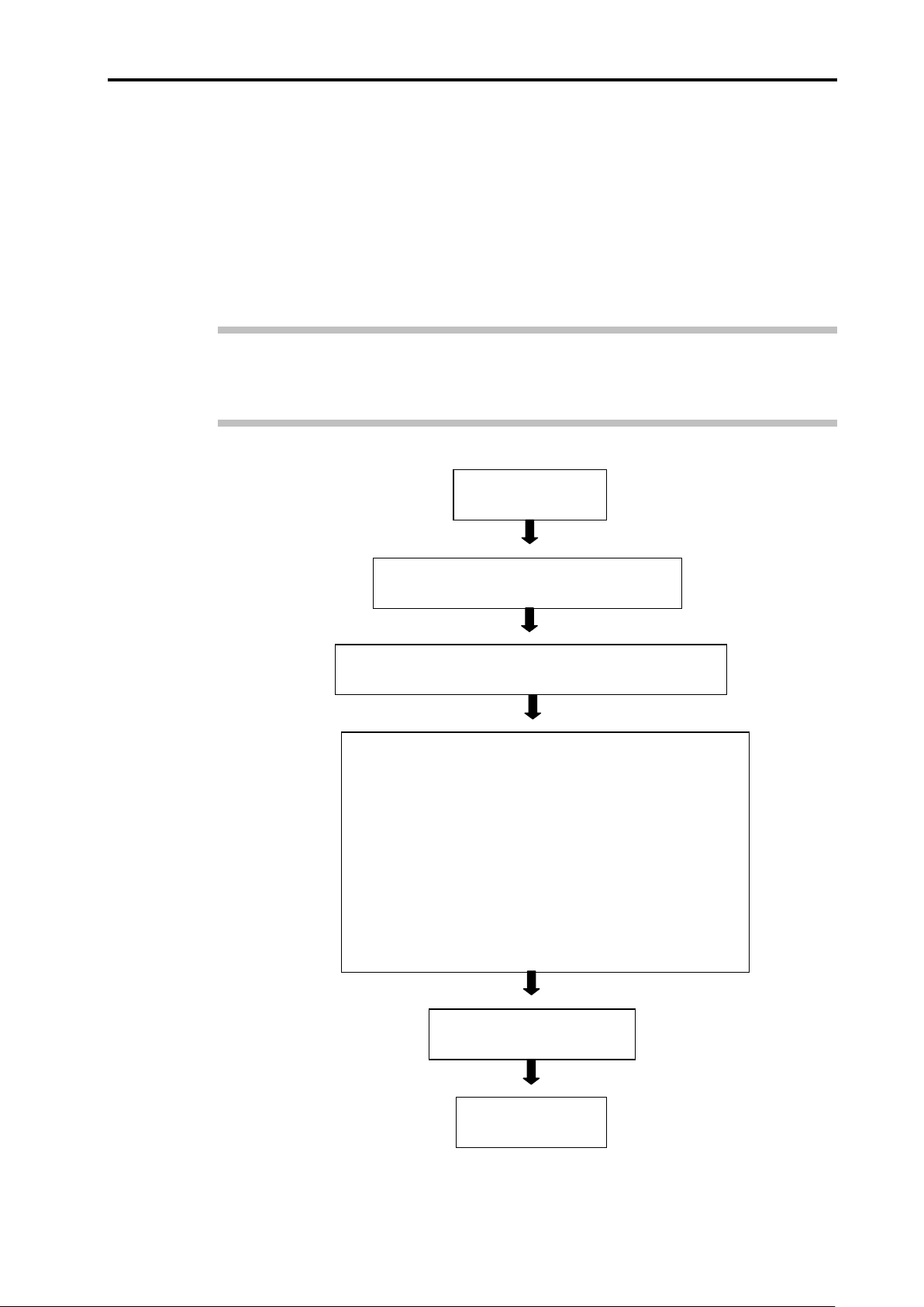
System design
Section 2
Define the required RCU10 kit number
Section 3
Check delivered kit contains all expected components
Section 3
System installation
Section 4
Whilst undertaking this process, the feedback loop to the
machine must not be closed and all motion must be disabled.
The system installation process is split into the following
sections:
•
Hardware installation and initial power-up
•
RCU10 unit address set-up
•
Electrical installation
•
System configuration
•
Configuration validation
Controller integration
Section 5
Operation
Section 6
1.6 Installation procedure overview
Since the RCU10 system may be used in a diverse range of applications, from simple
open-loop calibration systems to complex multi-axis closed loop motion systems, it is
difficult to specify an optimum installation procedure for all cases. However, if sections 2
to 6 of this manual are followed sequentially, as outlined in the procedure below, the user
will be taken through a typical installation process.
Note: The user should be aware that to streamline the installation process, detailed
information has been placed within the appendices. Reference to these appendices is
made where appropriate.
Figure 1.5 – Installation flow diagram
Page 23

1-12 System overview
This page is intentionally left blank.
Page 24

System design 2-1
Section 2
System design
Contained in this section
2.1 Requirements ........................................................................................................ 2-2
2.2 Sensors and sensor networks ............................................................................... 2-3
2.2.1 Environment sensors ................................................................................. 2-3
2.2.2 Sensor network connection ....................................................................... 2-4
2.3 Electrical connections ............................................................................................ 2-5
2.3.1 Connector positions ................................................................................... 2-5
2.3.2 Connector functions .................................................................................. 2-6
J1 – 24 V dc power .................................................................................... 2-6
J2 – Controller output ................................................................................ 2-6
J3 – Encoder input..................................................................................... 2-6
J4 – Reference switch port ........................................................................ 2-7
J7 – Auxiliary I/O ....................................................................................... 2-8
J8 – PC port............................................................................................... 2-9
2.4 Velocity/resolution/bandwidth considerations ........................................................ 2-9
2.4.1 Encoder input frequency .......................................................................... 2-10
2.4.2 Output frequency ..................................................................................... 2-10
2.5 Referencing ......................................................................................................... 2-12
2.5.1 Signal format and re-synchronisation ...................................................... 2-12
2.5.2 Referencing options ................................................................................ 2-14
2.6 RCU10 component mounting .............................................................................. 2-17
2.6.1 RCU10-XX-XX or RCU10-PX-XX ........................................................... 2-
2.6.2 Air temperature sensor ............................................................................ 2-18
2.6.3 Material temperature sensor ................................................................... 2-19
2.6.4 Sensor distribution box ............................................................................ 2-20
17
Page 25

2-2 System design
2.1 Requirements
The RCU10 has been designed for maximum flexibility so that it can suit a wide range of
applications whilst maintaining simple configuration and installation. In order to use the
RCU10 system certain requirements should be met:
24 V dc power source ±2 V with each compensator requiring up to 250 mA. The
power source should have short circuit protection.
An encoder that provides digital quadrature in differential RS422 format at one of
the resolutions defined in Section 2.4.2.
Figure 2.1 – RS422 differential line driver outputs
An axis controller which:
accepts either:
• digital quadrature in differential RS422 format, or
• analogue (Sine/Cosine) quadrature in 1 Vpp format.
is capable of recognising an error condition by one of the following methods:
• RS422 differential error line.
• quadrature disconnection (loss of differential drive of digital inputs,
amplitude drop in analogue input applications).
In the simplest configuration it is possible to use the RCU10 without any input
control lines. However, for basic or extended operation the controller should have
input/output lines working at either 24 V or 5 V logic thresholds.
Basic operation:
• one controller output line (reset)
• one controller input line (error)
Extended operation:
• controller output lines – maximum of six per axis (all RCU10 functions used)
• controller input lines – maximum of three per axis (error, suspend and
warning)
Page 26

System design 2-3
2.2 Sensors and sensor networks
2.2.1 Environment sensors
Two types of remote RCU10 sensor are available – one for sensing air temperature and
one for sensing material temperature. Both sensors have built-in electronics to convert the
temperature reading into RS485 data. Consequently, many sensors can be linked
together to form a network. Furthermore, the signal is digital, making it less susceptible to
electrical noise and allowing it to be transmitted without error over a longer distance.
Each sensor in a system needs a unique address for the network to work correctly. The
RCU10 sensors are factory-programmed with an address that is the same as the serial
number of the sensor (engraved on the sensor body).
Each sensor port can supply power to a maximum of four sensors, which means a total of
eight connected to any single RCU10 axis.
The sensors for a particular axis do not have to physically plug into the related axis's
RCU10; sensors may plug into any RCU10. The configuration software allows the user to
assign any sensor data to any RCU10 within the system.
The sensors may be connected using the standard pre-made cables available in 5 m
lengths from Renishaw. Alternatively, custom cables may be made by the user (connector
kits are available). Please see Appendix B for standard and custom cable specifications.
Figure 2.2 – Air temperature and material temperature sensors
Page 27
2-4 System design
2.2.2 Sensor network connection
Two sensor network ports (J5 and J6 – see Figure 2.4) are provided per RCU10, to which
all the air temperature and material temperature sensors are connected. Up to four
sensors may be connected to each RCU10 sensor port using the sensor distribution box
(as shown in Figure 2.3), making a maximum of eight sensors per RCU10. There is a limit
of 32 sensors per multi axis system.
Additionally, of these 32 sensors, only 24 may be distributed. Distributed sensors are
those configured to be used by RCU10s other than the RCU (or RLU) to which they are
directly connected. This may be necessary when a sensor is to be used by more than one
axis, or where connection to a different RCU10 is more convenient than connection to the
one that will use it.
Figure 2.3 – Sensor distribution
Page 28
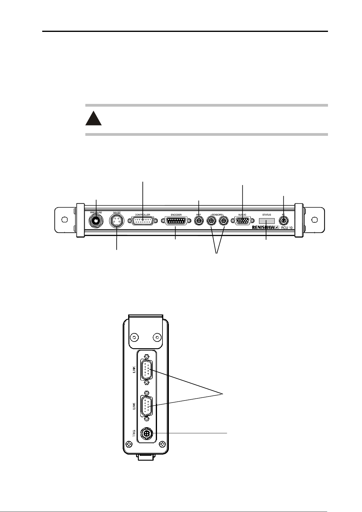
System design 2-5
Not currently used
Pressure sensor
(optional)
J1 – 24 V dc power
J2 – Controller output
J3 – Encoder input
J4 – Reference switch port
J5 and J6 – Sensor network ports
J7 – Auxiliary I/O
Status display
J8 – PC port
!
High-speed serial
2.3 Electrical connections
The following pages provide details of the RCU10 input and output ports and the signal
functions and types. For information on the connectors and hardware installation details
refer to Appendix B.
CAUTION: Do not connect anything other than Renishaw environmental sensors
to the sensor ports.
2.3.1 Connector posit ions
Figure 2.4 – Front panel layout
communication link
Figure 2.5 – Top panel layout
Page 29

2-6 System design
!
2.3.2 Connector funct ions
J1 – 24 V dc power
The RCU10 uses 24 V dc as its power supply. Power supply requirements can be found in
Appendix A. If required, a power supply with a remote sense function can be used. For
connector pinout and hardware installation details please refer to Appendix B.
Note: When using a network of RCU10s the 24 V supply should be applied
simultaneously for all units.
CAUTION: The correct power supply voltage is 24 V ± 2 V. Power supplies
outside this range may give unreliable operation.
J2 – Controller output
The controller output connector provides the position feedback signals that pass to the
machine control or counter. These comprise digital A quad B (or analogue sinusoidal)
encoder signals, reference Z pulse and error signals.
The RCU10 can be configured to provide output position data to the machine controller in
either digital incremental A quad B (RS422 differential line driver output) or analogue
incremental sine/cosine format (1 Vpp differential sine and cosine line driver outputs)
using the configuration software. The output resolution of the RCU10 system may be
selected from a number of available options, depending on the encoder input resolution
and output format required.
Renishaw supplies connector kits to assist users in the construction of suitable cables –
please refer to Appendix B for connector pinout and hardware installation details.
J3 – Encoder input
The RCU10 has been designed to accept digital quadrature from three main types of
encoder:
Renishaw RLE10 laser encoder
Renishaw HS10 laser encoder
Generic tape/glass scale
The encoder type is selected through the configuration software, and the encoder input
port must be wired to suit the selected type. Renishaw supplies connector kits to assist
users in the construction of suitable cables – please refer to Appendix B for connector
pinout and hardware installation details.
The tables in section 2.4.2 show the available RCU10 output resolutions for a given
encoder type and input resolution – along with the maximum velocities, as discussed in
section 2.4.
Page 30
System design 2-7
RCU10
100 mA MAX
+
5 V
4
3
5 V
driver
High
side
0 V
Low
side
Switch
5 V
0 V
2
1
!
WARNING: To ensure that the motion control system receives quadrature of the
expected resolution and frequency, it is important to set both the input and output
resolutions of the Renishaw system correctly. If the quadrature resolution is set
incorrectly, the axis may move for distances and at speeds that are not expected. For
example, if the output resolution of the RCU10 system is set to double that of the
controller input, the axis may move twice as far and twice as fast as expected.
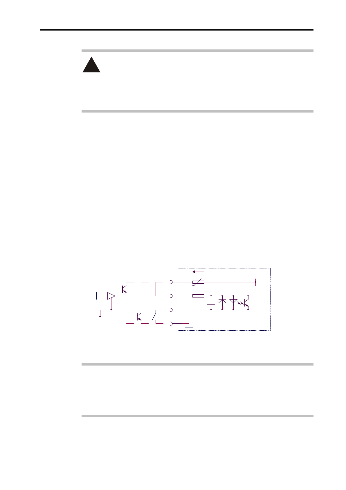
J4 – Reference switch port
The reference mark input may be used to receive a reference position marker pulse. Two
options are available when configuring the RCU10: either a reference mark derived from
the encoder (through the encoder where Z and /Z are the reference mark input lines), or
connected to the REF input. The REF input can accept a range of actuator types that
have solid state (high side or low side), 5 V logic signal or mechanical switch output
formats.
The reference process is triggered by the current’s rising edge on switch closure. The
reference signal must last for at least one input encoder pulse transition and, once the
process has been started, another cannot be activated for a period of 1 second. Providing
this is adhered to, no restriction is placed on axis velocity during referencing, except for
the repeatability caused by the time delay introduced by the interface circuit. Please refer
to Appendix B for connector pinout and hardware installation details and section 2.5 for
signal and phasing information.
Figure 2.6 – Reference mark actuator connection
Notes: TTL driver signals are not suitable for use here. The thresholds are 3 V high
and 1 V low.
The reference mark signal will only function in conjunction with quadrature, ie
not stationary.
Page 31

2-8 System design
J7 – Auxiliary I/O
The auxiliary input/output connector provides various functions that can be used to control
and monitor the operation of the RCU10. These functions are described below.
Table 2.1 – J7 pinouts (Auxilia ry I/O)
Pin Auxiliary
I/O function
1, 11
12, 13
3
4
7 PULL -
5 /Seek reference I Enables search for reference mark input. LOW
15 /Reset I
14
5 V and 24 V
outputs
Parameter table
select 1 and 2
/Workpiece
compensation
enable
/Workpiece
compensation
temperature freeze
/Compensation
buffering enable
I/O Active
O
I
I Enables workpiece compensation. LOW
I
I Enables the compensation buffering function. LOW
5 V and 24 V outputs @ 100 mA max.
Link to PULL for voltage selection.
Used to select active parameter table.
(Refer to parameter table operation in Appendix F).
Freezes the value of the workpiece temperature at
the current value when activated.
All I/O is weakly pulled to the voltage set of this
terminal i.e. 5 V or 24 V.
Connect to 5 V (1) or 24 V (11) as required.
Note: This must also be selected to match the
RCU10 configuration.
Resets the RCU10 output error latch and HS10
laser (if used). Reset signal must be held active for
a minimum of 100 ms to ensure correct operation.
-
-
LOW
-
LOW
6 /Error (24 V) O
9 /Suspend O LOW
10 /Warning O LOW
The port can be configured to work with either 5 V or 24 V logic I/O by connecting the
PULL input, within the auxiliary I/O connector, to either 5 V (pin 1) or 24 V (pin 11)
respectively. Also ensure that the relevant threshold is selected in the Controller Logic
parameter in the system configuration (see section 4.2.3 for details). Please refer to
Appendix B for connector pinout and hardware installation details.
Outputs that may be used as an advanced option to
determine the state of the RCU10 (see below).
LOW
Page 32

System design 2-9
J8 – PC port
The PC port is used to connect the RCU10 to the RS232 port of a computer. Once
connected, the PC may be used with the Renishaw RCU CS software to both configure
the RCU10 and monitor the RCU10 during operation.
The PC port may be used with either a standard RS232 interface or an RS485 interface.
The RS485 format is used when long distances are required between the RCU10 and the
PC or, in situations where a high level of electrical noise is expected. Connection should
be made to either the RS232 or
The PC may be connected using the standard pre-made RS232 cable available in a 1 m
length from Renishaw. Alternatively, custom cables may be made by the user (connector
kits are available). Please see Appendix B for connector pinouts and standard cable
specifications.
Notes: New PCs are increasingly being supplied with no RS232 ports (ie USB ports
only). Because of the interface problems this presents, Renishaw supplies a
serial-USB adaptor (see section 3.3 for ordering details).
RS485 as required, but not to both simultaneously.
On multi-axis systems only one PC must be connected.
2.4 Velocity/resolution/bandwidth considerations
One of the key considerations in configuring an encoder feedback system is to ensure
that certain frequency dependent parameters are configured correctly.
These parameters are:
Encoder resolution
Maximum required axis velocity
RCU10 input sample rate
RCU10 output resolution
RCU10 output update rate
Controller sample rate
The logical sequence for determining these parameters is as follows:
Page 33

2-10 System design
2.4.1 Encoder input frequency
Determine the encoder resolution.
Determine the maximum required axis velocity (see Tables 2.2 to 2.5 to determine
the maximum velocity for different resolutions and encoders).
Calculate the maximum encoder (edge-to-edge) frequency as follows:
Encoder frequency (MHz) = Velocity (m/s)
Ensure that the encoder frequency is less than 20 MHz and less than the RCU10
sample rate setting.
Note: The input sample rate of the RCU should be at least 25% greater than the encoder
output quadrature rate.
Encoder resolution (µm)
2.4.2 Output frequenc y
Determine the RCU10 output (controller input) resolution.
Calculate the maximum output frequency as follows:
Output frequency (MHz) = Velocity (m/s)
Output resolution (µm)
Ensure that the RCU10 output update rate is at least 5% greater than the output
frequency.
Ensure that the controller sample rate is greater than the RCU10 update rate
setting.
In the case where analogue (Sine/Cos) output signals are being used from the RCU10,
the frequency of the sinusoids can also be calculated as shown above.
Note: The customer’s controller must have an input bandwidth which is at least 25%
greater than the output quadrature rate of the RCU.
Page 34

System design 2-11
Table 2.2 – Maximum velocity for digital output resol u tions - RLE10 or HS10 laser encoder
Encoder input
resolution
(nm)
633 5.000 m/s
316 5.000 m/s 5.000 m/s
158 3.164 m/s 3.164 m/s
79.1 1.582 m/s 1.582 m/s
39.6 * 0.791 m/s 0.791 m/s
19.8 * 0.396 m/s 0.396 m/s
9.9 * 0.197 m/s 0.197 m/s 0.197 m/s
* only available from RLE10
Table 2.3 – Maximum velocity for analogue output resolutions - RLE10 or HS10 laser encoder
Encoder input
resolution (nm)
316 5.00 m/s
158 3.164 m/s 3.164 m/s 3.164 m/s
0.01 0.02 0.05 0.1 0.5 1 5
20 25 40 50 100
RCU10 output resolution (digital (µm))
RCU10 output resolution (sinusoid period (µm))
79.1 1.582 m/s 1.582 m/s 1.582 m/s 1.582 m/s
39.6 * 0.791 m/s 0.791 m/s
* only available from RLE10
Table 2.4 – Maximum velocity for digital output resol utions - tape/glass scale encoder
Encoder input
resolution (µm)
0.1 2.000 m/s 2.000 m/s 2.000 m/s
0.5 5.000 m/s 5.000 m/s 5.000 m/s
1 5.000 m/s 5.000 m/s
5 5.000 m/s
Table 2.5 – Maximum velocity for analogue output resol utions - tape/glass scale encoder
Encoder input
resolution (µm)
0.1 2.000 m/s 2.000 m/s 2.000 m/s
0.1 0.5 1 5
RCU10 output resolution (digital (µm))
RCU10 output resolution (sinusoid period (µm))
40 50 100
Page 35

2-12 System design
A quad
Bquad
Reference Input
Reference Output
5 Output Counts
FORWARD
2.5 Referencing
2.5.1 Signal format and re-synchronisation
When using a laser encoder, the exact phasing of the reference signal relative to the sine
and cosine signals cannot normally be guaranteed, because the position of the interfering
light waves is not mechanically registered relative to the position of the reference switch.
To overcome this, the RCU10 includes a circuit that re-phases the position signals so that
the reference mark output occurs synchronised and in a repeatable position.
Digital interface re-synchronisation
The output is produced when A is high and B is high. The re-synchronisation process
ensures a reference output will occur at 5 ±1 output quadrature counts later than the
reference input.
Figure 2.7 – Digital interface re-synchronisation
Page 36

System design 2-13
Cosine
Sine
Reference In
REFERENCE Valid
320 Output Counts
Reference Out
FORWARD
256 Output Counts
Analogue interface re-synchronisation
The output is produced between –45° and +135° and is valid when the amplitude of sine
and cosine are equal. The re-synchronisation process ensures a reference output starts
nominally 256 output counts later than the reference input and is valid at 320 ±1.
Figure 2-8 – Analogue interface re-synchronisation
Page 37

2-14 System design
2.5.2 Referenci ng options
Axis referencing with minimum control inputs
In the simplest configuration it is possible to use the RCU10 without any input control lines
by linking ‘Seek Reference’ and ‘Reset’ to 0 V.
When ‘Seek Reference’ is linked permanently to 0 V, the reference mark input will be
permanently active, and every time the machine passes over the reference actuator an
output reference mark will be issued. In this case it is advisable that the reference position
is located outside the normal working zone of the axis.
Linking ‘Reset’ permanently to 0 V will cause the RCU10 to automatically reset the error
output state when the cause of the error has ceased. For momentary error conditions, the
output will be active for at least 100 ms.
Figures 2.9 and 2.10 show the sequence for referencing the axis with laser and non-laser
encoders respectively with both 'Seek Reference’ and ‘Reset’ linked to 0 V.
Figure 2.9 – Simple mode axis referencing sequence with laser encoder input and
Seek reference and Reset inputs to RCU10 tied to 0 V
Page 38

System design 2-15
Figure 2.10 – Simple mode axis referencing sequence with non-laser encoder input
and Seek reference and Reset inputs to RCU10 tied to 0 V
Axis referencing with ‘Seek reference' and ‘Reset’ provided by the motion controller
In applications where it is not possible to locate the reference position outside the working
zone, the ‘Seek Reference’ line can be used to enable a reference cycle. In this mode of
operation, taking the ‘Seek Reference’ line low enables the reference mark input line into
the RCU10. At all other times (i.e with ‘Seek Reference’ high) the reference mark request
is ignored.
Figures 2.11 and 2.12 show the axis referencing sequence for laser and non-laser
encoders respectively with when both ‘Seek Reference’ and ‘Reset’ signals are provided
by the machine controller.
Note that following a power-up of the compensation system, it is recommended that a
‘Reset’ be applied as shown in Figures 2.11 and 2.12.
Page 39

2-16 System design
Page 40

System design 2-17
350 (13.78)
325 (12.8)
293 (11.54)
133.5
42 (1.65)
Mounting holes
Dimensions in
mm (in)
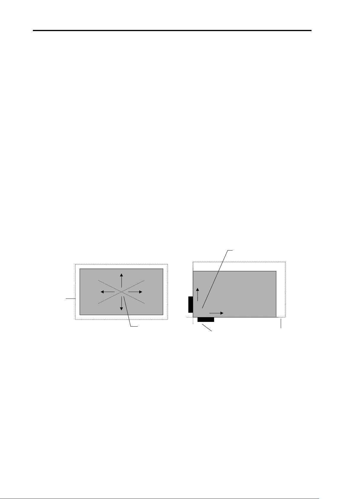
2.6 RCU10 component mounting
2.6.1 RCU10-XX-XX or RCU10-PX-XX
The RCU10 is intended to be mounted in an electrical control cabinet or similar
environment. It is constructed with IP40 protection and therefore needs to be protected
from harsh environmental conditions.
The RCU10 may be mounted in any orientation, although the status display window is
intended to be read with the unit vertical (display window to the top).
If the RCU10-P is to be contained in a sealed enclosure, it will be necessary to port the
pressure sensor aperture to the outside environment such that the correct air pressure is
measured. This can be done by using 4 mm O.D. plastic tubing which will simply push fit
into the aperture. To remove the plastic tube, push the collet towards the connector whilst
pulling the tube.
Figure 2.13 – RCU10 dimensions
7 mm x 9.5 mm
(5.26)
For connector/cable clearance purposes, allow 100 mm (4 in) from the front face of the
RCU10. Additionally, if a multi-axis system is being installed, allow 100 mm (4 in) from the
top face of the unit for the high-speed serial link cables.
Note: Using the fixings supplied with the unit (M4 x 5 cap head screws + 4 mm plain
washers) ensures that earthing is achieved directly through the brackets.
Page 41

2-18 System design
∅ 3.5 (0.13)
16 (0.63)
36 (1.42)
34 (1.34)
25 (0.98)
46 (1.81)
90 (3.5) min
75 (2.95) min
Standard cable
Armoured cable
Dimensions in mm (in)
2.6.2 Air temperature sensor
RCU10-AT-XX
The air temperature sensor may be mounted either by the built-in magnetic base or using
the central mounting hole. It is recommended for permanent installations that the
mounting hole be used for security.
The sensor should be positioned in a dry location in air next to the laser beam. An
armoured cable option is available for applications where there is a danger of the cable
being stressed or cut.
The sensor is show below with both the standard and armoured cable options, with
minimum clearance dimensions indicated.
Figure 2.14 – Air temperature sensor dimensions
Page 42

System design 2-19
16 (0.63)
36 (1.42)
17 (0.67)
∅3.5 (0.13)
25 (0.98)
46 (1.81)
90 (3.5)
75 (2.95) min
Standard cable
Armoured cable
Dimensions in
mm (in)
2.6.3 Material temperature sensor
RCU10-MT-XX
The material temperature sensor may be mounted in a similar way to the air temperature
sensor, by using either the built-in magnetic base or the central mounting hole. It is
recommended for permanent installations that the mounting hole be used for security.
The material sensors have IP67 protection and therefore can be placed in positions that
may have liquid or particle contamination. It is common for material temperature sensors
to be mounted in variable locations on a machine area, being removed and replaced as
required. An armoured cable option is available for applications where there is a danger of
the cable being stressed or cut.
Figure 2.15 – Material temperature sensor dimensions
Note: For maximum accuracy it is important to maintain good thermal contact between
the base of the sensor and the material being measured. Thermally conductive grease/oil
or paste may be beneficial.
Page 43

2-20 System design
110 (4.33)
17 (0.67)
∅ 3.5 (0.14) C’BORE ∅ 6 (0.24) x 3 (0.12)
100 (3.94)
8.5 (0.35)
5 (0.2)
30 (1.18)
2.6.4 Sensor distribution box
RCU10-DB-XX
The sensor distribution box allows up to four sensors to be connected to a single RCU10
sensor port. One cable is attached to the RCU10 and the sensors are plugged into the
distribution box at a remote location.
The box may be mounted vertically or horizontally, using either set of holes.
Figure 2.16 – Sensor distribution box dimensions
Page 44

Kit configuration and part identification 3-1
Section 3
Kit configuration and part identification
Contained in this section
3.1 Defining kit numbers .............................................................................................. 3-2
3.2 Kit numbers and part identification ........................................................................ 3-3
3.2.1 RCU10 kit numbers (laser encoder based systems) ................................. 3-3
3.2.2 RCU10 kit numbers (non-laser encoder based systems) ......................... 3-4
3.3 Additional components and part identification ....................................................... 3-5
Page 45

3-2 Kit configuration and part identification
3.1 Defining kit numbers
To simplify the ordering process, complete systems can be identified through one kit part
number. The format of this kit part number is shown below, along with tables that identify
the contents.
Kits for laser compensation applications include one RCU10-P, whilst kits for non-laser
applications include only the RCU10 version.
Any of the parts may be ordered separately if required.
N - Total number of axes in system
Range: 1 – 6
N - Number of air sensors required
Range: 0 – 6
It is assumed that, if an air sensor is required, at least
one axis will be using refractive index compensation.
Therefore one of the RCU10s provided will be an
RCU10-PX-XX which contains a pressure sensor.
RCU10-NNAAA
Figure 3.1 – RCU10 kit part numbers
A - Number of material sensors
Range: Z=0, A=1, B=2 etc (maximum = 25)
A - Number of standard 5 m sensor cables
Range: Z=0, A=1, B=2 etc (maximum = 25)
A - Number of sensor connector kits
Range: Z=0, A=1, B=2 etc (maximum = 25)
These are required if the user wants to make their own
sensor cables.
Page 46

Kit configuration and part identification 3-3
11ABZ
22ACZ
33ADZ
44AEZ
55AFZ
66AGZ
3.2 Kit numbers and part identification
The following tables depict standard kits both for systems which use laser encoders and
also those that are non-laser encoder based.
3.2.1 RCU10 kit numbers (laser encoder based systems)
Part number
RCU10-PX-XX
RCU10-XX-XX
RCU10-AT-XX Air temperature sensor
RCU10-MT-XX
RCU10-TC-X5 Sensor cable
Component
description
RCU10 compensation
unit with pressure
sensor
RCU10 compensation
unit
Material temperature
sensor
RCU10-
RCU10-
RCU10-
RCU10-
RCU10-
RCU10-
1 1 1 1 1 1
0 1 2 3 4 5
1 2 3 4 5 6
1 1 1 1 1 1
2 3 4 5 6 7
RCU10-CS-XX RCU10 CS software
A-9904-1455 RCU10 connector kit
A-9904-1636 Sensor connector kit
A-9904-1451 High speed serial link
A-9904-1456 PC RS232 cable
Laser encoder
A-9904-2407
technical
documentation
1 1 1 1 1 1
1 2 3 4 5 6
0 0 0 0 0 0
0 1 2 3 4 5
1 1 1 1 1 1
1 1 1 1 1 1
Page 47

3-4 Kit configuration and part identification
10AAZ
30AAZ
50AAZ
3.2.2 RCU10 kit numbers (non-laser encoder based systems)
Part number
RCU10-XX-XX
RCU10-MT-XX
RCU10-TC-X5 Sensor cable
RCU10-CS-XX RCU10 CS software
Component
description
RCU10
compensation unit
Material
temperature sensor
RCU10-
1 2 3 4 5 6
1 1 1 1 1 1
1 1 1 1 1 1
1 1 1 1 1 1
20AAZ
RCU10-
RCU10-
40AAZ
RCU10-
RCU10-
60AAZ
RCU10-
A-9904-1455
A-9904-1636
A-9904-1451
A-9904-1456 PC RS232 cable
A-9904-2407
RCU10 connector
kit
Sensor connector
kit
High speed serial
link
Laser encoder
technical
documentation
1 2 3 4 5 6
0 0 0 0 0 0
0 1 2 3 4 5
1 1 1 1 1 1
1 1 1 1 1 1
Page 48

Kit configuration and part identification 3-5
3.3 Additional components and part identification
Part number Component description
A-8014-0670 Serial-USB adaptor
RCU10-DB-XX Sensor distribution box
RCU10-AC-X5 Armoured sensor cable (5 m)
Page 49

3-6 Kit configuration and part identification
This page is intentionally left blank.
Page 50

System installation 4-1
Section 4
System installation
4.1 System installation ................................................................................................. 4-2
4.1.1 Hardware installation and initial power-up ................................................ 4-2
4.1.2 RCU10 address set-up .............................................................................. 4-2
4.1.3 Electrical install a ti on .................................................................................. 4-4
4.1.4 RCU CS settings ....................................................................................... 4-4
4.2 System configuration ............................................................................................. 4-5
4.2.1 System configuration ................................................................................. 4-6
4.2.2 Sensor network configuration .................................................................... 4-7
4.2.3 Compensation settings configuration ........................................................ 4-8
4.2.4 Parameter settings configuration ............................................................ 4-13
4.2.5 Transmitting the configuration ................................................................. 4-15
4.3 Configuration validation ....................................................................................... 4-16
Page 51

4-2 System installation
4.1 System installation
Configuring an RCU10 system is a sequential process that requires careful preparation.
Following sections 4.1, 4.2 and 4.3 should take you through the installation and
configuration process. Configuration is carried out using the RCU10 configuration
software (RCU CS).
The process of configuring an RCU10 system involves entering a certain amount of data
– in the case of multi-axis systems, or those using multiple parameter tables, the amount
of data can be quite large. To simplify this process, and to ensure errors are avoided, a
set of sheets to record both the information required to configure an RCU10 system and
the progress through the installation process is included in Appendix H.
4.1.1 Hardware installation and initial power-up
Install the RCU10 units and environmental sensors into your machine, taking into
consideration the mounting requirements detailed in section 2.
At this stage the high-speed serial link cables and controller output cables should
be disconnected
The remaining cables (J3 – Encoder input, J4 – Reference switch port, J5 and J6 –
Sensor network ports and J7 – Auxiliary I/O) are not critical at this stage, and may
be connected now or when configuration is complete.
Apply 24 V power to all RCU10s.
.
4.1.2 RCU10 address set-up
In order for the RCU10s to operate as part of a network, each unit must have a unique
address. All RCU10s are shipped from the factory with a default address of 1.
NOTE: This operation must be carried out on every RCU10 to be used in a network
before connecting the high-speed serial link cables.
Install the RCU CS software onto a suitable PC — for an overview of this software,
including PC requirements and installation instructions, please refer to Appendix C.
The screen layout for the RCU CS is shown in Figure 4.1. Note the menus, buttons
and status bar because they will be referred to throughout the rest of this section.
For a more detailed description of the menus, buttons and status bar please refer to
Appendix C.
Page 52

System installation 4-3
Button bar
Menu bar
Status bar
Serial
status
RCU10
status
Current
Current
level
port
connection
RCU CS
access
operating
mode
Figure 4.1 – RCU10 status display
Connect the PC to the RCU10 that is to be configured, using the PC cable provided.
Click the Receive button on the RCU CS screen. The connected RCU10 unit
should be detected with a default address of 1.
Select the Compensator Address function from the Configure menu. A
confirmation dialogue will appear, displaying the current RCU10 address setting.
Select Yes to change the addres s .
Enter the new system address in the window displayed. The addresses can be in
the range 1 to 6.
NOTE: Each unit must have a unique address before connec ti on as part of a network , for
example a six-axis system must have RCU10s addressed as 1, 2, 3, 4, 5 and 6. It is
important to ensure that compensators are numbered sequentially. They may be
connected in any order, however the physical end units must be identified in the software
for correct termination.
Once you have acknowledged the new address, the RCU CS will reset the RCU10
and re-establish communications. The connected RCU10 will now register with its
new address.
Repeat this process of setting network addresses for all RCU10 units in the system.
Page 53

4-4 S ystem installation
4.1.3 Electrical installation
Once all the RCU10 units have been set to unique addresses, a network may be
established:
Remove power from all RCU10s.
Connect the high-speed serial link cables across the link connectors on the end of
the RCU10s (either link connector may be used because they are part of a common
serial bus).
If your system was supplied with external high-speed link terminators, connect
these into the spare sockets on the RCU10s at either end of the system.
Connect the sensor cables, noting the sensor and the RCU10 that it is connected to
(see Appendix H for information sheets).
Re-apply power to all RCU10s simultaneously (RCU10s in a network must be
powered simultaneously in order to allow them to connect to each other correctly).
Ensure the configuration PC is connected to an RCU10 unit; it may be connected to
any RCU10 in a multi-axis system.
Press the Receive button on the RCU CS screen to establish communications.
The RCU connection wizard screen will appear. Check that all the expected
RCU10s are detected and that all units are in configuration mode before selecting
OK to proceed.
4.1.4 RCU CS settin gs
A number of options may be set using the RCU CS before proceeding with configuration:
System time
The real-time clocks on the RCU10s may be set to the current PC time.
Note: Ensure that the PC time is correct before using this option.
Select Set System Time from the Tools menu.
A message box will display the time that has been set in the real-time clocks for all
the connected RCU10s. This time will be set the next time the system is reset by a
mode change, transmission of configuration data or by selecting Re-boot RCU from
the Tools menu (see Appendix F.2.1.6 for more details).
Page 54

System installation 4-5
Note the
RCU CS display units
The user may select the display units used by RCU CS. These settings are purely for
display purposes on the RCU CS software and do not affect operation.
Select Configure Units from the Tools menu.
Air pressure units may be either Millibars or Inches of Mercury.
Temperature units may be either Celsius or Fahrenheit.
Distance units may be either Metric or Imperial (when using imperial distance
measurements, values are entered and displayed in decimal format). Three options
are available: Inches, Millimetres or Metres.
4.2 System configuration
pressure
sensor and
RCU10
address
before leaving
this screen,
for example
75L324 and
RCU10
address 1
Press the Configuration button in the button bar. The following window will appear:
Figure 4.2 – Configuration window (System tab)
Each of the four tabs: System, Sensors, Compensation and Parameters, must be
configured in turn. The following sections take you through this process.
Page 55

4-6 S ystem installation
4.2.1 System configuration
Select the System tab of the system configuration window.
Configure each setting on the System tab according to the descriptions shown
below.
Make a note of the pressure sensor serial number and the RCU10 address that it is
connected to before completing the configuration on this page.
When complete, press Validate Current Tab to ensure that there are no errors.
NOTE: Pressing Cancel at any time will cause all changes made by the user to be lost.
Pressing OK will check the entire configuration for validity before storing it into the
computer's memory.
Machine Description: May be used to identify the machine to which the RCU10 system
is installed (text field).
Axis Name: A unique identifier of up to two characters for each axis (e.g. X1).
Axis Length: The length of the axis (in scale encoder applications the RCU10
checks that the axis position has not exceeded the total length
specified – compensation is not applied to any extra length).
Error Monitoring: Error Line Only – standard error mode in which the RCU10
produces an ‘Error’ output for any system error.
Error, Suspend and Warning Lines – extended error mode in
which the RCU10 produces a three level error output
(Error/Suspend/ Warning) depending on priority (see Appendix
F.1.2 for further details).
Configure Enables storage of system events/errors for diagnostic
Error Logging: purposes. It is recommended that this is left at the default setting.
Parameter Tables: Single – a single (fixed) set of configuration parameters is
available for each RCU10.
Multiple – up to four (user I/O – switchable) parameter tables are
available for each RCU10. This is selectable from the drop-down
list. Refer to section F.1.5 for details.
E-Stop: Enables the compensation buffering enable line on the J7 –
Auxiliary I/O connector. This puts the RCU10 into a state where
position is monitored and the relevant quadrature pitch
conversion is performed, but any required injection (due to
environmental changes) is stored in a buffer. On disabling this
line, any stored compensation is introduced into the feedback
path to re-establish position.
Page 56

System installation 4-7
4.2.2 Sensor network configuration
All sensors that are to be used in a multi-axis RCU10 system must be identified before
they can be assigned to any functions. The serial number of the sensor is used as a
unique identifier on the sensor network.
Select the Sensors tab of the system configuration window:
Pressure sensor
Air temperature sensor
Material temperature sensor
Laser head (HS20 only)
Add all system sensors ensuring that the Serial Numbers, Sensor Types and the
Connected RCU Addresses (RCU10 to which the sensor is physically connected)
are entered correctly. The connected RCU address is taken from a drop-down lis t
that displays all possible RCU10s in the network. In this menu Other refers to any
unconnected RCU10 units.
On this screen the Error/Warning boundaries for the environmental sensors can
also be configured – these are a set of global limits that may be used as alarms to
indicate that an abnormal environmental condition has occurred. The system
configurator has the option to apply limits to the air and material temperature sensor
readings: minimum, maximum and also the rate of change. If the limits are
exceeded, an error/warning is asserted which can halt operations until either the
temperature settles within the defined range or the rate of change slows to a level
within the set limit.
NOTES: 1. RCU10 Error/warning boundary settings are independent from the
sensor’s internal range and rate of change settings. Consequently, two
different types of errors may be asserted. These are described in
Appendix D.
2. Pressure sensor settings are not user-configurable and are set by the
RCU CS on transmission of the configuration.
When complete, press Validate Current Tab to ensure that there are no errors
before proceeding.
The laser head functionality is provided as a signal strength feedback from the
HS20 laser head when it is connected to the sensor network. This provides the
user with a visual signal strength indication on the RCU-CS sensors window.
NOTE: Pressing Cancel at any time will cause all changes made by the user to be lost.
Pressing OK will check the entire configuration for validity before storing it into the
computer's memory.
Page 57

4-8 S ystem installation
A completed sensor configuration should look similar to that shown in the screen below:
Figure 4.3 – Completed configuration window (Sensors tab)
4.2.3 Compensation settings configuration
At this stage each axis must be configured to specify encoder input settings,
compensation settings, encoder output settings, safety limits and other axis-specific
functions.
Select the Compensation tab from the system configuration window.
Configuration is split into five main sections: Encoder Input, Compensation, Output To
Controller, Limits and Misc. It is recommended that you follow this order during
configuration.
Configure each setting according to the descriptions shown on the following pages.
When all axes are configured, ensure that Inhibit Compensation Mode is
deselected
until the axis configuration has been checked through.
When each axis is complete, press Validate Current Tab to ensure that there are
no errors before proceeding to the next axis.
to allow the system to enter compensation mode. Do not deselect this
Page 58

System installation 4-9
NOTES: For this screen there are sub-tabs for each axis in the system. Each of these
sub-tabs must be configured individually before moving on to the Parameters
tab. Pressing Cancel at any time will cause all changes made by the user to
be lost. Pressing OK will check the entire configuration for validity before
storing it into the computer's memory.
If a cell turns RED, this is because the setting is invalid or unavailable. Hover
the mouse pointer over the cell to determine the cause of the error.
Figure 4.4 – Configuration window (Compensation tab)
Encoder Input
Encoder Type: Selects the type of encoder used from a pre-defined list: RLE
Axis 1, RLE Axis 2, HS10 or Linear Tape and Glass.
Wavelength/Pitch Each encoder type has a different wavelength. This option
displays the wavelength characteristics of a specific type in
micrometres.
Resolution: Selects the resolution (electrical edge-to-edge separation) of
the encoder. Only valid resolutions for the type of encoder
selected will be displayed. See configuration warning 1 on
page 4-12.
Direction sense (input): Sets the input quadrature direction. This must be selected
such that the RCU10 input counts in the same direction as
the machine control. See configuratio n war ning 2 on
page 4-12.
Page 59

4-10 System i nstallation
Sample Rate: Selects the rate at which the RCU10 samples the quadrature
Reference Mark Selects the source for the reference mark signal between:
source:
External Port – uses the RCU10’s J4 – reference switch port.
Compensation
These settings are used to select which modes of compensation are enabled on the
RCU10 hardware.
Air Refractive Index: Selects the air refractive index compensation algorithm
signal from the encoder. The default value is 2.5 MHz. See
configuration warning 3 on page 4-12.
Encoder – uses the reference signal (Z, /Z) from the encoder
connector, in RS422 format.
required for laser axes (if applicable).
Encoder Compensation: Selects the linear encoder expansion compensation algorithm
required for tape/glass scale axes (if applicable).
Workpiece Thermal: Selects the workpiece thermal expansion compensation
algorithm.
Structure Thermal: Selects the machine structure thermal expansion
compensation algorithm.
Output to Controller
Signal Format: Selects the format of the feedback signals that are output by
the RCU10; either:
Digital RS422 format A quad B signals, or
Analogue 1 Vpp sinusoidal (Sine/Cos) signals.
Resolution: Selects the RCU10 feedback signals' output resolution
value. Refer to section 2.4.2 for a table of valid input/output
resolution combinations. See configuration warning 1 o n
page 4-12.
Direction sense (output): Sets the output quadrature direction. This may be used to
obtain the correct direction sense for the machine control.
See configuration warning 2 on page 4-12.
Update Rate: Selects the rate at which the output quadrature is ‘clocked’.
This setting represents the maximum frequency that can be
seen at the RCU10 output. Care should be taken that the
controller can accept the frequency selected. The default
setting is 2.5MHz. See configuration warning 3 on page
4-12.
Page 60

System installation 4-11
RCU10 unit number
1 2 3 4 5 6 1 axis system
2 axis system
3 axis system
4 axis system
5 axis system
6 axis system
Tristate On Error: The output quadrature signal may be configured to transfer into a
high impedance (undriven differential) when an error occurs on the
RCU10. Ensure that the controller is capable of recognising this if it
is enabled. This selection is not available if analogue output format is
selected. See configuration warning 4 on page 4-12.
Controller Logic: Selects the voltage level used on the Auxiliary I/O port, between 5 V
and 24 V. This must be selected to match the link settings on the
PULL pin of the Auxiliary I/O connector (refer to section 2.3.2 for
details).
Limits
Maximum Following Sets the error limit for the maximum error that can occur
Error (Accuracy): between the input and output counts of the RCU10. User-
selectable from 11 fixed settings ranging from 1 mm to 1 m.
Recovery Injection Sets an injection rate that is used to re-inject movement when
Rate: certain functions are operated (e.g. deactivating workpiece
compensation at distance, compensation buffering).
Misc
Inhibit Compensation When selected, the RCU10 will only power up into
Mode: configuration mode. When deselected, the RCU10 will
automatically power up into compensation mode.
The factory default setting is on, and should be changed
only after final checking of each axis configuration. This
setting should be the same for all units.
Termination Enabled: On a multi-axis system, the physical end units in the system must
have this option enabled to prevent "ringing" on the high-speed
serial link transmission lines. The software will allow either 0 or 2
to be selected in a system. This function should be configured as
shown in the table below (the table assumes that the RCU10
units have been configured and installed sequentially).
NOTE: Do not enable internal termination if your system was
supplied with external high speed link terminators.
Page 61

4-12 System i nstallation
CONFIGURATION WARNINGS
1. To ensure that the motion control system receives quadrature of the expected
resolution and frequency, it is important to set both the input and output resolutions
of the encoder system correctly. If the quadrature resolution is set incorrectly, the
axis may move for distances and at speeds that are not expected. For example, if
the output resolution of the RCU10 system is set to half that of the controller input,
the axis may move twice as far and twice as fast as expected.
2. It is important to set both the RCU10 input and output direction senses correctly. An
incorrect direction sense may cause the machine to move in the opposite direction to
that expected, potentially accelerating until it reaches the axis limits. In the case of
parallel twin rail drives, it is important that the direction sense is carefully considered.
Failure to do this may cause opposite ends of the cross member to move in opposite
directions, possibly causing damage to the machine.
3. To maintain the integrity of the position feedback system it is important that:
a) The RCU10 input sample rate (RCU10 input bandwidth) is set above the
maximum predicted output rate of the encoder quadrature (encoder output
bandwidth). The input sample rate of the RCU should be at least 25% greater
than the encoder output bandwidth.
b) The output update rate of the RCU10 (RCU10 output bandwidth) is set below
the maximum sample rate of the motion control system (motion controller input
bandwidth). The customer’s controller must have an input bandwidth which is at
least 25% greater than the output bandwidth of the RCU.
4. This Tristate On Function should only be enabled if the input stage of the motion
control system can detect a tri-state condition on the quadrature lines. If the tri-state
condition is detected, all motion must be disabled im medi ate l y.
Page 62

System installation 4-13
4.2.4 Par ameter settings configuration
The Parameters tab includes several operational parameters that control the
performance of the compensation functions. For a full description of parameter tables and
their implementation, refer to Appendix F.
Figure 4.5 – Configuration window (Parameters tab) laser axis
Select the Parameters tab from the system configuration window.
Configure each setting according to the descriptions shown on the following pages.
Note: Only the compensation functions enabled in the Compensation tab will be
available on this tab screen.
When each table is complete, press Validate Current Tab to ensure that there are
no errors before continuing on to the next table (validate current tab will validate all
parameter tables – not just the one visible). To move to the next table for the axis,
press the right arrow key by the Displayed Parameter Table number.
Data that is definable across different parameter tables is indicated by <n> to the
right of the text (where n is the parameter table number). All other data is common
across all parameter tables for that particular RCU10 axis.
When all tables have been validated, continue to the next axis and repeat the
procedure until all tables on all axes have been completed. If a cell turns red it
indicates the selected value is invalid or unavailable. Hover the mouse over the cell
to determine the cause of the error.
When configuration is complete, press OK to store the configuration into the
computer's memory, ready for transmission to the RCU10 network.
Page 63

4-14 System installation
Air Refractive Index Compensation
Temperature Sensor: Select the air temperature sensor to be used in the
Pressure Sensor: Select the air pressure sensor to be used in the
Humidity: Define the relative humidity value to be used in the
Dead Path <>: Define the laser dead path value to be used in the
compensation algorithm. Common for all parameter
tables in one RCU10 axis.
compensation algorithm. Common for all parameter
tables in one RCU10 axis.
compensation algorithm. Common for all parameter
tables in one RCU10 axis.
compensation algorithm. Unique to each parameter
table in one RCU10 axis. Dead path is the separation
between the optics when the axis is at the reference
position. See Appendix G for an example.
Encoder Thermal Compensation
Temperature Sensor: Select the material temperature sensor to be used in the
compensation algorithm. Common for all parameter
tables in one RCU10 axis.
Expansion Coefficient: Define the coefficient of expansion for the scale
substrate to be used in the compensation alg orithm.
Common for all parameter tables in one RCU10 axis.
Reference Offset from Define the position of expansion origin relative to the
Scale Expansion Origin <>: home reference position of the RCU10. Data is stored
locally in each RCU10 compensator.
Workpiece Thermal Compensation
Temperature Sensor <>: Select the material temperature sensor to be used in the
compensation algorithm. Data is stored locally in each
RCU10 compensator.
Expansion Coefficient <>: Define the coefficient of expansion for the material being
machined for use in the compensation algorithm. Data is
stored locally in each RCU10 compensator.
Origin Offset from Define the position of expansion origin relative to the
Workpiece Reference <>: workpiece reference position of the RCU10.Data is
stored locally in each RCU10 compensator.
Page 64

System installation 4-15
Actuation Method <>: Select the method of activating workpiece expansion.
Data is stored locally in each RCU10 compensator.
Controller Signal: Workpiece thermal compensation is
activated by a signal through the J7 – Auxiliary I/O
connector from the machine control. Usually activated in
the control using M-codes (see Appendix F.1.4.1 for
details).
Axis Reference: Workpiece thermal compensation is
activated automatically at machine reference when the
RCU10 references, so workpiece thermal compensation
is effectively on permanently.
Structure Thermal Compensation
Temperature Sensor: Select the material temperature sensor to be used in the
compensation algorithm. Common for all parameter
tables in one RCU10 axis.
Thermal Compensation: Define the coefficient of thermal compensation required
in order to achieve the desired thermal structure
compensation. Common for all parameter tables in one
RCU10 axis.
4.2.5 Transmitting the configuration
Once the configuration has been completed, it is necessary to transmit it from the PC into
the RCU10 units. The RCU10 units will then store the configuration in non volatile
memory so it is retained even if the RCU10s are switched off.
To transmit the configuration to the RCU10 system, click on the Transmit button in the
button bar or select Transmit Configuration from the Configure menu. A dialogue will
appear for confirmation – this may take a few minutes on a large network.
You will then be given the option of saving the configuration to a file on your PC as a
back-up. Click Yes or No as appropriate to continue. It is recommended that a back
up copy of the configuration file is made at this stage.
RCU CS will respond with a message to advise of the system reset. Click OK and the
system will reset (a series of clicks may be heard from relays inside the RCU10s).
The RCU Connection Wizard will be displayed to re-establish communications with
the network. This will show all axes in configuration mode. Click OK to continue
operating with the system.
Changing operating modes
Once the configuration has been completed and transmitted to the RCU10(s), the system
may be switched into compensation mode (normal operational state).
This may be done by one of two methods:
Page 65

4-16 System installation
Change the mode manually using the Mode button in the button bar. This is a
toggle button and will always try to change mode, i.e. if in compensation mode it will
change into configuration mode and vice versa.
Remove and then restore power to the system. At power on, the RCU10 will always
try to enter compensation mode.
NOTES: The RCU10 will not change into compensation mode if the Inhibit
compensation mode setting is not cleared in the configuration (this applies to
all RCU10 units in a network) or any critical errors are detected at power up.
Any data that has been entered into the PC but not transmitted to the RCU10
will be lost if proceeding with a mode change.
The mode shown on the status bar is not updated until the connection wizard
is closed.
Compensation algorithms and parameter table selections will not be
implemented until after the system has been referenced.
WARNING: The RCU10 system may be returned to configuration mode at any
time if it is required to make changes to the parameters or configuration. The
RCU10 does not provide valid feedback signals when in configuration mode. For safety
reasons it is important that the machine or axis is safely disabled before proceeding with
a mode change. The RCU10(s) asserts the RS422 error line to ensure that this occurs.
4.3 Configuration validat ion
Before proceeding to controller integration, the validity of the RCU10 system
configuration needs to be verified. Now that the system is in compensation mode, this is
simply a case of observing that the display on the front of each RCU10 unit shows RDY.
If this is the case, then the next stage of installation is controller integration as described
in section 5 of this manual.
If ERR is displayed on any of the RCU10 units, then select the Diagnostics button on the
RCU CS button bar. The system status screen will be displayed (as shown in Figure 4.6),
with the axis or axes which are displaying error having either the Comms or Status
indicator RED.
Figure 4.6 – Three-axis system status display
Page 66

System installation 4-17
To obtain expanded diagnostic information on any axis that shows an error, position the
cursor over the axis name of the axis concerned and double-click. The diagnostic screen
shown below will be displayed.
Figure 4.7 – Axis diagnostic information
Step through the Configuration, Compensation, Communication and Sensors tabs to
find the source of the problem, which will be depic ted b y a RED indicato r.
Having identified the source of the problem, refer to Appendix D for corrective action
guidance.
Once all errors have been corrected, as shown by both Comms and Status indicators for
all axes being green and the RCU10 status window displaying RDY, progress to
controller integration.
Page 67

4-18 System i nstallation
This page is intentionally left blank.
Page 68

Controller integration 5-1
Section 5
Controller integration
Contained in this section
5.1 Introduction ............................................................................................................ 5-2
5.2 Safety function testing............................................................................................ 5-2
5.2.1 Encoder error testing ................................................................................. 5-2
5.2.2 RCU10 error testing .................................................................................. 5-2
5.2.3 Testing environment sensors .................................................................... 5-5
5.2.4 Auxiliary I/O connector input functions ...................................................... 5-6
5.2.5 Reference mark connector function .......................................................... 5-8
5.2.6 Encoder considerations ............................................................................. 5-9
5.2.7 Integration procedure .............................................................................. 5-10
5.2.8 Making corrections .................................................................................. 5-10
5.2.9 Closing the control loop ........................................................................... 5-11
5.2.10 Motor drive tuning .................................................................................... 5-11
5.2.11 Referencing the system ........................................................................... 5-12
Page 69

5-2 Control ler integration
!
5.1 Introduction
RCU10 installations are likely to differ considerably – it is therefore impractical to provide
a detailed description of the preparation required in integrating the RCU10 into a control
system. However, this section aims to provide a general overview of the important steps
that must be taken to ensure the effective integration into the control loop, whilst
maintaining the safety and integrity of the machine.
5.2 Safety function testing
It is imperative that the safety features of the RCU10 and the encoder connected to the
RCU10 are checked before proceeding with integration of the RCU10 into the axis
feedback loop.
This must be done to ensure that the axis or machine is stopped and disabled upon the
occurrence of error conditions.
WARNINGS:
1. The Renishaw system continuously checks for a variety of internal errors that may
cause invalid position feedback signals. If a fault is detected, the Error signal
output is asserted. The status of this line should be monitored by the controller
and if it is asserted on any axis the machine control MUST stop all axes of motion.
2. It is the responsibility of the system integrator to ensure, in the event of a failure of
any part of the Renishaw system, that the motion system remains safe. In the
case of motion systems with powers or speeds capable of causing injury, it is
essential that appropriate safety protection measures are included in the machine
design. It is recommended that these safety measures are tested during system
integration by deliberately introducing single faults into the system (obviously such
tests need to be carried out carefully to ensure injury cannot occur during such
tests).
It is advisable to conduct these tests without activating the axis drives. Wherever possible,
they should be carried out by simply monitoring the states of the error lines and not in a
closed-loop environment.
5.2.1 RCU10 error testing
Having checked that the RCU10 will recognise errors and assert the correct output
signals, the next stage is to ensure that the control can recognise and respond to those
signals.
Single error line
Ensure that the drives are inactive, and that they will not become active during the
test procedure.
Page 70

Controller integration 5-3
With reference to the wiring diagrams in Appendix B, connect the RCU10 controller
output cables to the encoder inputs of the machine controller.
Power up the RCU10 system to place it into compensation mode.
Clear the initial error asserted at start-up by sending a Reset signal to the RCU10.
Simulate an error condition to place the RCU10 into error. The simplest method for
this test is to disconnect any connections from J3 – Encoder input port on the RCU10.
Check the RCU CS compensation screen to ensure that the error has been
recognised and handled by the relevant RCU10. The relevant axis’s output position
should turn red and the error signal should also be red to indicate the error.
Check that the machine control detects the error from the RCU10.
Repeat for all RCU10s in the system and ensure that the machine control
recognises the different error lines.
5.2.2 Encoder error testing
Ensure that the drives are inactive, and that they will not become active during the
test procedure.
With reference to the wiring diagrams in Appendix B, connect the encoder output
cables to the encoder input connection on the relevant RCU10 unit.
Clear the initial error asserted at start-up by sending a Reset signal to the RCU10.
Simulate a fatal error on the encoder. This may be a beam block on a laser encoder,
or a similar “beam block” type of error on a tape scale with a piece of paper placed
between the head and the scale.
Check the RCU CS compensation screen (see Appendix D, section D.3.1) to ensure
that the error has been recognised and handled by the relevant RCU10. The
relevant axis’s output position should turn red, the error signal should also be red to
indicate the error and the error output should go active.
NOTE: In the case of systems where the reset signal in the J7 – Auxiliary I/O connector
has been hard-wired active to “auto reset” the RCU10, ensure that the fatal error condition
remains in place for the duration of this test.
Remove the source of the error and send a Reset signal to the RCU10 through the
J7 – Auxiliary I/O connector to clear the error. Check that the RCU10 error clears
and the axis count position returns to green.
Repeat for all encoders connected to RCU10s in the system.
Page 71

5-4 Control ler integration
NOTE: The machine control or drive may be using one or more of the methods available
to detect an error from the RCU10. Ensure that all these methods detect the error signal.
Multiple error lines on Aux I/O
When using multiple error lines (Error, Suspend and Warning), it is important to check the
functionality of each line to ensure that the machine control responds correctly to each
type of error asserted.
Error line
Ensure that the drives are inactive, and that they will not become active during the
test procedure.
Power up the RCU10 system to place it into compensation mode.
Clear the initial error asserted at start-up by sending a Reset signal to the RCU10.
Assert an error on the encoder to place the RCU10 in error. This may be a beam
block on a laser encoder, or a similar “beam block” type of error on a tape scale with
a piece of paper placed between the head and the scale.
Check on the machine control that the Error line is active.
Remove the source of the error condition and send a Reset signal to the RCU10 to
clear the error.
Check on the machine control that the Error line is inactive.
NOTE: This error line is for information only and is not safety critical.
Suspend line
The easiest method of checking the suspend line is to simulate a home sequence of
the RCU10 without activating the drives. The suspend line is asserted before the
axis is homed and removed after it is homed.
Ensure the drives are inactive, and that they will not become active during the test
procedure.
Power up the RCU10 system to place it into compensation mode.
Clear the initial error asserted at start-up by sending a Reset signal to the RCU10.
Check on the machine control that the Suspend line is active.
Activate the Seek Ref line on J7 – Auxiliary I/O port.
Manually activate the reference switch to reference the RCU10 (note that the
reference mark will only be registered in combination with quadrature,
i.e. the axis is moving).
Page 72

Controller integration 5-5
Deactivate the Seek Ref line on J7 – Auxiliary I/O port.
Check that the Suspend line is inactive.
Warning line
In order to check the warning line, the easiest method is to briefly disconnect an
unallocated environmental sensor (not assigned to any compensation process).
Ensure that the drives are inactive, and that they will not become active during the
test procedure.
Power up the RCU10 system to place it into compensation mode.
Clear the initial error asserted at start-up by sending a Reset signal to the RCU10.
Check on the machine control that the Warning line is inactive.
Disconnect one of the environmental sensors that is either directly connected to the
RCU10 or assigned across the network.
Check on the machine control that the Warning line is active (other error lines may
be asserted).
Reconnect the environmental sensor.
Check on the machine control that the Warning line is inactive.
NOTE: If the allocated sensor is removed for longer than one second and the RCU10 has
been referenced, then the Suspend and Error lines will also be asserted to indicate the
failure of a compensation algorithm. These can be cleared by issuing a Reset signal to the
RCU10 to clear the Error line and by referencing the axis again to clear the Suspend line.
5.2.3 Testing environment sensors
In order for the RCU10 to function correctly, it is important to ensure that all the
environmental sensors are working properly. It is not necessary to perform a calibration
on each sensor, as this is done before they are despatched from Renishaw. However, it is
important to ensure that each sensor is working as expected and assigned to the correct
function.
Checking the sensors:
Open the sensor window on the RCU CS software display and check that the
temperature readings displayed on the screen are sensible. A failed sensor, a short
circuit wiring or a misconnection will generally cause an obviously incorrect reading.
Warm each sensor in turn by either holding it or breathing on it, and watch for the
correct response on the screen (note that artificially heating the sensor in this way
may cause a rate of change error).
Page 73

5-6 Control ler integration
Disconnect the sensor from its cable to ensure that the RCU10 recognises the
failure. Reconnect to restore communication.
Repeat for all sensors.
NOTE: The pressure sensor cannot be tested in this way, but ensure that it is reading the
correct barometric pressure (note that the true local barometric pressure is not the same
as that reported on weather maps; these show sea level pressures).
5.2.4 Auxiliary I/O connector input functions
If Auxiliary I/O is being used, it must be tested at this stage to ensure that it is functioning
correctly.
Ensure that the drives are inactive, and that they will not become active during the
test procedure.
With reference to the Auxiliary I/O wiring diagrams in Appendix B and the machine
controller inputs, connect the RCU10 Auxiliary I/Os to the machine controller.
Activate the inputs sequentially on the machine control and ensure that the RCU10
has recognised all inputs correctly on the RCU CS compensation screen (see
Appendix D, section D.3.1).
To test the outputs from the RCU10, simulate the error conditions as described in
sections 5.2.1, 5.2.2 and 5.2.3. Ensure that the controller recognises the input and
responds as detailed in Table 5.1.
Table 5.1 – Auxiliary I/O connector functions
Pin Input/
Output
Pin 1
Pin 2
Pin 3 –
/Workpiece
compensation
enable
_ Internal 5 V supply Can be linked to Pull (pin 7) to set the signal level to 5 V
_ General 0 V signal
Input User selectable
Function Notes
reference level.
5 V or 24 V active
low signal.
for all auxiliary I/O signals (except 24 V Error). 5 V must
also be selected in the Controller Logic parameter in the
system configuration (see section 4.2.3).
May be linked to other pins to provide a permanent active
low signal.
Allows workpiece compensation to be enabled at a user
specific point. Requires that Controller Signal is selected
in the selected parameter table in the system
configuration (see Appendix F).
Pin 4 –
/Workpiece
compensation
temperature
freeze
Input User selectable
5 V or 24 V active
low signal.
Freezes the value of the workpiece temperature sensor
that is used in the workpiece compensation algorithm.
Workpiece compensation is applied using this fixed value
when asserted. Requires that the Workpiece
Compensation algorithm is selected in the system
configuration (see Appendix F).
Page 74

Controller integration 5-7
Table 5.1 – Auxiliary I/O connector functions continued
Pin Input/
Output
Pin 5 – /Seek
reference
Pin 6 – 24 V
/Error
Pin 7 – Pull up
Pin 8 – Not used
Input User selectable
Output 24 V active low
Input User selectable
Function Notes
Activates the seek reference function of the RCU10. This
5 V or 24 V
active low
signal.
signal.
reference input
level.
allows the reference mark signal from either the encoder or
reference mark port to reset the position counter of the
RCU10 and restart any compensation processes. The
system must be referenced to enable any compensation
processes. It may be linked permanently low to the 0 V line
(pin 2) to remain permanently active. Any subsequent
reference mark signal received will reset the position
counter. Therefore, it is advisable only to use this function if
the working area is away from the machine reference
positions to prevent inadvertent position counter resets.
Error output signal. Indicates any error conditions in the
RCU10. This line is for information only and is not safety
critical.
Must be linked to pin 1 or 11 in order to provide pull up of
signals to 5 V or 24 V, depending on the machine control
requirements. Ensure that the relevant reference level is
selected in the Controller Logic parameter in the system
configuration.
Pin 9 – /Suspend
Pin 10 –
/Warning
Pin 11 – 24 V
Pin 12 –
Parameter table
select 1
Output User selectable
5 V or 24 V
input level.
Output User selectable
5 V or 24 V
input level.
_ Internal 24 V
supply
Input User selectable
5 V or 24 V
input level.
Suspend output signal. This signal can be used in
advanced mode to indicate when the machine may not be
accurately positioned. The controller can use the signal to
suspend machining and hence prevent inaccurate parts.
Suspend is also asserted temporarily before referencing,
during recovery from compensation buffering, during pulse
injection and when enabling workpiece compensation.
Warning output signal. Indicates any warning conditions in
the RCU10 when using advanced error signal monitoring.
Must be monitored by machine control to respond correctly
to indicate to the operator that there is a maintenance
condition existing that will require attention after finishing
the current operation. Warning conditions indicate
conditions that require attention, but will not compromise
the safety of external operation.
Can be linked to Pull (pin 7) to set the signal level to 24 V
for all auxiliary I/O signals (except 24 V Error). 24 V must
also be selected in the Controller Logic parameter in the
system configuration. (See section 4.2.3).
Used in conjunction with Parameter table select 2 input to
select between four user configurable parameter tables
defined in the system configuration for each RCU10. (See
section F.1.5).
Pin 13 –
Parameter table
select 2
Input User selectable
5 V or 24 V
input level.
Used in conjunction with Parameter table select 1 input to
select between four user configurable parameter tables
defined in the system configuration for each RCU10. (See
section F.1.5).
Page 75

5-8 Control ler integration
Table 5.1 – Auxiliary I/O connector functions continued
Pin Input/
Output
Pin 14 –
/Compensation
buffer enable
Pin 15 – /Reset
Input User
Input User
Function Notes
Enables the compensation buffering function. This puts the
selectable
5 V or
24 V input
level.
selectable
5 V or
24 V input
level.
RCU10 into a state where the axis position is monitored and any
compensation required is stored in a buffer (whilst drives are
disabled). On disabling this function, any stored compensation is
introduced into the feedback loop to re-establish position (see
Section F.1.6).
Resets the RCU10 output error latch. Reset signal must be held
active for a minimum of 100 ms to ensure correct operation. Must
be used to reset all errors and allow normal operation of the
RCU10. It may be linked permanently low to the 0 V line (pin 2) to
act as an auto reset function. The error signal will be asserted for
a minimum of 1 second before automatically resetting.
5.2.5 Reference mark connector function
The reference mark function must be tested at this stage to ensure that it is behaving
correctly.
• Ensure that the drives are inactive, and that they will not become active during the
test procedure.
• With reference to the reference switch port wiring diagrams in Appendix B and the
machine controller inputs, connect the reference switch port to the machine controller.
• If it is being used, activate the seek reference input on the machine control (the seek
reference pin can be linked permanently low to the 0 V line to remain permanently
active).
• Operate the reference switch manually and ensure that it has been registered by the
RCU10 by monitoring the RCU CS software compensation screen (note that the
reference mark will only be registered in combination with quadrature, i.e. the axis is
moving); the reference light should turn green and the counter return to zero. You
must also ensure that the controller recognises the input and responds correctly.
NOTE: The reference signal must always be produced at exactly the same position on
the machine axis, to provide a stable and repeatable axis home position.
Page 76

Controller integration 5-9
!
5.2.6 Encoder consi derations
There are usually two different types of encoder configuration encountered when
integrating the RCU10 system in a closed-loop application:
Dual encoder systems: Each machine axis has a basic (secondary) encoder
system that is separate to the encoder being used with the RCU10 system. This
may be the motor rotary encoder or a pre-existing tape scale etc. This enables the
machine to be moved safely and independently by the machine control whilst
ignoring the RCU10 system.
Single encoder systems: Each machine axis has only one encoder system to
control motion. This is the encoder that is to be integrated through the RCU10
system. Therefore, non-closed-loop motion is only available by hand.
The dual encoder system is easier, because the system integrator is able to move the
machine under closed-loop control whilst setting up the RCU10 system.
The single encoder system is a little more difficult because it makes the process of
ensuring that the resolution and direction of count are correct for feedback purposes more
difficult. It will be necessary to move the machine by hand.
CAUTION: The process of closing the machine’s feedback loop is the point in the
installation where there is the most potential to cause problems if the operations
are not carried out correctly. Therefore it is essential that great care is taken at this
stage, and that the installer understands fully the operation of both the RCU10 and
the machine control. Before progressing, check all settings associated with
feedback direction and resolution both within the feedback system and the motion
controller.
It should also be noted that during the integration process certain safety features
might not be fully operational, hence the machine should only be operated by
personnel who are aware of this, and able to take appropriate action in the event
of a problem. During the integration process the machine should be kept clear of
untrained personnel until all functions have been enabled and tested.
Page 77

5-10 Controller integration
5.2.7 Integration procedure
At this stage the machine must be moved to verify that the quadrature supplied to the
machine is correctly configured. One of the following two procedures should be followed
depending on the presence of a secondary encoder system, as described in section 5.2.6.
Method 1 should be used for a dual encoder system and method 2 for a single encoder
system.
Method 1 (dual encoder systems): Dummy axis monitoring
Connect the RCU10 system to "dummy" axis inputs. This enables the machine to be
moved under the control of the secondary feedback system.
Configure the user interface such that the position readout of this "dummy" axis is
visible on the user console.
Move the machine and verify that the RCU10 feedback system provides movement
of the expected magnitude and direction to the "dummy" axis. This should be
checked on both
axis”.
the RCU10 compensation display and the controller’s “dummy
If the movement is not what you expected continue to section 5.2.8.
Repeat for all axes.
Method 2 (single encoder systems): Single axis monitoring
If an additional "dummy" axis is not available, the axis must be moved manually:
Configure the user interface such that the position readout of the axis to be moved
is visible on the user console.
Manually move the machine and verify that the RCU10 feedback system provides
movement to the axis of the expected magnitude and direction. This should be
checked on both the RCU10 compensation display and the controller readout.
If the movement is not what you expected continue to section 5.2.8.
Repeat for all axes.
5.2.8 Making corrections
If the system doesn’t behave as expected, corrections must be made – the following
section details these.
Incorrect directi o n
If you are experiencing an incorrect direction, a check of the input and output directions is
necessary:
Using RCU-CS, return the RCU10 to configuration mode.
Page 78

Controller integration 5-11
Open the system Configuration and under the Compensation tab reverse the
input and/or output settings as required.
Incorrect magnitude
If you are experiencing an incorrect magnitude, you must check the input and output
resolutions:
Using RCU-CS, return the RCU10 to configuration mode.
Open the system Configuration and under the Compensation tab check the
Resolution and Sample Rate setting in the Encoder Input section. Also check the
Resolution and Update Rate setting in the Output To Controller section.
5.2.9 Closing the control loop
Once you are satisfied with the direction, resolution and integrity of the feedback signals,
complete the integration by converting all axes concerned to take feedback directly from
the RCU10 system.
With the machine feedrate turned down (<1%), move all axes and ensure that the
machine responds correctly.
Repeat all safety tests described in Section 5.2 to ensure that the machine
responds correctly to all error conditions.
5.2.10 Motor drive tuning
It is often found that, when an encoder and compensation system is installed on to an
existing machine (a retrofit), or a machine that has already had its motors tuned according
to a rotary encoder, then a different tuning set-up is required.
This may happen for two reasons:
The laser encoder or tape scale feedback resolution is much higher than the
existing system’s rotary encoders.
A machine fitted with laser encoders or tape scales has a different mechanical
feedback characteristic to that of a motor rotary encoder. This difference is due to
the fact that an encoder mounted in the machine’s gearbox or on the motor shaft
itself will have very little backlash or lag characteristics. The laser encoder or tape
scale, however, is measuring the real linear machine position that has to be
controlled by the motors through this different mechanical chain.
It will be necessary to tune the motor drives after the integration has taken place,
and it is common to see vibrati o n in axis movement until tuning has been done.
NOTE: The subject of control loop/motor drive tuning is not a simple one, and is beyond
the scope of this manual. It is recommended that a qualified and experienced engineer,
who is familiar with the type of drive being used, perform the tuning operation.
Page 79

5-12 Controller integration
5.2.11 Referencing the system
The final stage of controller integration is to confirm the correct operation of the machine
home (or reference) cycle; once the system is correctly homed, compensated feedback
can begin.
• Perform a normal machine home operation, if possible setting the feed rate to a low
value.
• Ensure that the machine controller registers the reference and that it responds
correctly.
Page 80

Operation 6-1
Section 6
Operation
Contained in this section
6.1 Standard operation ................................................................................................ 6-2
6.2 RCU CS status during operation ........................................................................... 6-2
6.2.1 Compensation display ............................................................................... 6-3
6.2.2 Sensor display ........................................................................................... 6-4
6.2.3 Diagnostics display .................................................................................... 6-5
6.3 General maintenance ............................................................................................ 6-6
Page 81

6-2 Operation
Main control buttons
6.1 Standard operation
The RCU10 is normally operated in compensation mode. When power is applied to an
RCU10 (either singularly or as part of a network), it will automatically start into
compensation mode. This is the RCU10’s normal mode of operation and requires no
additional input to operate the system apart from any Auxiliary I/O control lines.
Note: If the system is operating in configuration mode, pressing the Mode button in the
RCU CS software may also activate compensation mode.
When compensation mode is first activated, the error line on the RCU10 will be active.
This must be cleared b y applying a reset signal to the Reset line on the Auxiliary I/O
connector before operation.
WARNING: Restarting the RCU10 units whilst the RCU CS status displays are
active may prevent the RCU10 from successfully entering compensation mode.
6.2 RCU CS status during operation
RCU CS software is not required for normal operation, however it may be used to display
information about the RCU10’s status.
To use RCU CS software as an informational tool, connect the RS232 from the PC/laptop
with RCU CS software installed on it to any of the RCU10s in the network.
Start the RCU CS software and log in as either a system configurator or a system user.
The software will automatically establish communication with the RCU10 network.
Note: If the software is already running, press the Receive button from the button bar to
establish communication with the RCU10 network before proceeding.
The standard display screen has a button bar at the top of the screen. On the button bar,
three main control buttons can be used to display operational information:
Compensation, Sensors and Diagnostics. These buttons are toggle buttons. One press
will activate the window, another press will deactivate the window.
Figure 6.1 – RCU CS button bar
Page 82

Operation 6-3
Axis position
information
Axis status
Selected
parameter
table
Advanced
diagnostic
information
Axis 1
Axis 2
Axis 3
Axis 4
Axis 5
Axis 6
Axis status
Axis position
indicators
Axis auxiliary
6.2.1 Compensation display
Pressing the Compensation button displays the main system compensation screen, as
in Figure 6.2.
indicators
I/O states
information
Figure 6.2 – System compensation screen
This displays the status of all RCU10 units in the system: general axis information and
system status indicators.
By selecting the individual axis required from the displayed tabs in this window, this
summary information may be displayed in a clearer, single screen (shown in Figure 6.3).
Figure 6.3 – Axis compensation screen
Note: For a full description of each indicator and status lights refer to Appendix D.
Page 83

6-4 Operation
6.2.2 Sensor display
Pressing the Sensors button displays the sensor overview screen (shown in Figure 6.4).
Figure 6.4 – Sensor information screen
This displays an overview of all sensors configured in the RCU10 network. It displays
operational and communication status, as well as a real-time display of the reported
readings.
If the system is functioning correctly, all readouts should be green.
Laser signal strength monitoring functionality is only available when using a HS20 laser
that is wired into the sensor network.
Note: For a full description of each indicator and status lights refer to Appendix D.
Page 84

Operation 6-5
Double click here to open
6.2.3 Diagnostics display
Pressing the Diagnostics button from the button bar will display the diagnostics bar
along the bottom of the display screen.
Figure 6.5 – System status bar
This displays a basic overview of each RCU10’s communications status and operational
status. These status lights will display any problems on any of the individual RCU10s
within the network.
For a more detailed description of the fault condition, double-click the axis name to open
up the individual axis’s diagnostic screen.
diagnostics screen
Figure 6.6 – Axis diagnostics screen selection
This screen details most of the functional, configuration and start-up errors that can occur
inside the RCU10, grouped into four main categories.
Figure 6.7 – Axis diagnostics Configuration tab
If everything is func tion in g c orr ectl y, all status li ghts w ill be gre en (non-applicable error
states will be greyed out).
Note: For a full description of each indicator and status lights refer to Appendix D.
Page 85

6-6 Operation
6.3 General maintenance
The RCU10 system requires no routine maintenance. If any fault is present in the system,
it will normally be indicated by one of the error status signals which may be monitored via
the machine control or the RCU CS software display.
It is recommended, however, to periodically verify the correct operation of the system and
environmental sensors, as any fault here may cause an inaccuracy in the feedback
system. The frequency of this verification is dependent on the nature of the application.
Note: The RCU10 contains a lithium metal battery. Please contact Renishaw for details of
battery replacement. (The customer must not change the battery). Typical battery
life is ten years. At end of life the RCU10 must be disposed of in accordance with
local regulations.
The use of this symbol on the batteries, packaging or accompanying
documents indicates that used batteries should not be mixed with
general household waste. Please dispose of the used batteries at a
designated collection point. This will prevent potential negative effects
on the environment and human health which could otherwise arise from
inappropriate waste handling. Please contact your local authority or
waste disposal service concerning the separate collection and disposal
of batteries. All lithium and rechargeable batteries must be fully
discharged or protected from short circuiting prior to disposal.
Page 86

RCU10 system specifications A-1
Appendix A
RCU10 system specificat ions
Contained in this appendix
A.1 RCU10 system performance ................................................................................. A-2
A.2 Component performance ....................................................................................... A-4
A.2.1 Compensation unit .................................................................................... A-4
A.2.2 Air sensor .................................................................................................. A-5
A.2.3 Material sensor .......................................................................................... A-5
A.2.4 Pressure sensor ........................................................................................ A-5
Page 87

A-2 RCU10 system specifications
A.1 RCU10 system performance
Input resolutions Laser encoder: 10 nm*, 20 nm*, 40 nm, 79 nm, 158 nm,
* RLE laser only
Encoder: 0.1 µm, 0.5 µm, 1µm and 5 µm (digital
Output resolutions Digital 10 nm to 5 µm
Analogue 20 µm, 25 µm, 40 µm, 50 µm and 100 µm
(Actual resolutions available depend upon
NOTE: Valid input/output resolution combinations are pre-defined (refer to section 2.4.2
for further details).
316 nm and 633 nm (digital format)
format)
encoder input resolution.)
Accuracy ±1 ppm ** (refractive index compensation only)
This assumes a working environment
that falls within:
Temperature range = 0° C to 40° C
Pressure range = 650 mB to 1150 mB
Relativity humidity (%RH)
= entered within ±20%.
±2 ppm ** (with 10 ppm/°C material compensation)
This assumes a working environment
that falls within:
Temperature range = 0° C to 40° C
Pressure range = 650 mB to 1150 mB
Relativity humidity (%RH)
= entered within ±20%.
** plus the greater of ±3 input counts and ±1 output counts for digital ouputs and a
velocity-dependent following error for analogue outputs.
Maximum velocity 5 m/s at resolutions >400 nm
0.2 m/s at 10 nm resolution
Compensation update rate 200 µs
Delay through compens ator <1 µs (digital output)
<2 µs (analogue output)
Page 88

RCU10 system specifications A-3
RS422 Cable Length vs Update Rate
1.00
10.00
100.00
1000.00
1.00 10.00 100.00
Update rate Mhz
Cable Length metres
Output update rate (digital) 20 MHz (50 ns) (minimum edge-edge separation)
(selectable) 10 MHz (100 ns)
5 MHz (200 ns)
2.5 MHz (400 ns)
Output update rate (analogue) 10 MHz (100 ns)
Input sample rate 40 MHz / 20 MHz / 10 MHz / 5 MHz/ 2.5 MHz
(selectable)
Note: Minimum quadrature edge to edge separation
50 ns (i.e. 20 MHz)
The quadrature decode logic contains a digital filter
which is used to remove noise spikes from the
incoming signals. This filter is only operational for input
sample clocks of 10 MHz and below.
NOTE: RCU10 performance specifications are only guaranteed in a working environment
that falls within a 0 °C to 40 °C temperature range, 650 mbar to 1150 mbar and a relative
humidity entered to within ±20% of actual. Individual component specifications are
detailed in section A.2.
Page 89

A-4 RCU10 system specifications
A.2 Component performance
A.2.1 Compensation unit
Dimensions
Length 350 mm (13.8 in) including mounting brackets
Width 42 mm (1.65 in)
Depth 135 mm (5.31 in) not including connectors (RCU10-P)
Weight 1.2 kg (RCU10-P)
Power supply
Voltage 24 V ±2 V
Current <0.25 A
Maximum power 6 W (with 8 sensors connected)
The 24 V power supply should be single fault tolerant certified to EN (IEC) 60950-1
Operating environment
Pressure Normal atmospheric (650 mbar – 1150 mbar)
Humidity 0-95% RH (non-condensing)
Temperature Storage -20 °C to 70 °C
Operating 0 °C to 50 °C
NOTE: RCU10 system performance specifications are only guaranteed over a 0 °C to
40 °C temperature range.
Standards compliance
CE EMC BS EN 61326
FCC 47 CFR PART 15
Page 90

RCU10 system specifications A-5
A.2.2 Air sensor
Accuracy * ± 0.2 °C (k=2)
Measurement range 0 °C – 40 °C
Update rate 1 Hz
A.2.3 Materi al sensor
Accuracy * ± 0.1 °C (k=2)
Measurement range 0 °C – 55 °C
Update rate 1 Hz
A.2.4 Pressure sensor
Accuracy ± 2 mbar (k=2)
Measurement range 650 mbar to 1150 mbar
Operating temperature 0 °C – 60 °C
Update rate 1 Hz
* Sensors calibrated over operating temperature range by immersion in a temperature controlled fluid
bath.
Page 91

A-6 RCU10 system specifications
This page is intentionally left blank.
Page 92

Connector pinout and hardware i nstallation details B-1
Appendix B
Connector pinout and hardware
installation details
Contained in this appendix
B.1 Introduction ........................................................................................................... B-2
B.2 24 V dc power (J1) ................................................................................................. B-2
B.2.1 Connector pinout ....................................................................................... B-2
B.2.2 Wiring requirements .................................................................................. B-3
B.3 Controller output (J2) ............................................................................................. B-4
B.3.1 Digital feedback signals ............................................................................. B-4
B.3.1.1 Connector pinout ....................................................................... B-4
B.3.1.2 Wiring requirements .................................................................. B-5
B.3.2 Analogue feedback signals........................................................................ B-6
B.3.2.1 Connector pinout ....................................................................... B-6
B.3.2.2 Wiring requirements .................................................................. B-7
B.4 Encoder input (J3) ................................................................................................. B-8
B.4.1 Connector pinout ....................................................................................... B-8
B.4.2 Wiring requirements .................................................................................. B-9
B.5 Reference switch port (J4) ................................................................................... B-10
B.5.1 Connector pinout ..................................................................................... B-10
B.5.2 Wiring requirements ................................................................................ B-10
B.6 Auxiliary I/O (J7) .................................................................................................. B-11
B.6.1 Connector pinout ..................................................................................... B-11
B.6.2 Wiring requirements ................................................................................ B-11
B.7 PC port (J8) ......................................................................................................... B-13
B.7.1 Connector pinout ..................................................................................... B-
B.7.2 Wiring requirements ................................................................................ B-13
B.8 Fastlink port ......................................................................................................... B-14
B.9 Sensors (J5, J6)................................................................................................... B-14
B.9.1 Connector pinout ..................................................................................... B-14
B.9.2 Wiring requirements ................................................................................ B-15
13
Page 93

B-2 Connector pinout and hardware installation details
B.1 Introduction
The following pages give the connection pinouts and hardware installation details for each
connector in the system.
NOTE: All genders are specified for the cable connector. All pinouts are shown from the
connector wiring side (RCU10 front panel).
B.2 24 V dc power (J1)
B.2.1 Connector pinout
4-way binder 680 series, female. The connector is viewed from the wiring side.
Table B.1 – J1 connector pinouts (24 V dc power)
Pin Standard PSU PSU with remote sense
1 +24 V supply +24 V supply
2 - + Sense
3 0 V 0 V
4 Case (screen) Case (screen)
Chassis Case (screen) Case (screen)
Page 94

Connector pinout and hardware i nstallation details B-3
Thermal Fuse
300mA
Over
Voltage
Supply Inlet
24 V
24 V
End-panel
1 2 3
4
24 V power supply
0 V
B.2.2 Wiring requirements
The supply does not require a shielded cable. A filter is employed at the supply inlet and is
effective on both 24 V and 0 V from the power supply unit (PSU) – the system 0 V and
case / ground are connected at the other end of this filter (see Figure B.1). The system
0 V may also be connected to PSU 0 V but the benefit of the inlet filter may be reduced.
For longer cable runs, a 24 V-sense line is available on the connector for remote sensing
(see Figure B.1).
24 V Sense
0V
earthing screws
Figure B.1 – Power supply wiring with optional sense connection
The RCU10 will operate between 22 V and 26 V and has reverse and overvoltage
protection.
The supply is reverse voltage protected and, if the supply is taken above its normal
operating range, will be protected by means of an inline thermal fuse and Crowbar circuit,
which shorts the 24 V supply and causes the fuse to set. To reset the fuse, the power
must be completely removed from the unit for a number of seconds and then re-applied.
The protection circuit will allow safe operation up to ±35 V across the supply terminals, but
operation above these levels will result in damage.
NOTE: The action of the fuse is to remove power from the RCU10 unit. Until the fuse has
tripped, the supply will be short-circuited.
Figure B.2 – Inline thermal fuse
Page 95

B-4 Connector pinout and hardware installation details
(controller output – digital feedback signals)
B.3 Controller output (J2)
The RCU10 can be configured to provide digital or analogue position feedback signals.
B.3.1 Digital feedback signals
B.3.1.1 Connector pinout
15-way D-type female (controller port for RS422 interface). The connector is viewed
from the wiring side.
Table B.2 – J2 connector pinouts
Pin Function
1 Error – open collector +24 V
2 0 V – signal ground
3 /Error – error output RS422
4 /Z – reference output RS422
5 /B Quad – RS422
6 /A Quad – RS422
7 5 V encoder supply (see Note 1)
8 5 V sense line (see Note 1)
9 0 V sense line (see Note 1)
10 11 Error – error output RS422
12 Z – reference output RS422
13 B Quad – RS422
14 A Quad – RS422
15 Inner screen (see Note 2)
Shell Case
• Note 1: Pins 2, 7, 8 and 9 are provided as a method of providing power to encoders
which require a 5 V supply (with remote sense if required). The connections simply
‘pass through’ to the encoder connector. This 5 V supply must be provided by the
controller or an external PSU – it is not
connected to the internal RCU10 0 V line.
• Note 2: When used with an RLE or tape/glass encoder, pin 15 may be used to ‘pass
through’ the internal cable screens. This must be connected to the screens at the
controller end – it is not
HS20 is used, this pin must not
supplied by the RCU10. Pin 2 is 0 V which is
grounded inside the RCU10. IMPORTANT: When HS10 or
be connected.
Page 96

Connector pinout and hardware installation details B-5
RS422 Cable Length vs Update Rate
1.00
10.00
100.00
1000.00
1.00 10.00 100.00
Update rate Mhz
Cable Length metres
Series1
B.3.1.2 Wiring requirements
A cable with twisted pairs and overall shield is recommended for the digital quadrature
interface between the RCU10 and the controller, as specified in EIA RS 422 (e.g. Belden
8107).
Maximum cable length is dependent on the update rate of the quadrature signals;
recommendations are shown in the graph below:
Termination
Quadrature, Reference and Error signals may be terminated using an ac or dc termination
strategy. Recommendations for termination of the differential pairs at the controller are:
All pairs may be dc terminated with a 100 Ω to 120 Ω resistor.
The quadrature and reference pairs may be ac terminated with a series combination
of 100 Ω to120 Ω resistor and 1 nF capacitor. For cable lengths less than 1 m, a
smaller 100 pF capacitor is recommended.
The Error line pair should be ac terminated with a series combination of 100 Ω to
120 Ω resistor and 1 nF or 10 nF capacitor.
The quadrature can also be set to tristate when the system experiences an error. The
tristate condition is a means of signalling an error to a controller without the use of an
extra error line. In the event of an error, the drive is removed from all quadrature lines
resulting in a differential output, i.e. A-/A or B-/B, which falls below a given threshold level
i.e. it not a high or a low, it is in an undefined state.
Page 97

B-6 Connector pinout and hardware installation details
B.3.2 Analogue feedback signals
B.3.2.1 Connector pinout
15-way D-type female (controller port for analogue interface). The connector is viewed
from the wiring side.
Table B.3 – J2 connector pinouts
(controller output – analogue feedback signals)
Pin Function
1 Error – open collector +24 V
2 0 V – signal ground
3 /Error – error output RS422
4 /Z – reference output 1 V analogue
5 /Sine – 1 V analogue (see Note 1)
6 /Cos – 1 V analogue (see Note 1)
7 5 V encoder supply (see Note 2)
8 5 V sense line (see Note 2)
9 0 V sense line (see Note 2)
10 11 Error – error output RS422
12 Z – reference output 1 V analogue
13 Sine – 1 V analogue (see Note 1)
14 Cos – 1 V analogue (see Note 1)
15 INSCR – inner screen (see Note 3)
Shell Case
Note 1: Under error conditions the quadrature signal level will drop to 100 mV peak-topeak.
Note 2: Pins 2, 7, 8 and 9 are provided as a method of providing power to encoders which
require a 5 V supply (with remote sense if required). The connections simply ‘pass
through’ to the encoder connector. This 5 V supply must be provided by the controller or
an external PSU – it is not
Note 3: When used with an RLE or tape/glass encoder, pin 15 may be used to ‘pass
through’ the internal cable screens. This must be connected to the screens at the
controller end – it is not
is used, this pin must not
supplied by the RCU10.
grounded inside the RCU10. IMPORTANT: When HS10 or HS20
be connected.
Page 98

Connector pinout and hardware installation details B-7
B.3.2.2 Wiring requirements
A cable with twisted pairs and overall shield is recommended for the analogue quadrature
interface between the RCU10 and the controller (e.g. Belden 8107).
Analogue quadrature is fully short-circuit protected.
Termination
A dc termination resistor, which has a nominal value of 120 Ω, should be connected
across the differential pairs. This should be applied to the quadrature and reference lines
only.
When correctly terminated, the amplitude of the differential Sine and Cosine signals is
specified to be 1 V ±5% peak-to-peak superimposed on 2.5 V ±5% dc common
mode.
When correctly terminated, the amplitude of the differential reference signals is
specified to be 1 V 5% superimposed on 2.5 V 5% dc common mode.
In analogue mode, an error is depicted via a drop in the signal level of the quadrature
output to 10% or 100 mV peak-to-peak. However, the RS422 Error differential pair is still
active and can be used.
Page 99

B-8 Connector pinout and hardware installation details
!
B.4 Encoder input (J3)
B.4.1 Connector pinout
15-way D-type male. The connector is viewed fr om the wiring side.
Table B.4 – J3 connector pinouts (encoder input)
Pin Function – RLE Function – HS20 Function – RGH
1 Do not connect Do not connect Do not connect
2 0 V – signal ground 0 V – signal ground 0 V – signal ground
3 /Error /Overspeed /Error
4 /Z /Unstable /Z
5 /B quad * /B quad * /B quad *
6 /A quad * /A quad * /A quad *
7 Do not connect Do not connect 5 V
8 Do not connect Do not connect 5 V Sense
9 Do not connect Do not connect 0 V Sense
10 Do not connect Do not connect Do not connect
11 Error /Beam blocked Error
12 Z /Beam low Z
13 B quad * B quad * B quad *
14 A quad * A quad * A quad *
15 Do not connect /Reset Inner screen
(pass through)
Shell Case Case Case
* Float detection will sense most combinations of local disconnection on this interface.
WARNING: The reference port uses the same connector configuration as the sensor.
If a reference switch or other device is accidentally connected to the RLE10 sensor
ports, the sensor network operation may become disrupted. This may cause errors on
the RCU10 system but no damage will be caused. Always ensure that nothing is
connected to the RLE10 sensor ports when not in use.
Page 100

Connector pinout and hardware i nstallation details B-9
RS422 Cable Length vs Update Rate
1.00
10.00
100.00
1000.00
1.00 10.00 100.00
Update rate Mhz
Cable Length metres
Series1
B.4.2 Wiring requirements
A cable with twisted pairs and overall shield is recommended for the digital quadrature
interface between the RCU10 and the encoder, as specified in EIA RS 422 (e.g. Belden
8107).
Maximum cable length is dependent on the update rate of the quadrature signals;
recommendations are shown in the graph below. For encoders where the quadrature
state transition is asynchronous in nature, the update rate applies to a minimum transition
(minimum edge to edge separation between the quadrature signals)
The quadrature, reference and error lines are all terminated inside the RCU unit:
• The quadrature line differential pair is dc terminated with a 120 Ω resistor.
• The reference line differential pair is ac terminated with a series connected 120 Ω
resistor and 1 nF capacitor.
• The error line differential pair is ac terminated with a series 120 Ω resistor and 10 nF
capacitor. In addition, the line is pulled active in the event of a disconnection to either
signal.
All the encoder port terminals are protected from wiring faults that would be expected
when used with HS10, RLE10 and linear encoders powered from 5 V. Where a short
circuit could flow, PCB tracks are rated to 0.5 A.
A method is employed to sense disconnection of one or more of the quadrature lines in
addition to the standard EIA–RS422 line receivers. A circuit monitors the difference
voltage across each quadrature pair and reports a fault if the level falls below a given
voltage threshold (< +0.75 V or > -0.75 V).
NOTE: To ensure that a false disconnection alarm does not occur during normal
operation, it is important that the encoder complies with the minimum drive level of 2 V
and is within the maximum cable length for the signal bandwidth.
 Loading...