

Renishaw QUANTiC RTLC40-S, QUANTiC RTLC40/FASTRACK, QUANTiC RTLC40, QUANTiC FASTRACK Installation Manual
Page 1
RSLM high accuracy linear encoder
Installation guide
M-9417-9089-03-A
QUANTiC™ linear encoder system
Page 2

Contents
Product compliance 1
Storage and handling 2
RTLC40- S:
Installation drawing (adhesive datum clamp) 3
Scale application 4
End covers 4
Reference mark selector and limit magnet installation 5
Datum clamp 5
RTLC40/FASTRACK:
Installation drawing (adhesive datum clamp) 6
FASTRACK and scale application 7
Scale datum 8
Reference mark selector and limit magnet installation 9
QUANTiC quick-start guide 10
Readhead mounting and alignment 11
System calibration 12
Troubleshooting 13
QUANTiC:
Readhead dimensions 15
Output signals 16
Speed 16
Electrical connections 17
Output specications 17
General specications 18
RTLC40-S and RTLC scale technical specications 18
FASTRACK technical specications 18
QUANTiC linear installation guide
Page 3

Disclaimer
RENISHAW HAS MADE CONSIDERABLE EFFORTS TO ENSURE THE CONTENT OF THIS DOCUMENT
IS CORRECT AT THE DATE OF PUBLICATION BUT MAKES NO WARRANTIES OR REPRESENTATIONS
REGARDING THE CONTENT. RENISHAW EXCLUDES LIABILITY, HOWSOEVER ARISING, FOR ANY
INACCURACIES IN THIS DOCUMENT.
Product compliance
C
Renishaw plc declares that QUANTiC complies with the applicable standards and regulations.
A copy of the EC Declaration of Conformity is available from our website www.renishaw.com
FCC compliance
This device complies with part 15 of the FCC Rules. Operation is subject to the following two conditions:
(1) This device may not cause harmful interference, and (2) this device must accept any interference
received, including interference that may cause undesired operation.
The user is cautioned that any changes or modications not expressly approved by Renishaw plc or
authorised representative could void the user’s authority to operate the equipment.
This equipment has been tested and found to comply with the limits for a Class A digital device,
pursuant to part 15 of the FCC Rules. These limits are designed to provide reasonable protection
against harmful interference when the equipment is operated in a commercial environment.
This equipment generates, uses, and can radiate radio frequency energy and, if not installed
and used in accordance with the instruction manual, may cause harmful interference to radio
communications. Operation of this equipment in a residential area is likely to cause harmful
interference in which case the user will be required to correct the interference at his own expense.
NOTE: This unit was tested with shielded cables on the peripheral devices. Shielded cables must be
used with the unit to ensure compliance.
RoHS compliance
Compliant with EC directive 2011/65/EU (RoHS)
Patents
Features of Renishaw’s encoder systems and similar products are the subjects of the following
patents and patent applications:
EP1173731 US6775008 JP4750998 CN100543424 EP1766334
JP4932706 US7659992 CN100507454 EP1766335 IN281839
JP5386081 US7550710 CN101300463 EP1946048 JP5017275
US7624513 CN101310165 EP1957943 US7839296 CN108351229
EP3347681 JP2017042570 KR20180052676 US20180216972 WO2017203210
CN1314511 EP1469969 EP2390045 JP5002559 US8987633
US8466943 CN102057256 EP2294363 JP5475759 JP5755299
KR1550483 US8141265
Further information
Further information relating to the QUANTiC encoder range can be found in the QUANTiC system
Data sheet (L-9517-9778), Advanced Diagnostic Tool ADTi-100 Data sheet (L-9517-9699), Advanced
Diagnostic Tool ADTi-100 and ADT View software user guide (M-6195-9413) and Advanced Diagnostic Tool
ADTi-100 and ADT View software quick-start guide (M-6195-9321). These can be downloaded from our
website www.renishaw.com/encoder and are also available from your local representative. This document
may not be copied or reproduced in whole or in part, or transferred to any other media or language, by any
means without the written prior permission of Renishaw. The publication of material within this document
does not imply freedom from the patent rights of Renishaw plc.
The use of this symbol on Renishaw products and/or accompanying documentation indicates that the product
should not be mixed with general household waste upon disposal. It is the responsibility of the end user to
dispose of this product at a designated collection point for waste electrical and electronic equipment (WEEE)
to enable reuse or recycling. Correct disposal of this product will help to save valuable resources and prevent
potential negative effects on the environment. For more information, please contact your local waste disposal
service or Renishaw distributor.
1
QUANTiC linear installation guide
The packaging of our products contains the following materials and can be recycled.
Packaging Component Material ISO 11469 Recycling Guidance
Outer box
Cardboard Not applicable Recyclable
Polypropylene PP Recyclable
Inserts
Low Density Polyethylene Foam LDPE Recyclable
Cardboard Not applicable Recyclable
Bags
High Density Polyethylene Bag HDPE Recyclable
Metalised Polyethylene PE Recyclable
Page 4
2
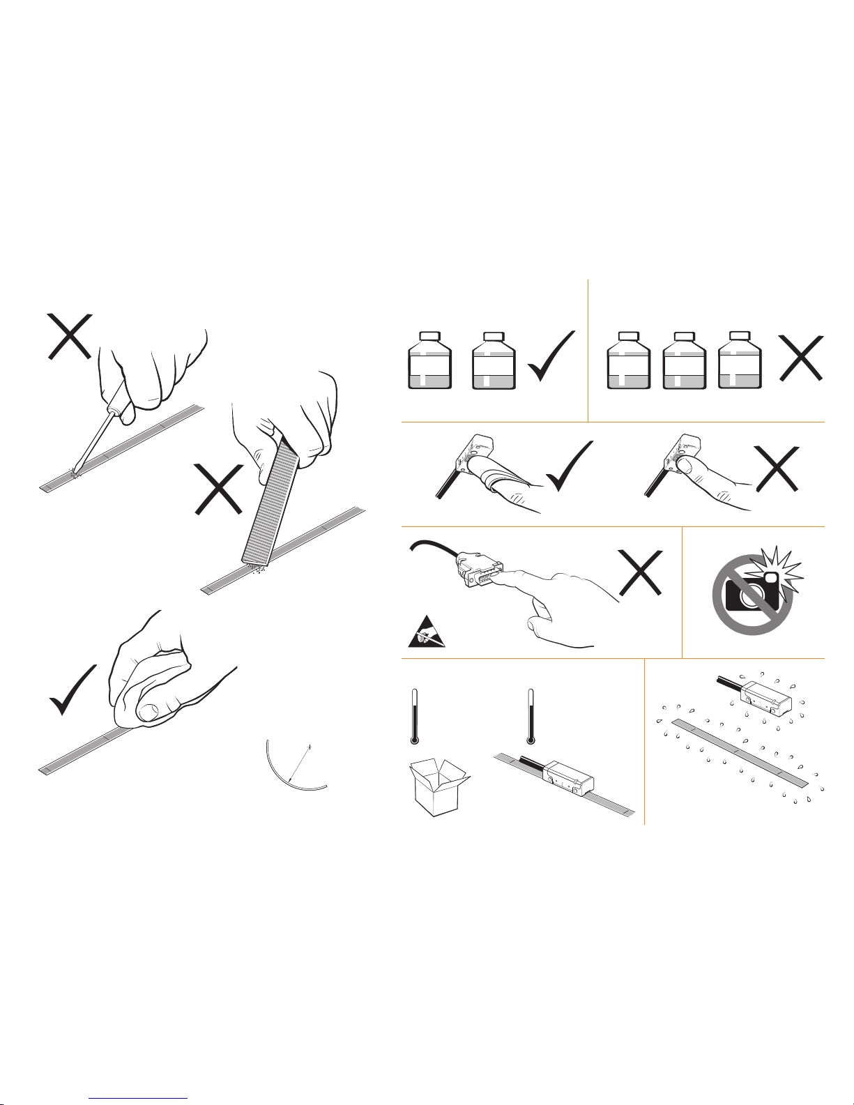
+70 °C
−20 °C
Minimum bend radius
RTLC40-S – 150 mm
RTLC40 – 50 mm
FASTRACK – 200 mm
NOTE: Ensure self-adhesive tape
is on the outside of bend radius.
95% relative humidity
(non-condensing)
to EN 60068-2-78
Humidity
Storage
+70 °C
0 °C
Operating
Storage and handling
N-heptane
CH
3
(CH2)5CH
3
Propan-2-ol
CH3CHOHCH
3
Scale and readhead
Readhead only
Acetone
CH3COCH
3
Methylated
Spirits
Chlorinated
Solvents
QUANTiC linear installation guide
Page 5
3
QUANTiC linear installation guide
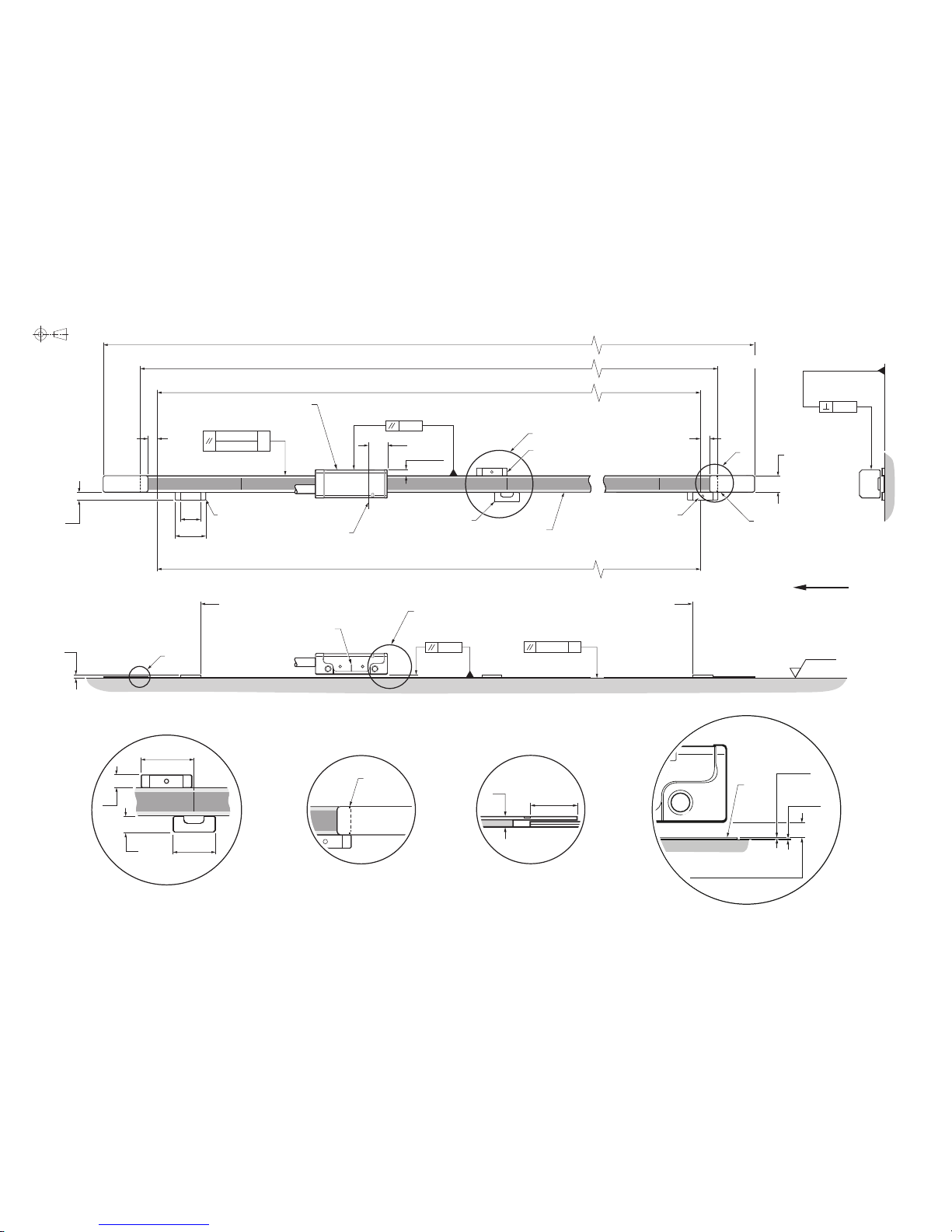
RTLC40-S: Installation drawing (adhesive datum clamp)
Dimensions and tolerances in mm
Scale length (L)
Overall length (L+37)
Measuring length ML = (L−17) (ML = (L−32 ) with dual limits)
Readhead optical detector position at extent of travel
Nominal P limit trigger point
Q limit magnet†
(A-9653-0139)
(Dimensions as P limit)
Reference mark selector magnet†
(A-9653-0143)
B
Optical centreline
(Incremental and reference mark)
5
Optional end cover
(Pair A-9585-0035)
5
8
START (see page 4)
A
C
End cover
alignment
indicator
0.5
F
0.2/100
0.05
F
F = axis of motion
Nominal Q limit trigger point
Ra 3.2
0.8
3.5
Detail A
12
3.7
4.5
Datum clamp
(A-9585-0028)
Detail CDetail B
15 ±1
10
15
3.7
0.12
(Roll tol. ±0.8°)
1.5
*
D
Detail D
0.6
(Pitch tol. ±1°)
0.55
(Yaw tol. ±0.9°)
2.75 ±0.5
Scale
reading
surface
Scale
thickness
0.2
Adhesive
thickness
0.2
Calibration rideheight: 2.1 ±0.2
Operating rideheight: 2.1 ±0.28
*
Dimension from substrate surface. †Bolted reference mark selector magnet and limit magnets available. See page 5 for details.
NOTE: The reference mark selector and limit actuator locations are correct for the readhead orientation shown.
F = axis of motion
P limit magnet†
(A-9653-0138)
QUANTiC
readhead
RTLC40-S
scale
FINISH (see page 4)
Forward direction of readhead
relative to scale
P and Q limit
switch sensor position
9.2
Page 6
4
QUANTiC linear installation guide
9
Remove applicator and, if necessary,
adhere the remaining scale manually.
Apply rm nger pressure via a clean
lint-free cloth along the length of the
scale after application to ensure
complete adhesion.
10
Clean scale using Renishaw scale
cleaning wipes (A-9523-4040) or
a clean, dry, lint-free cloth.
5
Move axis to scale START position, leaving enough room for the scale
to be inserted through the applicator, as shown below.
6
Begin to remove the backing paper from the scale and insert scale into
the applicator up to the ‘START’ point (as shown). Ensure backing paper
is routed under the splitter screw.
7
Apply nger pressure to the scale at the ‘START’ point, using a clean
lint-free cloth, to ensure scale end adheres well to the substrate.
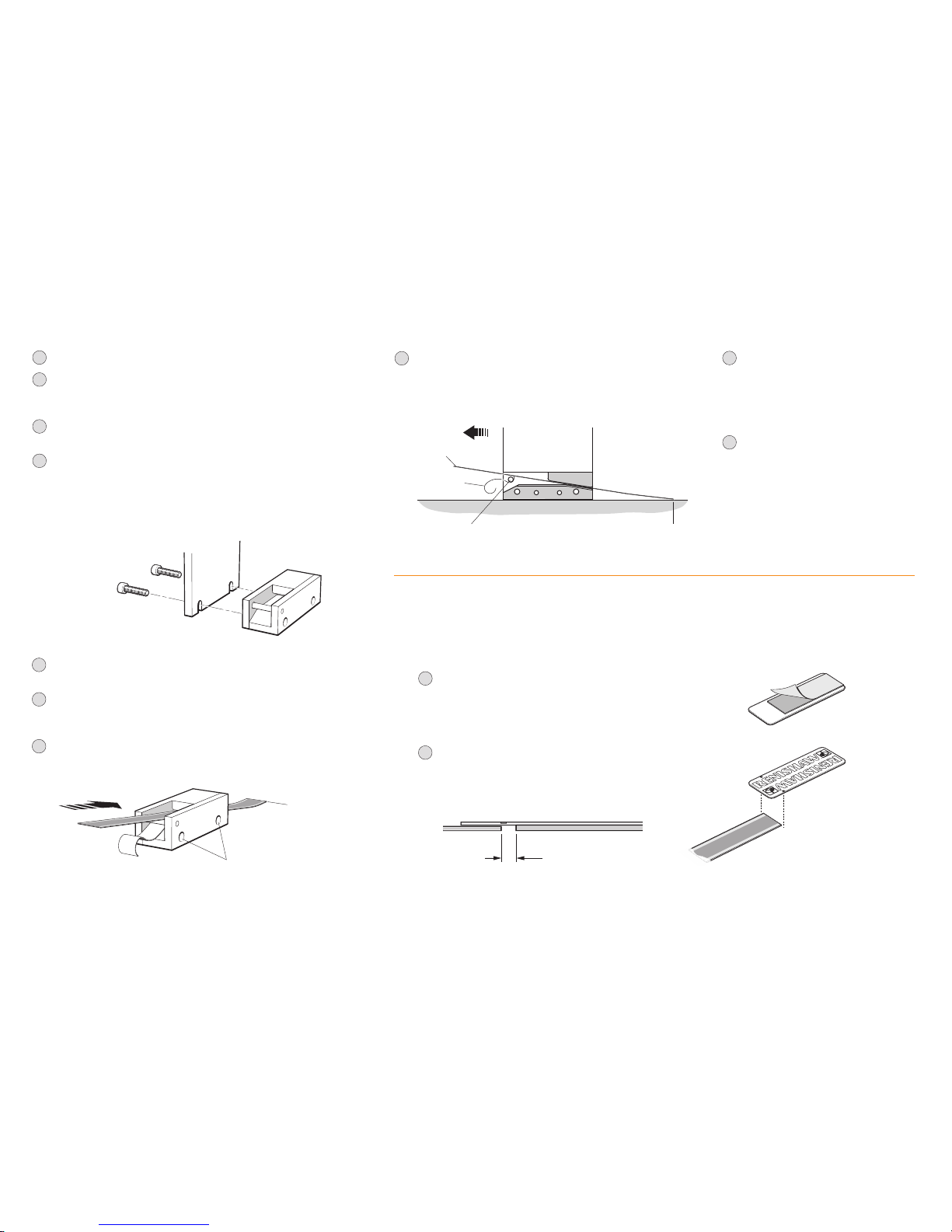
RTLC40-S: Scale application
Scale applicator (A-9589-0115) is designed for use with RTLC40-S scale.
1
Allow scale to acclimatise to installation environment prior to installation.
2
Mark out the ‘START’ and ‘FINISH’ points for the scale on the axis substrate
– ensure that there is room for the optional end covers if required
(see ‘RTLC40-S: Installation drawing’).
3
Thoroughly clean and degrease the substrate using recommended solvents
(see 'Storage and handling'). Allow substrate to dry before applying scale.
4
Mount the scale applicator to the readhead mounting bracket using
M2.5 screws. Place the shim supplied with the readhead between the
applicator and substrate to set the nominal height.
NOTE: Scale applicator can be mounted either way round to enable
easiest orientation for scale installation.
Side mounting scale applicator
(A-9589-0115)
8
Slowly and smoothly move the applicator through the entire axis
of travel, ensuring the backing paper is pulled manually from the
scale and does not catch under the applicator.
START
RTLC40-S
Backing tape
Splitter screw
Direction of scale application
M2.5 mounting holes
START
RTLC40-S: End covers
The end cover kit (A-9585-0035) is designed to be used with RTLC40-S scale.
NOTE: End covers are optional and can be tted before or after readhead installation.
1
Remove the backing tape from the adhesive tape on the back of
the end cover.
2
Align marker on the edges of the end cover with the end of the scale
and place end cover over the scale.
NOTE: There will be a gap* between the end of the scale and
the adhesive tape on the end cover.
*
gap
Page 7
5
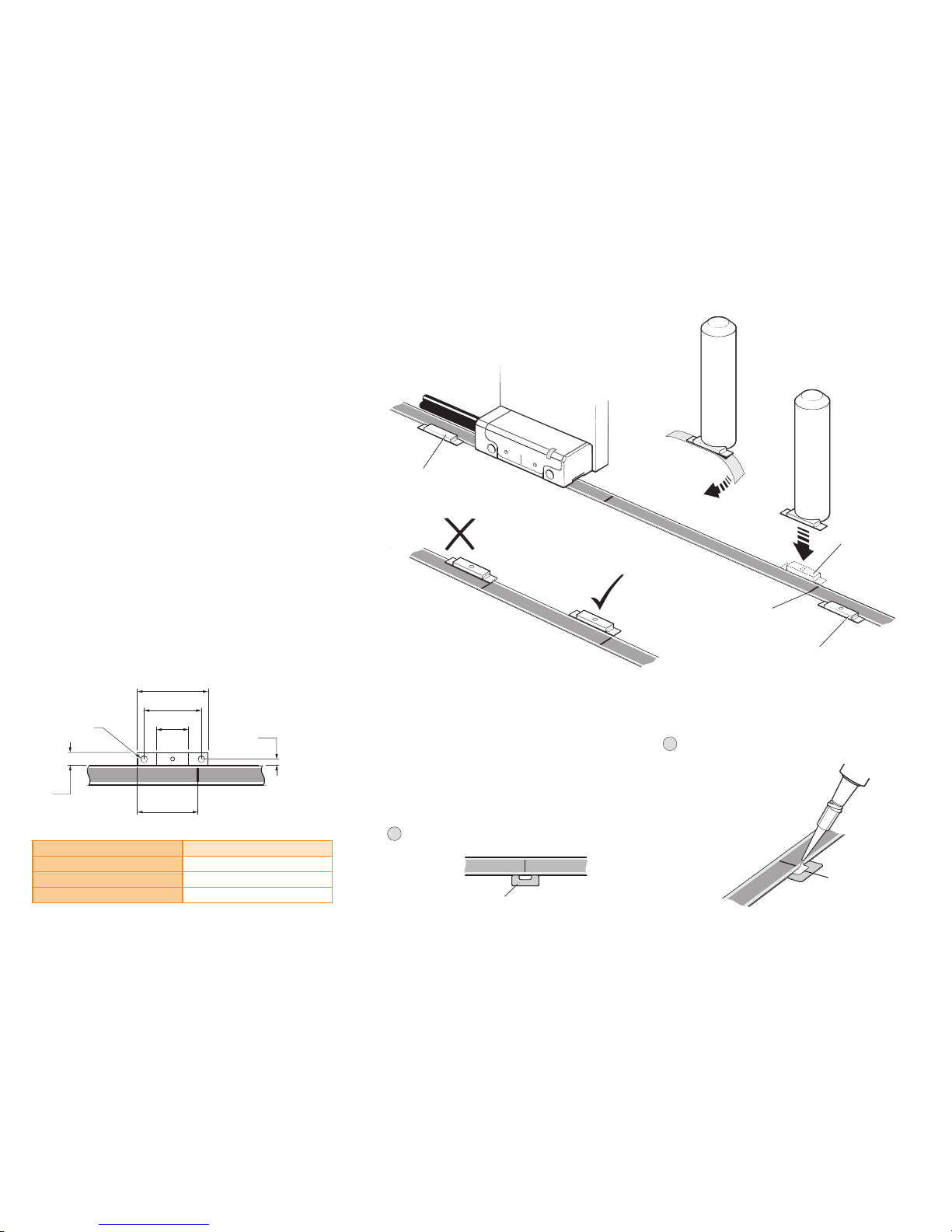
RTLC40-S: Reference mark selector and limit magnet installation
IMPORTANT: Allow 24 hours after scale application before tting magnets.
For accuracy and ease of positioning of reference mark selector and limit magnets,
the applicator tool (A-9653-0201) should be used. The magnet should be attached
to the applicator tool as shown. Limit magnets can be positioned at any user
dened location along the scale, but the reference mark selector magnet should
be positioned adjacent to the chosen IN-TRAC reference mark as shown.
As the QUANTiC readhead passes the reference mark selector magnet or limit
switch magnet, a force of up to 0.2 N is generated between the magnet and the
concentrators on the readhead. The design of the bracket should be sufciently
stiff so that it is able to tolerate such force without distorting.
Following the clamping instructions on the scale installation will prevent this
magnetic force from disturbing the scale.
NOTE: Reference and limit magnets may creep when inuenced by magnetic
materials in close proximity. In such cases, they should be held in place using
an additional llet of epoxy glue or similar along the outer edge of the
magnet assembly. Optional bolted reference and limit magnets are available.
Limit trigger point
The limit output is nominally asserted when the readhead limit switch sensor passes
the limit magnet leading edge, but can trigger up to 3 mm before that edge.
(See ‘RTLC40-S: Installation drawing’).
NOTE: External magnetic elds greater than 6mT, in the vicinity of the readhead,
may cause false activation of the limit and reference sensors.
Optional bolted reference mark selector and limit magnets
QUANTiC linear installation guide
2
Place a small amount of adhesive (Loctite® 435™)
in the cut-out on the datum clamp,
ensuring none of the adhesive
wicks onto the scale surface.
Dispensing tips P-TL50-0209
are available.
Ensure the adhesive
wicks along the entire
length of cut-out.
Remove
self-adhesive
backing paper
Reference mark
selector magnet
IN-TRAC
reference mark
Q limit magnet
Applicator tool
(A-9653-0201)
P limit magnet
1
Place the datum clamp with cut-out against the scale at
the chosen location.
A-9585-0028
22
18
10
3.7
Ø2.2
*
1.85
18.5 ±1
The datum clamp (A-9585-0028) xes the RTLC40-S scale rigidly
to the substrate at the location chosen. The metrology of the
system may be compromised if the datum clamp is not used.
The datum clamp does not need to be tted adjacent to a
reference mark. It can be positioned anywhere along the axis
depending upon the customers’ requirements.
*
Supplied with 2 x M2 x 4 screws.
RTLC40-S: Datum clamp
IMPORTANT: Allow 24 hours after scale application before tting datum clamp.
NOTE: The reference mark selector
and limit actuator locations are correct
for the readhead orientation shown.
Bolted magnet type Part number
P limit A-9653-0292
Q limit A-9653-0291
Reference mark selector A-9653-0290
Page 8

6
QUANTiC linear installation guide
QUANTiC
readhead
RTLC40 scale
FASTRACK
Ra 3.2
Optional end cover
(Pair A-9589-0058)
18
5
A
Do not cut FASTRACK
over shaded areas
2.25 ±0.5
18 ±0.1
35 max
Overall length (L+12)
Scale length (L)
Measuring length ML = (L−10)
(ML=(L−25 ) with dual limits)
10 max (gap)
1 min (gap)
Optical centreline (Incremental and reference mark)
Detail A
0.1/100
0.5
F
F = axis of motion
0.05
F
F = axis of motion
FASTRACK length = (L−24 )
*
*
Assumes 1 mm gap between scale and end covers and zero gap between FASTRACK and end covers.
†
Dimension from FASTRACK surface. ‡For alternative mechanical datum clamp methods see page 8.
NOTES: Minimum recommended FASTRACK length = 100 mm. The reference mark selector and limit actuator locations are correct for the readhead orientation shown.
RTLC40/FASTRACK: Installation drawing (adhesive datum clamp
‡
)
Nominal P limit trigger point
Nominal Q limit trigger point
P limit magnet
(A-9653-0138)
Q limit magnet
(A-9653-0139)
(Dimensions as P limit)
Reference mark selector magnet
(A-9653-0143) (Dimensions as P limit)
10
15
3.7
0.12
(Roll tol. ±0.8°)
0.55
(Yaw tol. ±0.9°)
1.5
†
0.6
(Pitch tol. ±1°)
B
Detail B
15 ±1
2 locations
for spots of Loctite® 435
™
(P-AD03-0012) to secure axis
datum position
‡
Dimensions and tolerances in mm
C
FASTRACK
thickness
0.4
Calibration rideheight: 1.9 ± 0.17
Operating rideheight: 1.9 ± 0.25
Detail C
Forward direction of readhead
relative to scale
P and Q limit
switch sensor position
9.2
Page 9

RTLC40/FASTRACK: FASTRACK and scale application
During handling or installation of FASTRACK suitable gloves should be worn to protect against injury from sharp edges.
2
Thoroughly clean and degrease
the substrate and allow to dry.
For FASTRACK location a ledge,
separate straight edge(s) or
dowels can be used.
Check alignment of ledge/separate
straight edge(s) with respect to
axis of motion
(see ‘RTLC40/FASTRACK:
Installation drawing’).
1
If required cut FASTRACK and scale to length
(separately) using guillotine (A-9589-0071)
after referring to installation drawing.
Guillotine should be held securely in place,
using a suitable vice or clamping method.
Feed FASTRACK or scale through the
guillotine as shown, and place guillotine
press block down onto the FASTRACK/scale.
Ensure the block is in the correct orientation
(as shown). Whilst holding the block in place,
in a smooth motion, pull down the lever to cut
through the FASTRACK/scale.
Before sticking FASTRACK to
the substrate bend the centre
section upwards slightly using
a small pair of pliers.
3
4
Remove backing liner and stick to substrate, locating
against ledge/separate straight edge(s) or dowels.
Ensure complete adhesion to the substrate by
applying rm nger pressure along the length
of the FASTRACK from the centre outwards
towards each end using a lint-free cloth
if required.
NOTE: Allow the FASTRACK a minimum
of 20 minutes to adhere before removing
the centre section.
IMPORTANT: Wear suitable
protective gloves whilst
carrying out this procedure
to avoid risk of cuts.
5
Engage centre section removal tool and with consistent
forward pressure remove centre section.
If the ledge method or similar is used
then the appropriate side panel on
the removal tool (A-9589-0122)
will need to be removed
as shown.
Ledge
Side panels
DO NOT CUT
FASTRACK
in these
areas
Guillotine
press block
7
QUANTiC linear installation guide
Page 10

8
QUANTiC linear installation guide
RTLC40/FASTRACK : Scale datum
The datum clamp xes the RTLC40 scale rigidly to the substrate at the location chosen.
The metrology of the system may be compromised if the datum clamp is not used.
The datum clamp does not need to be tted adjacent to a reference mark.
It can be positioned anywhere along the axis depending upon the customer’s requirements.
Mechanical clamp
Adhesive clamp
Using dispensing tip P-TL50-0209 apply Loctite 435
between scale and FASTRACK so it wicks underneath
adjacent to user selected datum location as shown.
NOTE: Drawing shows the scale datum adjacent
to the chosen reference mark.
RTLC40/FASTRACK : FASTRACK and scale application (Continued)
6
Slide RTLC scale into the FASTRACK ensuring the
scale is fed under the projections as shown.
Scale can be installed manually by either pulling or
pushing it through the FASTRACK carrier.
Alternatively use the optional
scale installation tool
(A-9589-0420) as shown,
for easy installation.
Ensure a gap
>1 mm
Projections
NOTE: For instructions on how to use the
scale installation tool, download ‘User guide
– RTL* scale installation tool (A-9589-0420)’
from the website at
www.renishaw.com/encoderinstallationguides.
IMPORTANT: If manually installing
the scale using fingers, suitable
gloves should be worn to protect
against injury from sharp edges.
7
Optional: x self-adhesive end covers
ensuring a gap of at least 1 mm between
the end of the scale and the end cover
8
Clean FASTRACK and scale
using a lint-free cloth
NOTE: When reference mark and
datum clamp aligned as shown,
reference output will be positionally
repeatable with respect to substrate.
Reference mark
selector magnet
3
Do not place clamp tip
over shaded area
IN-TRAC reference mark
12
25
RTLC40 clamp
(A-9589-0077)
M3 x 6 low head screw,
supplied with clamp
†
15 ±1
†
Additional screws available (Pack of 25 A-9584-2047)
NOTE: Only apply Loctite 435 in
these gaps to ensure best bond.
Loctite 435 will wick under the
scale to lock it to the substrate.
16
12
2.3
1.7
5 min
thread
depth
Page 11

9
QUANTiC linear installation guide
NOTE: All limit and reference selector magnets should be
aligned with the outer edges of the FASTRACK.
Limit trigger point
The limit output is nominally asserted when the readhead
limit switch sensor passes the limit magnet leading edge,
but can trigger up to 3 mm before that edge.
(See ‘RTLC40/FASTRACK : Installation drawing’).
NOTE: External magnetic elds greater than 6mT, in the
vicinity of the readhead, may cause false activation of
the limit and reference sensors.
P limit
magnet
Applicator tool
(A-9653-0201)
Remove
self-adhesive
backing paper
IN-TRAC
reference mark
Q limit magnet
RTLC40/FASTRACK : Reference mark selector and limit magnet installation
For accuracy and ease of positioning of reference mark selector and limit magnets, the applicator tool (A-9653-0201) should be used.
The magnet should be attached to the applicator tool as shown below and aligned with the outer edge of the FASTRACK.
Limit magnets can be positioned at any user dened location along the FASTRACK, but the reference mark selector
magnet should be positioned adjacent to the chosen IN-TRAC reference mark as shown below.
As the QUANTiC readhead passes the reference mark selector magnet or limit switch magnet, a force of up to 0.2 N
is generated between the magnet and the concentrators on the readhead. The design of the bracket should be
sufciently stiff so that it is able to tolerate such force without distorting. Following the clamping instructions on
the scale installation will prevent this magnetic force from disturbing the scale.
NOTE: Reference and limit magnets may creep when inuenced by magnetic materials
in close proximity. In such cases, they should be held in place using an additional
llet of epoxy glue or similar along the outer edge of the magnet assembly.
NOTE: The reference mark selector and limit actuator
locations are correct for readhead orientation shown
Reference mark
selector magnet
Page 12

10
QUANTiC linear installation guide
QUANTiC quick-start guide
This section is a quick-start guide to installing a QUANTiC readhead.
More detailed information on installing the readhead is contained on page 11 and page 12 of this installation guide.
The optional Advanced Diagnostic Tool ADTi-100* (A-6165-0100) and ADT View software† can be used to aid installation and calibration.
INSTALLATION
Ensure scale, readhead optical window and mounting faces are clean and free from obstructions.
If required, ensure reference mark selector magnet is correctly positioned, see relevant installation drawing.
Connect the readhead to receiving electronics and power-up. The set-up LED on the readhead will ash.
Install and align the readhead to maximise signal strength over the full axis of travel as indicated by a Green ashing LED.
CALIBRATION
Cycle the power to the readhead to initiate the calibration routine. The LED will single ash Blue.
Move the readhead along the scale at slow speed (<100 mm/s), without passing a reference mark, until the LED starts double ashing Blue.
The system is now calibrated and ready for use. Calibration values, Automatic Gain Control (AGC) and Automatic Offset Control (AOC) status, are stored in readhead non-volatile memory at power down.
NOTE: If calibration fails (LED remains single ashing blue), restore factory defaults by obscuring the readhead optical window on power-up (see page 12). Repeat the installation and calibration routine.
*
For more details refer to the ‘Advanced Diagnostic Tool ADTi-100 and ADT View software quick start guide’ (M-6195-9321) and ‘Advanced Diagnostic Tool ADTi-100 and ADT View software user guide’ (M-6195-9413).
†
The software can be downloaded for free from www.renishaw.com/adt.
Reference mark
Move the readhead back and forth over the selected
reference mark until the LED stops ashing.
No reference mark
If a reference mark is not being used, the calibration routine should now be
exited by cycling the power. The LED will stop ashing.
Page 13

11
QUANTiC linear installation guide
Readhead mounting and alignment
Mounting brackets
The bracket must have a at mounting surface and should provide adjustment to enable conformance to the
installation tolerances, allow adjustment to the rideheight of the readhead, and be sufciently stiff to prevent
deection or vibration of the readhead during operation.
Readhead set-up
Ensure that the scale, readhead optical window and mounting face are clean and free from obstructions.
NOTE: When cleaning readhead and scale apply cleaning uid sparingly, do not soak.
To set nominal rideheight, place the appropriate spacer with the aper ture under the optical centre of the readhead
to allow normal LED function during set-up procedure. RTLC40-S: green spacer, RTLC40/FASTRACK : black spacer.
Adjust the readhead to achieve a ashing Green LED along the full axis of travel. The faster the ash rate,
the closer it is to optimum set-up. The optional Advanced Diagnostic Tool ADTi-100 (A-6195-0100) and
ADT View software can be used to optimise signal strength in challenging installations.
See www.renishaw.com/adt for more information.
NOTE: When re-installing the readhead factory defaults should be restored, see page 12.
Roll
0° ±0.8°
Ya w
0° ±0.9°
Pitch
0° ±1°
Rideheight
2.1 ± 0.2 mm
Readhead LED diagnostics
Green Orange Red
ashing ashing ashing
Readhead set-up LED status
QUANTiC readhead and RTLC40-S
QUANTiC readhead and RTLC40/FASTRACK
Roll
0° ±0.8°
Ya w
0° ±0.9°
Pitch
0° ±1°
Rideheight
1.9 ±0.17 mm
from FASTRACK
top surface
IMPORTANT:
Use black spacer with
RTLC/FASTRACK
IMPORTANT:
Use green spacer
with RTLC-S
Mode LED Status
Installation mode
Green ashing Good set-up, maximise ash rate for optimum set-up
Orange ashing Poor set-up, adjust readhead to obtain Green ashing LED
Red ashing Poor set-up, adjust readhead to obtain Green ashing LED
Calibration mode
Blue single ashing Calibrating incremental signals
Blue double ashing Calibrating reference mark
Normal operation
Blue AGC on, optimum set-up
Green AGC off, optimum set-up
Red Poor set-up; signal may be too low for reliable operation
Blank ash Reference mark detected (visible indication at speed <100 mm/s only)
Alarm
4 red ashes Low signal, over signal, or overspeed; system in error
Page 14

12
QUANTiC linear installation guide
System calibration
NOTE: System calibration, restoring factory defaults, and enabling/disabling AGC functions can also be
carried out using the optional ADT and ADT View software. See www.renishaw.com/adt for more information.
Ensure signal strength has been optimised along the full axis of travel, the LED will be ashing Green.
Cycle the power to the readhead or connect the ‘Remote CAL’ output pin to 0 V for <3 seconds. The readhead
will then single ash Blue to indicate it is in calibration mode as detailed in ‘Readhead mounting and alignment’.
The readhead will only enter calibration mode if the LED is ashing Green.
Step 1 – Incremental signal calibration
uMove the readhead along the axis at slow speed (<100 mm/s), or less than the readhead maximum speed,
whichever is slowest, ensuring it does not pass a reference mark, until the LED starts double-ashing indicating
the incremental signals are now calibrated and the new settings are stored in the readhead memory.
uThe system is now ready for reference mark phasing. For systems without a reference mark, cycle the power
to the readhead or connect the ‘Remote CAL’ output pin to 0 V for < 3 seconds to exit calibration mode.
uIf the system does not automatically enter the reference mark phasing stage (LED continues single ashing)
the calibration of the incremental signals has failed. After ensuring failure is not due to overspeed (>100 mm/s),
or exceeding the readhead maximum speed, exit the calibration routine, restore factory defaults as detailed
below, and check the readhead installation and system cleanliness before repeating the calibration routine.
Step 2 – Reference mark phasing
uMove the readhead back and forth over the selected reference mark until the LED stops ashing and
remains solid Blue. The reference mark is now phased.
uThe system automatically exits the calibration routine and is ready for operation.
uAGC is automatically switched on once calibration is complete. To switch off AGC refer to the
‘Enabling/disabling AGC’ section.
uIf the LED continues double-ashing after repeatedly passing the chosen reference mark it is not being detected.
- Ensure that the correct readhead conguration is being used. Readheads can either output all
reference marks or only output a reference mark where a reference selector magnet is tted depending
on the options chosen when ordering.
- Check reference mark selector magnet is tted in the correct location relative to readhead orientation,
see ‘RTLC40-S installation drawing’.
Calibration routine manual exit
uTo exit the calibration routine at any stage cycle the power to the readhead or connect the ‘Remote CAL’
output pin to 0 V for <3 seconds. The LED will then stop ashing.
Restoring factory defaults
When re-installing the system, or in the case of continued calibration failure, factory defaults should
be restored.
To restore factory defaults:
uSwitch system off.
uObscure the readhead optical window (using the spacer supplied with the readhead ensuring the
cut-out is NOT under the optical window) or connect the ‘Remote CAL’ output pin to 0 V
uPower the readhead.
uRemove the spacer or, if using, the connection from the ‘Remote CAL’ output pin to 0 V.
uThe LED will start continuously ashing indicating factory defaults have been restored and the
readhead is in installation mode (ashing set-up LED).
uRepeat ‘Readhead set-up’ procedure.
Enabling/disabling AGC
The AGC is automatically enabled once the system has been calibrated (indicated by a Blue LED).
AGC can be manually switched off by connecting the ‘Remote CAL’ output pin to 0 V for >3 seconds
<10 seconds. The LED will then be solid Green.
LED Settings stored
Blue single ashing None, restore factory defaults and recalibrate
Blue double ashing Incremental only
Blue (auto-complete) Incremental and reference mark
Page 15

Troubleshooting
QUANTiC linear installation guide
13
Fault Cause Possible solutions
LED on the readhead is Blank There is no power to the readhead
u
Ensure 5 V supplied at the readhead
u
For cable variants check correct wiring of connector
LED on the readhead is Red and
I can’t get a Green LED
The signal strength is <50%
u
Check the readhead optical window and scale are clean and free from contamination
u
Restore factory defaults (see page 12) and check alignment of the readhead. In particular:
– Rideheight
– Ya w
– Offset
u
Check the scale is correct type (RTLC40)
Unable to get a Green LED over the
complete axis length
System run-out is not
within specication
u
Use a DTi gauge and check the run-out is within specications
u
Restore factory defaults
u
Realign readhead to obtain a Green ashing LED at the mid-point of the run-out
u
Recalibrate the system (see page 12)
Can’t initiate the calibration routine Signal size is <70%
u
Realign readhead to obtain a green ashing LED
During calibration the LED on the
readhead remains single ashing
Blue even after moving it along the
full axis length
The system has failed to calibrate the
incremental signals due to the signal
strength being <70%
u
Exit CAL mode and restore factory defaults (see page 12)
u
Check system set-up and realign the readhead to obtain a Green ashing LED along the full axis of travel
before recalibrating
During calibration the LED on the
readhead is double ashing Blue
even after moving it past the
reference mark several times
The readhead is not seeing a
reference mark
u
Ensure correct position of reference mark selector magnet
u
Ensure you are moving the readhead past your chosen reference mark several times
u
Check the readhead/selector magnet orientation
u
Check the readhead optical window and scale are clean and free from contamination
Page 16

QUANTiC linear installation guide
14
Troubleshooting (continued)
Fault Cause Possible solutions
No reference mark output
u
Ensure you are not over-speeding the readhead during calibration mode (maximum speed <100 mm/sec)
u
Calibrate the system (see page 12)
– If the system completes calibration mode then it has successfully seen and calibrated the reference mark
If you still don’t see a reference mark then check the system wiring
– If the system does not calibrate the reference mark (LED on the readhead remains double ashing Blue)
see above for possible solutions
Reference mark is not repeatable Only the chosen reference mark that has
been used in the calibration sequence is
repeatable, other reference marks may
not be phased
u
Ensure you are using the reference mark that has been calibrated for referencing your system
u
The readhead bracket must be stable and not allow any mechanical movement of the readhead
u
Clean the scale and readhead optical window and check for damage then recalibrate the system over
the chosen reference mark
LED on the readhead is ashing Red
over the reference mark
The reference mark is not phased
u
Ensure you are using the reference mark that has been calibrated for referencing your system as only this
reference mark will be guaranteed to remain phased
u
Clean the scale and readhead optical window and check for scratches then recalibrate the system over the
chosen reference mark (see page 12)
Multiple reference marks are
being output
The readhead reference mark option is
either option B or F, ‘All reference marks
are output’
u
Calibrate the system ensuring both Step 1 and Step 2 are completed (see page 12)
u
Ensure you calibrate the reference mark used for referencing your system as only this reference mark
will be guaranteed to remain phased
Page 17

QUANTiC linear installation guide
15
Dimensions and tolerances in mm
QUANTiC: Readhead dimensions
18
29
7.8
7.8
Optical centreline
(Incremental and reference mark)
Set-up LED
Reference mark selector sensor position
P and Q limit switch sensor position
Mounting faces
13.5
4.25
4.15
10
8.75
*
6 min
R>30 Dynamic bend radius
R>10 Static bend radius
35
23
11.5
Optical centreline marker
Ø 4.25 ±
0.2
5
2 off mounting holes M2.5 through,
counterbored Ø3 × 2.3 deep both sides.
NOTE: The recommended thread engagement is 5 min
(7.5 including counterbore) and the recommended
tightening torque is between 0.25 and 0.4 Nm.
*
Extent of mounting faces
2.5
Page 18

16
QUANTiC linear installation guide
15 way D-type connector (termination code D, H)
52 16
40
9 way D-type connector (termination code A)
52
16
31
12 way in-line circular connector (termination code X)
66
17
Output signals
*
For a readhead with a 1 m cable.
Speed
14 way JST connector (termination code J)
†
1
14
17
2.8
5
Clocked output
option
(MHz)
Maximum speed (m/s)
Minimum edge
separation*
(ns)
T
(10 µm )
D
(5 µm )
X
( 1 µm)
Z
(0.5 µm )
W
(0.2 µm )
Y
(0.1 µm )
H
(50 nm )
50 24 24 24 18.13 7.25 3.626 1.813 25.1
40 24 24 24 14.50 5.80 2.900 1.450 31.6
25 24 24 18.13 9.06 3.63 1.813 0.906 51.0
20 24 24 16.11 8.06 3.22 1.611 0.806 57.5
12 24 24 10.36 5.18 2.07 1.036 0.518 90.0
10 24 24 8.53 4.27 1.71 0.853 0.427 109
08 24 24 6.91 3.45 1.38 0.691 0.345 135
06 24 24 5.37 2.69 1.07 0.537 0.269 174
04 24 18.13 3.63 1.81 0.73 0.363 0.181 259
01 9.06 4.53 0.91 0.45 0.18 0.091 0.045 1038
Function Signal Colour
9 way D-type
(A)
15 way D-type
(D)
15 way D-type
alternative pin-out
(H)
12 way circular
connector
(X)
14 way JST
(J)
Power
5 V Brown 5 7, 8 4, 12 G 10
0 V White 1 2, 9 2, 10 H 1
Incremental
A
+ Red 2 14 1 M 7
− Blue 6 6 9 L 2
B
+ Yellow 4 13 3 J 11
− Green 8 5 11 K 9
Reference
mark
Z
+ Violet 3 12 14 D 8
− Grey 7 4 7 E 12
Limits
P Pink
–
11 8 A 14
Q Black
–
10 6 B 13
Alarm E − Orange
–
3 13 F 3
Remote CAL CAL Clear 9 1 5 C 4
Shield
–
Screen Case Case Case Case
Ferrule
†
Maximum of 20 insertion cycles for JST connector
Page 19

17
QUANTiC linear installation guide
Electrical connections
Grounding and shielding
Shield
Output
signals
5 V
Readhead
termination/connector
0 V
Customer
electronics
QUANTiC readhead
Recommended signal termination
Standard RS422A line receiver circuitry.
Capacitors recommended for improved noise immunity.
Customer
electronics
120R
A B Z−
Cable Z0 = 120R
Readhead
A B Z+
0 V
0 V
220 pF
220 pF
Single ended alarm signal termination
(Alarm signal not available with ’A’ cable termination)
Customer
electronics
5 V
1k8
4k7
4k7
100nF
100R
E−
Readhead
Limit output
(Limit output not available with ’A’ cable termination)
5 V to 24 V
R
*
P Q
*
Select R so that maximum current
does not exceed 10 mA.
Alternatively, use a suitable relay
or opto-isolator.
Remote CAL operation
CAL
0 V
Output specications
Digital output signals
Form – Square wave differential line driver to EIA RS422A (except limits P and Q)
Limits Open collector output, asynchronous pulse
(Limit output not available with ’A’ cable termination)
Repeatability
<0.1 mm
~ Length of limit actuator
P Q
Active high
Incremental† 2 channels A and B in quadrature (90° phase shifted)
Signal period P
Resolution S
A
B
Z
Reference
†
Synchronised pulse Z, duration as resolution.
Bi-directionally repeatable.
IMPORTANT: The shield should be connected to the machine earth (Field Ground).
For JST variants the ferrule should be connected to the machine earth.
Maximum readhead cable length: 3 m
Maximum extension cable length: Dependant on cable type, readhead cable length and clock speed.
Contact your local subsidiary for more information.
Remote operation of the CAL/AGC
is possible via CAL signal.
Alarm
Line driven (Asynchronous pulse)
(Not available with ’A’ cable termination)
Resolution
option code
P (
µm)
S (
µm)
T 40 10
D 20 5
X 4 1
Z 2 0.5
W 0.8 0.2
Y 0.4 0.1
H 0.2 0.05
†
Inverse signals not shown for clarity
E−
or 3-state alarm
Differentially transmitted signals forced open circuit
for >15 ms when alarm conditions valid.
Alarm asserted when:
– Signal amplitude <20% or >135%
– Readhead speed too high for reliable operation
>15 ms
NOTE: A wide reference mark option, outputting
a reference pulse for the duration of the signal
period is available.
Contact your local subsidiary for more information.
Page 20

18
QUANTiC linear installation guide
Power supply 5V −5%/+10% Typically 200 mA fully terminated
Power from a 5 V dc supply complying with the
requirements for SELV of standard IEC BS EN 60950-1
Ripple 200 mVpp maximum @ frequency up to 500 kHz
Temperature Storage −20 °C to +70 °C
Operating 0 °C to +70 °C
Humidity 95% relative humidity (non-condensing) to EN 60068-2-78
Sealing IP40
Acceleration (system) Operating 400 m/s², 3 axes
Shock (system) Operating 500 m/s², 11 ms, ½ sine, 3 axes
Vibration (readhead) Operating 100 m/s² max @ 55 Hz to 2000 Hz, 3 axes
(scale)
Operating 300 m/s² max @ 55 Hz to 2000 Hz, 3 axes
Mass Readhead 9 g
Cable 26 g/m
Readhead cable Single-shielded, outside diameter 4.25 ±0.25 mm
Flex life >20 × 106 cycles at 30 mm bend radius
UL recognised component
Maximum readhead cable length* 3 m
*Extension cables available. Contact your local Renishaw representative for further details
Renishaw encoder systems have been designed to the relevant EMC standards,
but must be correctly integrated to achieve EMC compliance. In particular,
attention to shielding arrangements is essential.
General specications
Form (H x W) RTLC40-S 0.4 mm x 8 mm (including adhesive)
RTLC40 0.2 mm x 8 mm
Datum xing RTLC40-S Loctite 435 with A-9585-0028 clamp
RTLC40 Loctite 435 or mechanical clamp (A-9589-0077)
Reference mark Customer selected IN-TRAC auto phase optical reference
mark repeatable to unit of resolution throughout specied
temperature and speed range
L ≤100 mm Single reference mark at scale centre
L >100 mm Reference marks at 50 mm spacing
(rst reference mark 50 mm from scale end)
Material RTLC40-S Hardened and tempered martensitic stainless steel tted
with a self-adhesive backing tape
RTLC40 Hardened and tempered martensitic stainless steel
Accuracy at 20 °C
(includes slope and linearity)
RTLC40 ±15 µm/m calibration traceable to International Standards
RTLC40H ±5 µm/m calibration traceable to International Standards
Linearity RTLC40 ±5 µm/m achievable with 2 point error correction
RTLC40H ±2.5 µm/m achievable with 2 point error correction
Coefcient of thermal expansion at 20 °C 10.1 ±0.2 µm/m/°C
Maximum length
10 m
†
Installation temperature 15 °C to 35 °C
†
For lengths >2 m FASTRACK with RTLC40 is recommended.
Form (H x W)
0.4 mm x 18 mm (including adhesive)
Material
Hardened and tempered martensitic stainless steel
Coefcient of thermal expansion at 20 °C 10.1 ±0.2 µm/m /°C
Mounting Self-adhesive backing tape
Minimum recommended length 100 mm
Maximum supplied length
25 m
Installation temperature 15 °C to 35 °C
RTLC40-S and RTLC scale technical specications
FASTRACK technical specications
Page 21

RSLM high accuracy linear encoder
Renishaw plc
New Mills, Wotton-under-Edge,
Gloucestershire GL12 8JR
United Kingdom
T +44 (0)1453 524524
F +44 (0)1453 524901
E uk@renishaw.com
www.renishaw.com
For worldwide contact details,
please visit our main website at
www.renishaw.com/contact
*M-9417-9089-03*
RENISHAW® and the probe symbol used in the RENISHAW logo are registered trade marks
of Renishaw plc in the United Kingdom and other countries.
apply innovation and names and designations of other Renishaw products and technologies
are trade marks of Renishaw plc or its subsidiaries.
Loctite® is a registered trademark of the Henkel Corporation.
© 2017-2018 Renishaw plc All rights reserved Issued 1118
 Loading...