

Page 1
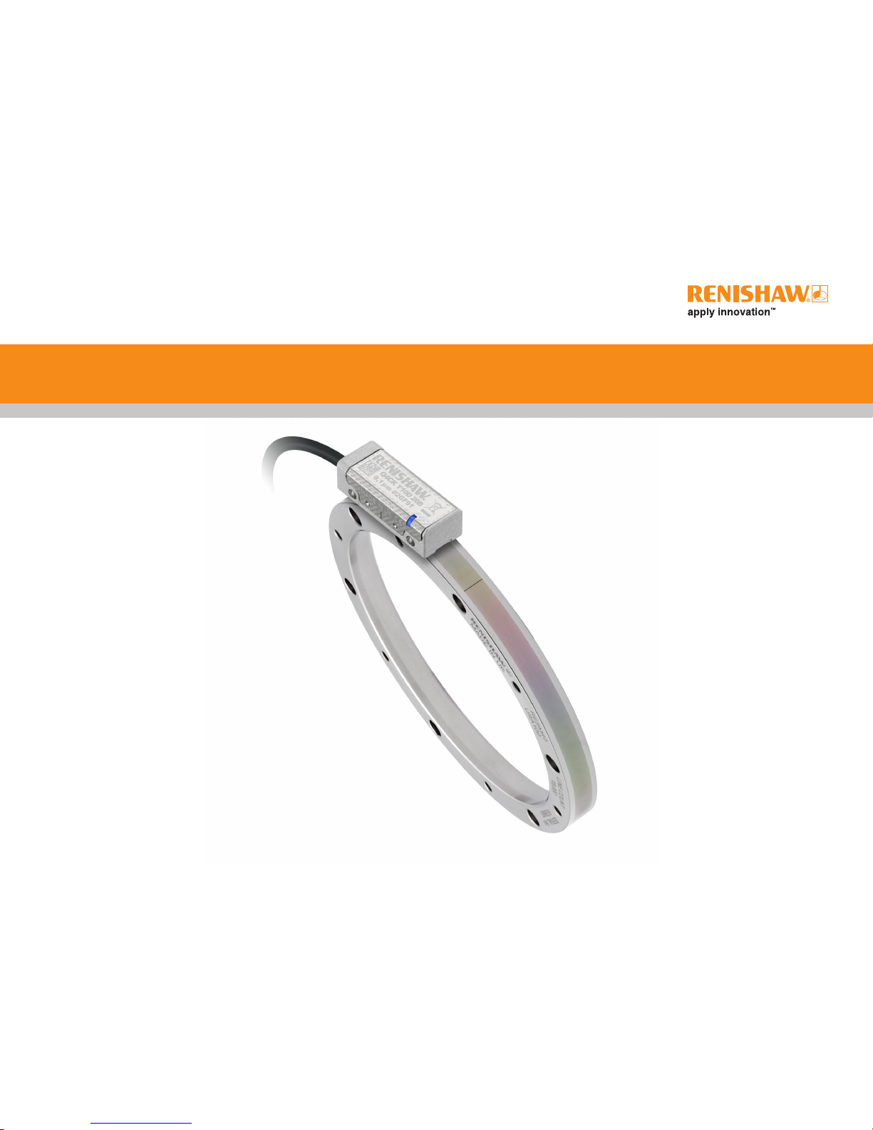
RSLM high accuracy linear encoder
Installation guide
M-9417-9201-01-A
QUANTiC™ RESM40 angle encoder system
Page 2

Contents
Product compliance 1
Storage and handling 2
RESM40
:
Installation drawing (‘A’ section) 3
Installation drawing (‘B’ section) 4
Selecting a mounting option 5
Taper mount method 5
Interference t method 7
QUANTiC quick-start guide 8
Readhead mounting and alignment 9
System calibration 10
Troubleshooting 11
QUANTiC:
Readhead dimensions 13
Output signals 14
Speed 14
Electrical connections 15
Output specications 15
General specications 16
RESM40 ring specications 16
QUANTiC RESM40 angle encoder system installation guide
Page 3

Disclaimer
RENISHAW HAS MADE CONSIDERABLE EFFORTS TO ENSURE THE CONTENT OF THIS DOCUMENT
IS CORRECT AT THE DATE OF PUBLICATION BUT MAKES NO WARRANTIES OR REPRESENTATIONS
REGARDING THE CONTENT. RENISHAW EXCLUDES LIABILITY, HOWSOEVER ARISING, FOR ANY
INACCURACIES IN THIS DOCUMENT.
Product compliance
C
Renishaw plc declares that QUANTiC complies with the applicable standards and regulations.
A copy of the EC Declaration of Conformity is available from our website www.renishaw.com
FCC compliance
This device complies with part 15 of the FCC Rules. Operation is subject to the following two conditions:
(1) This device may not cause harmful interference, and (2) this device must accept any interference
received, including interference that may cause undesired operation.
The user is cautioned that any changes or modications not expressly approved by Renishaw plc or
authorised representative could void the user’s authority to operate the equipment.
This equipment has been tested and found to comply with the limits for a Class A digital device,
pursuant to part 15 of the FCC Rules. These limits are designed to provide reasonable protection
against harmful interference when the equipment is operated in a commercial environment.
This equipment generates, uses, and can radiate radio frequency energy and, if not installed
and used in accordance with the instruction manual, may cause harmful interference to radio
communications. Operation of this equipment in a residential area is likely to cause harmful
interference in which case the user will be required to correct the interference at his own expense.
NOTE: This unit was tested with shielded cables on the peripheral devices. Shielded cables must be
used with the unit to ensure compliance.
RoHS compliance
Compliant with EC directive 2011/65/EU (RoHS)
Patents
Features of Renishaw’s encoder systems and similar products are the subjects of the following
patents and patent applications:
EP1173731 US6775008 JP4750998 CN100543424 EP1766334
JP4932706 US7659992 CN100507454 EP1766335 IN281839
JP5386081 US7550710 CN101300463 EP1946048 JP5017275
US7624513 CN101310165 EP1957943 US7839296 CN108351229
EP3347681 JP2017042570 KR20180052676 US20180216972 WO2017203210
EP1094302 JP5442174 US6481115 CN1293983 EP10297440
GB2397040 JP4813018 US7723639 CN1314511 EP1469969
EP2390045 JP5002559 US8987633 US8466943 US7367128
JP4423196
Further information
Further information relating to the QUANTiC encoder range can be found in the QUANTiC system
Data sheet (L-9517-9778), Advanced Diagnostic Tool ADTi-100 Data sheet (L-9517-9699), Advanced
Diagnostic Tool ADTi-100 and ADT View software quick-start guide (M-6195-9321), and the Advanced
Diagnostic Tool ADTi-100 and ADT View software user guide (M-6195-9413). These can be downloaded
from our website www.renishaw.com/encoder and are also available from your local representative.
This document may not be copied or reproduced in whole or in part, or transferred to any other media or
language, by any means without the written prior permission of Renishaw. The publication of material within
this document does not imply freedom from the patent rights of Renishaw plc.
The use of this symbol on Renishaw products and/or accompanying documentation indicates that the product
should not be mixed with general household waste upon disposal. It is the responsibility of the end user to
dispose of this product at a designated collection point for waste electrical and electronic equipment (WEEE)
to enable reuse or recycling. Correct disposal of this product will help to save valuable resources and prevent
potential negative effects on the environment. For more information, please contact your local waste disposal
service or Renishaw distributor.
1
QUANTiC RESM40 angle encoder system installation guide
The packaging of our products contains the following materials and can be recycled.
Packaging Component Material ISO 11469 Recycling Guidance
Outer box
Cardboard Not applicable Recyclable
Polypropylene PP Recyclable
Inserts
Low Density Polyethylene Foam LDPE Recyclable
Cardboard Not applicable Recyclable
Bags
High Density Polyethylene Bag HDPE Recyclable
Metalised Polyethylene PE Recyclable
Page 4

2
+70 °C
−20 °C
95% relative humidity
(non-condensing)
to EN 60068-2-78
Humidity
Storage
+70 °C
0 °C
Operating
Storage and handling
QUANTiC RESM40 angle encoder system installation guide
RESM40 is a non-contact optical encoder that
provides good immunity against contaminants
such as dust, ngerprints and light oils.
However, in harsh environments such as machine
tool applications, protection should be provided
to prevent ingress of coolant or oil.
N-heptane
CH3(CH2)5CH
3
Propan-2-ol
CH3CHOHCH
3
Ring and readhead
Acetone
CH3COCH
3
Methylated
Spirits
Chlorinated
Solvents
Readhead only
Acetone
CH3COCH
3
Methylated
Spirits
Chlorinated
Solvents
Ring only
Page 5
3
QUANTiC RESM40 angle encoder system installation guide
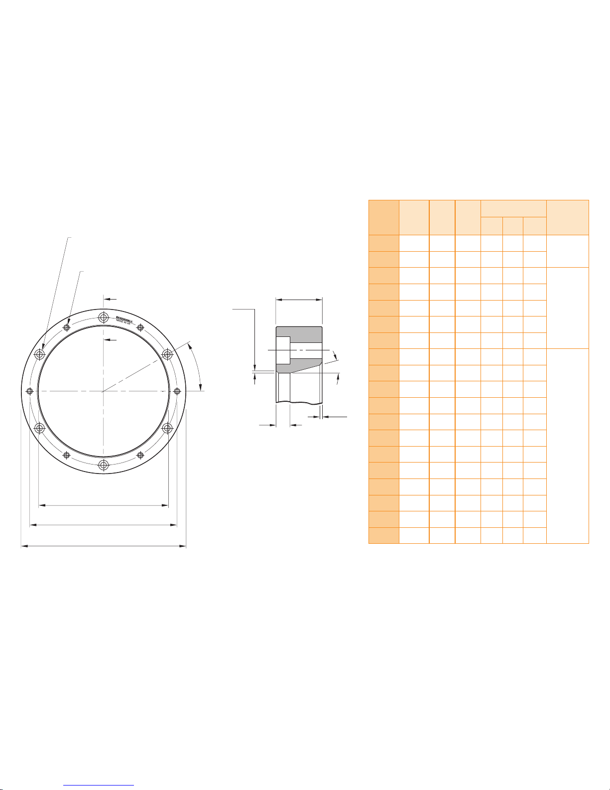
RESM40 installation drawing (‘A’ section)
Dimensions and tolerances in mm
N holes equally spaced on PCD ØDH Ø3.5
through c/bore top face Ø6 × 3 deep
N holes equally spaced on PCD ØDH M3 x 0.5
through c/bore top face Ø3.5 × 4 deep
A
θ
A
ØDI
ØDH
ØDO
NOTE: θ is the angle between one tapped hole and the adjacent
clearance hole. The angle between two clearance holes is 2θ.
*
There are no tapped holes on the 489mm ring.
Section A–A
10
0.5 × 45°
15° ±0.2°
1 x 45°
3
Nominal
external
diameter
(mm)
Line
count
DO
(mm)
DI
(mm)
Mounting holes Readhead
model
DH
(mm)
N
θ
52 4 096
52.20
52.10
30.04
30.00
40 6 30°
Q4CL
57 4 500
57.35
57.25
37.04
37.00
47 6 30°
75 5 920
75.40
75.30
55.04
55.00
65 6 30°
Q4CK
100 7 872
100.30
100.20
80.04
80.00
90 6 30°
103 8 100
103.20
103.00
80.04
80.00
90 6 30°
104 8 192
104.40
104.20
80.04
80.00
90 6 30°
115 9 000
114.70
114.50
95.04
95.00
105 6 30°
150 11 800
150.40
150.20
130.04
130.00
140 9 20°
Q4BJ
200 15 744
200.40
200.20
180.04
180.00
190 12 15°
206 16 200
206.50
206.10
186.05
186.00
196 12 15°
209 16 384
208.80
208.40
186.05
186.00
196 12 15°
229 18 000
229.40
229.00
209.05
209.00
219 12 15°
255 20 000
254.80
254.40
235.06
235.00
245 12 15°
300 23 600
300.40
300.20
280.06
280.00
290 16 11.25°
350 27 520
350.40
350.20
330.06
330.00
340 16 11.25°
413 32 400
412.70
412.30
392.08
392.00
402 18 10°
417 32 768
417.40
417.00
380.10
380.00
390 18 10°
489 38 400
489.12
488.72
451.10
450.90
462 20
18°
*
550 43 200
550.20
549.80
510.10
510.00
520 20 9°
Page 6
4
QUANTiC RESM40 angle encoder system installation guide
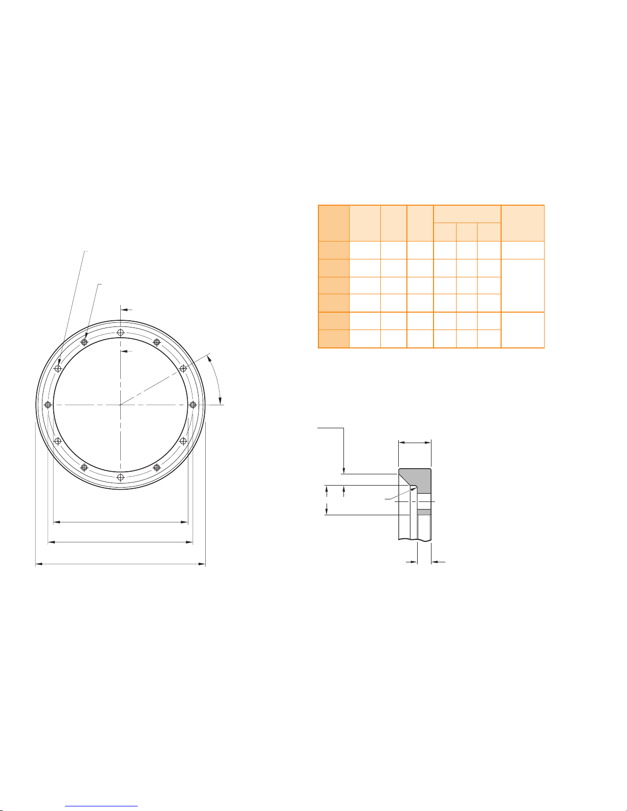
RESM40 installation drawing (‘B’ section)
Dimensions and tolerances in mm
N holes equally spaced on PCD ØDH Ø3.5 through
N holes equally spaced on PCD ØDH M3 × 0.5 through
A
θ
A
ØDI
ØDH
ØDO
NOTE: θ is the angle between one tapped hole and the adjacent clearance hole.
The angle between two clearance holes is 2θ.
Section A–A
7
2.5 × 45°
3
R0.5
6.5
Nominal
external
diameter
(mm)
Line
count
DO
(mm)
DI
(mm)
Mounting holes Readhead
model
DH
(mm)
N
θ
52 4 096
52.20
52.10
32.04
32.00
38 6 30° Q4CL
75 5 920
75.40
75.30
55.04
55.00
61 6 30°
Q4CK100 7 872
100.30
100.20
80.04
80.00
86 6 30°
115 9 000
114.70
114.50
95.04
95.00
101 6 30°
150 11 800
150.40
150.20
130.04
130.00
136 9 20°
Q4BJ
200 15 744
200.40
200.20
180.04
180.00
186 12 15°
Page 7

5
QUANTiC RESM40 angle encoder system installation guide
Taper Mount Interference t
‘A’ Section
‘B’ Section
Not applicable
Notes Recommended for all installations
X Enables simplest adjustment.
X Offers highest accuracy.
X Enables eccentricity to be compensated.
X Offers excellent mechanical stability
against thermal cycling, shock
and vibration.
X Minimises cost of substrate preparation.
Alternative installation
X Will not correct eccentricity of the
supporting shaft.
Select a mounting option
Taper mount method
Mounting shaft specications
Recommended taper roundness:
Recommended taper roundness when
using two heads and DSi:
Recommended taper diameter (DT):
Diameter (mm) Roundness
value (mm TIR)
≤115 0.025
150 to 225 0.050
≥300 0.075
Diameter (mm) Roundness
value (mm TIR)
≤115 0.0125
150 to 225 0.025
≥300 0.0375
Recommended surface nish ≤Ra 1.2.
NOTE: It is recommended that the mounting surface is a turned, rather than ground nish.
DO (mm) DT (mm)
52
33.85
33.65
57
40.85
40.65
75
58.85
58.65
100
83.85
83.65
103
83.85
83.65
104
83.85
83.65
115
98.85
98.65
DO (mm) DT (mm)
150
133.85
133.65
200
183.85
183.65
206
189.85
189.65
209
189.85
189.65
229
212.85
212.65
255
238.85
238.65
300
283.85
283.65
DO (mm) DT (mm)
350
333.85
333.65
413
395.85
395.65
417
383.85
383.65
489
454.85
454.65
550
513.85
513.65
DO = Nominal external diameter.
15° ±0.2°
*
Allow 2 mm for 417 mm, 489 mm and 550 mm rings only.
DT
7 min
1
*
Step 1
Page 8

6
QUANTiC RESM40 angle encoder system installation guide
X Clean shaft taper and internal taper of RESM40 as
recommended in the storage and handling section.
X Insert the rst screws:
- For RESM40 rings with 6, 9 or 18 mounting
holes, use 3 equally spaced M3 screws.
- For RESM40 rings with 12, 16 or 20 mounting
holes, use 4 equally spaced M3 screws.
NOTE: Do not lubricate screws.
NOTE: Recommended screw type M3 × 0.5:
ISO 4762/DIN 912 grade 10.9 minimum/ANSI
B18.3.1M.
X Insert the screws so that the RESM40 is loosely
connected to the shaft, then roughly align the ring
by eye and touch.
X Lightly tighten the screws. Use a Dial Test Indicator
(DTI) to check the radial displacement at the
screw locations.
NOTE: Disregard the radial displacement between
the screw locations.
Use a DTI with low exertion force to avoid
scratching the scale surface. A DTI with a ruby
ball stylus is recommended as a further precaution
against scratches.
X Adjust the screws to reduce the range of radial displacement. When adjusting, identify the screw
location with the lowest radial displacement and tighten that screw, aiming for the average of the highest
and lowest indicator readings.
X Repeat this process until the DTI readings are within ±5 µm at the screw locations.
NOTE: It may be necessary to loosen screws whilst tightening other screws.
NOTE: At this stage, the screws
should only be lightly tightened
(less than 0.5Nm) to allow
further nal adjustment.
X Insert the next screws:
- For RESM40 rings with 6, 9 or 12 mounting holes,
insert all the remaining M3 screws.
- For RESM40 rings with 16 mounting holes, inser t
3equally spaced M3 screws.
- For RESM40 rings with 18 mounting holes, inser t
6equally spaced M3 screws.
- For RESM40 rings with 20 mounting holes, inser t
8equally spaced M3 screws (in four groups of two)
between existing screws.
X As described in Step 2, adjust all the screws inserted thus
far, so that the radial displacement at each screw location
is within ±5 µm.
X Again, at this stage, the screws should only be lightly
tightened (less than 0.5 Nm).
NOTE: You may notice that the torque required to achieve
the radial displacement tolerance will be slightly higher
during step 3 than during step 2. This is normal.
Step 2
Step 3
DTI
Page 9

QUANTiC RESM40 angle encoder system installation guide
7
Interference t method
Mounting shaft specications
NOTES:
X Ensure that all screws are tightened to 1.6 Nm
X The recommended thread engagement is 6 mm
X 417, 489 and 550 mm rings should be taper mounted only.
DO = Nominal external diameter.
DS = Recommended shaft diameter to enable interference t.
*
52mm ‘B’ section ring DS (mm) =
32.033
32.017
DO
DS
DO (mm) DS (mm)
52
*
30.033
30.017
57
37.033
37.017
75
55.039
55.020
100
80.045
80.023
103
80.045
80.023
104
80.045
80.023
115
95.045
95.023
150
130.052
130.027
200
180.052
180.027
206
186.060
186.031
209
186.060
186.031
229
209.060
209.031
255
235.060
235.031
300
280.066
280.034
350
330.073
330.037
413
392.073
392.037
X Insert screws into the remaining mounting holes.
Diameter
(mm)
Recommended
torque range
(Nm)
≤115 1.5 - 2.1
150 to 255 0.8 - 1.1
300 to 413 0.5 - 0.7
≥417 1.2 - 1.7
X Rotate the RESM40 ring, measuring the radial
displacement at all of the screw locations.
X Tighten the screw with the lowest radial displacement so
that it matches the average radial displacement, whilst
ensuring the maximum torque specied in the table is
not exceeded.
X Again, rotate the RESM40 ring and re-check the radial
displacement at all of the screw locations, tightening
the screw with the lowest radial displacement so that it
matches the average.
X Repeat this process until the radial displacement at all
of the screw locations is within ±3 µm and that all screw
torques are within the specied range.
X Excessive tightening of screws can have a small effect on
accuracy. Please contact your local representative for
more details.
Step 4
Step 5
Page 10

8
QUANTiC RESM40 angle encoder system installation guide
QUANTiC quick-start guide
This section is a quick-start guide to installing a QUANTiC readhead.
More detailed information on installing the readhead is contained on page 9 and page 10 of this installation guide.
The optional Advanced Diagnostic Tool ADTi-100* (A-6165-0100) and ADT View software† can be used to aid installation and calibration.
INSTALLATION
Ensure scale, readhead optical window and mounting faces are clean and free from obstructions.
Connect the readhead to receiving electronics and power-up. The set-up LED on the readhead will ash.
Install and align the readhead to maximise signal strength over the full axis of rotation as indicated by a Green ashing LED.
CALIBRATION
Cycle the power to the readhead to initiate the calibration routine. The LED will single ash Blue.
Rotate the scale at slow speed (<100 mm/s), without passing the reference mark, until the LED starts double ashing Blue.
The system is now calibrated and ready for use. Calibration values, Automatic Gain Control (AGC) and Automatic Offset Control (AOC) status, are stored in readhead non-volatile memory at power down.
NOTE: If calibration fails (LED remains single ashing blue), restore factory defaults by obscuring the readhead optical window on power-up (see page 10). Repeat the installation and calibration routine.
*
For more details refer to the ‘Advanced Diagnostic Tool ADTi-100 and ADT View software quick start guide’ (M-6195-9321) and ‘Advanced Diagnostic Tool ADTi-100 and ADT View software user guide’ (M-6195-9413).
†
The software can be downloaded for free from www.renishaw.com/adt.
Reference mark
Move the readhead back and forth over the
reference mark until the LED stops ashing.
No reference mark
If a reference mark is not being used, the calibration routine should now be
exited by cycling the power. The LED will stop ashing.
Page 11

9
QUANTiC RESM40 angle encoder system installation guide
Readhead mounting and alignment
Mounting brackets
The bracket must have a at mounting surface and should provide adjustment to enable conformance to the
installation tolerances, allow adjustment to the rideheight of the readhead, and be sufciently stiff to prevent
deection or vibration of the readhead during operation.
Readhead set-up
Ensure that the scale, readhead optical window and mounting face are clean and free from obstructions.
NOTE: When cleaning readhead and scale apply cleaning uid sparingly, do not soak.
To set nominal rideheight, place the green spacer with the aper ture under the optical centre of the readhead to
allow normal LED function during set-up procedure. Adjust the readhead to achieve a ashing Green LED for a
complete rotation. The faster the ash rate, the closer it is to optimum set-up.
The optional Advanced Diagnostic Tool ADTi-100 (A-6195-0100) and ADT View software can be used to optimise
signal strength in challenging installations. See www.renishaw.com/adt for more information.
NOTE: When re-installing the readhead factory defaults should be restored, see page 10.
Roll
0° ±0.8°
Ya w
0° ±0.9°
Pitch
0° ±1°
Rideheight
2.1 ± 0.15 mm
Readhead LED diagnostics
Green Orange Red
ashing ashing ashing
Readhead set-up LED status
Green spacer
Mode LED Status
Installation mode
Green ashing Good set-up, maximise ash rate for optimum set-up
Orange ashing Poor set-up, adjust readhead to obtain Green ashing LED
Red ashing Poor set-up, adjust readhead to obtain Green ashing LED
Calibration mode
Blue single ashing Calibrating incremental signals
Blue double ashing Calibrating reference mark
Normal operation
Blue AGC on, optimum set-up
Green AGC off, optimum set-up
Red Poor set-up; signal may be too low for reliable operation
Blank ash Reference mark detected (visible indication at speed <100 mm/s only)
Alarm
4 red ashes Low signal, over signal, or overspeed; system in error
Reference mark position
IN-TRAC ™ reference mark is integrated in the scale, radially aligned with the centre of the mounting
hole to the left of the ‘Renishaw’ logo within ±0.5 mm. No external actuators or physical adjustment
are required.
Page 12

10
QUANTiC RESM40 angle encoder system installation guide
System calibration
NOTE: System calibration, restoring factory defaults, and enabling/disabling AGC functions can also
be carried out using the optional ADTi-100 and ADT View software. See www.renishaw.com/adt for
more information.
Ensure signal strength has been optimised over the full axis of rotation; the LED will be ashing Green.
Cycle the power to the readhead or connect the ‘Remote CAL’ output pin to 0 V for <3 seconds. The readhead
will then single ash Blue to indicate it is in calibration mode as detailed in ‘Readhead mounting and alignment’.
The readhead will only enter calibration mode if the LED is ashing Green.
Step 1 – Incremental signal calibration
XRotate the scale at slow speed (<100 mm/s) or less than the readhead maximum speed, whichever is
slowest, ensuring it does not pass a reference mark, until the LED starts double-ashing indicating the
incremental signals are now calibrated and the new settings are stored in the readhead memory.
XThe system is now ready for reference mark phasing. For systems without a reference mark, cycle the power
to the readhead or connect the ‘Remote CAL’ output pin to 0 V for < 3 seconds to exit calibration mode.
XIf the system does not automatically enter the reference mark phasing stage (LED continues single ashing)
the calibration of the incremental signals has failed. After ensuring failure is not due to overspeed (>100 mm/s),
or exceeding the readhead maximum speed, exit the calibration routine, restore factory defaults as detailed
below, and check the readhead installation and system cleanliness before repeating the calibration routine.
Step 2 – Reference mark phasing
XMove the readhead back and forth over the reference mark until the LED stops ashing and remains solid
Blue. The reference mark is now phased.
XThe system automatically exits the calibration routine and is ready for operation.
XAGC is automatically switched on once calibration is complete. To switch off AGC refer to the
‘Enabling/disabling AGC’ section.
XIf the LED continues double-ashing after repeatedly passing the reference mark it is not being detected.
Ensure correct readhead alignment.
Calibration routine manual exit
XTo exit the calibration routine at any stage cycle the power to the readhead or connect the ‘Remote CAL’
output pin to 0 V for <3 seconds. The LED will then stop ashing.
Restoring factory defaults
When re-installing the system, or in the case of continued calibration failure, factory defaults should
be restored.
To restore factory defaults:
XSwitch system off.
XObscure the readhead optical window (using the spacer supplied with the readhead ensuring the
cut-out is NOT under the optical window) or connect the ‘Remote CAL’ output pin to 0 V
XPower the readhead.
XRemove the spacer or, if using, the connection from the ‘Remote CAL’ output pin to 0 V.
XThe LED will start continuously ashing indicating factory defaults have been restored and the
readhead is in installation mode (ashing set-up LED).
XRepeat ‘Readhead set-up’ procedure.
Enabling/disabling AGC
The AGC is automatically enabled once the system has been calibrated (indicated by a Blue LED).
AGC can be manually switched off by connecting the ‘Remote CAL’ output pin to 0 V for >3 seconds
<10 seconds. The LED will then be solid Green.
LED Settings stored
Blue single ashing None, restore factory defaults and recalibrate
Blue double ashing Incremental only
Blue (auto-complete) Incremental and reference mark
Page 13

Troubleshooting
QUANTiC RESM40 angle encoder system installation guide
11
Fault Cause Possible solutions
LED on the readhead is Blank There is no power to the readhead
X
Ensure 5 V supplied at the readhead
X
For cable variants check correct wiring of connector
LED on the readhead is Red and
I can’t get a Green LED
The signal strength is <50%
X
Check the readhead optical window and scale are clean and free from contamination
X
Restore factory defaults (see page 10) and check alignment of the readhead
X
Check the scale is correct type (RESM40)
X
Check the readhead is the correct conguration for the ring diameter
Unable to get a Green LED around the
full axis of rotation
System run-out is not
within specication
X
Use a DTi gauge and check the run-out is within specications
X
Restore factory defaults
X
Realign readhead to obtain a Green ashing LED at the mid-point of the run-out
X
Recalibrate the system (see page 10)
Can’t initiate the calibration routine Signal size is <70%
X
Realign readhead to obtain a Green ashing LED
During calibration the LED on the
readhead remains single ashing
Blue even after moving around the full
axis of rotation
The system has failed to calibrate the
incremental signals due to the signal
strength being <70%
X
Exit CAL mode and restore factory defaults (see page 10)
X
Check system set-up and realign the readhead to obtain a Green ashing LED around the full axis of rotation
before recalibrating
During calibration the LED on the
readhead is double ashing Blue
even after moving it past the
reference mark several times
The readhead is not seeing a
reference mark
X
Ensure you are moving the readhead past the reference mark several times
X
Check the readhead optical window and scale are clean and free from contamination
X
Check the readhead is congured for ‘All reference marks’ to be output
Page 14

QUANTiC RESM40 angle encoder system installation guide
12
Troubleshooting (continued)
Fault Cause Possible solutions
No reference mark output
X
Ensure you are not over-speeding the readhead during calibration mode (maximum speed <100 mm/sec) or beyond
the readheads maximum speed (whichever is slower)
X
Calibrate the system (see page 10)
– If the system completes calibration mode then it has successfully seen and calibrated the reference mark
If you still don’t see a reference mark then check the system wiring
– If the system does not calibrate the reference mark (LED on the readhead remains double ashing Blue)
see above for possible solutions
Reference mark is not repeatable
X
The readhead bracket must be stable and not allow any mechanical movement of the readhead
X
Clean the scale and readhead optical window and check for damage then recalibrate the system ensuring
both step 1 and step 2 are completed (see page 10)
LED on the readhead is ashing Red
over the reference mark
The reference mark is not phased
X
Clean the scale and readhead optical window and check for scratches then recalibrate the system ensuring
both step 1 and step 2 are completed (see page 10)
Page 15

QUANTiC RESM40 angle encoder system installation guide
13
Dimensions and tolerances in mm
QUANTiC: Readhead dimensions
18
29
Optical centreline
(Incremental and reference mark)
Set-up LED
Mounting faces
13.5
4.25
4.15
10
8.75
*
6 min
R>30 Dynamic bend radius
R>10 Static bend radius
35
23
11.5
Ø 4.25 ±
0.25
2 off mounting holes M2.5 through, counterbored Ø3 x 2.3 deep both sides.
NOTE: The recommended thread engagement is 5 min (7.5 including counterbore)
and the recommended tightening torque is between 0.25 and 0.4 Nm.
*
Extent of mounting faces
12.1
4.6
Forward direction of ring
(increasing count)
Calibration rideheight: 2.1 ±0.15
Operating rideheight: 2.1 ±0.2
0.6
(Pitch tol. ±1°)
0.55
(Yaw tol. ±0.9°)
‘A’ section – 1.75 ±0.5
‘B’ section – 3.25 ±0.5
0.12
(Roll tol. ±0.8°)
Page 16

14
QUANTiC RESM40 angle encoder system installation guide
15 way D-type connector (termination code D, H)
52 16
40
9 way D-type connector (termination code A)
52
16
31
12 way in-line circular connector (termination code X)
66
17
Output signals
*
For a readhead with a 1 m cable.
Speed
14 way JST connector (termination code J)
†
1
14
17
2.8
5
Clocked output
option
(MHz)
Maximum speed (m/s)
Minimum edge
separation*
(ns)
T
(10 µm )
D
(5 µm )
X
( 1 µm)
Z
(0.5 µm )
W
(0.2 µm )
Y
(0.1 µm )
H
(50 nm )
50 24 24 24 18.13 7.25 3.626 1.813 25.1
40 24 24 24 14.50 5.80 2.900 1.450 31.6
25 24 24 18.13 9.06 3.63 1.813 0.906 51.0
20 24 24 16.11 8.06 3.22 1.611 0.806 57.5
12 24 24 10.36 5.18 2.07 1.036 0.518 90.0
10 24 24 8.53 4.27 1.71 0.853 0.427 109
08 24 24 6.91 3.45 1.38 0.691 0.345 135
06 24 24 5.37 2.69 1.07 0.537 0.269 174
04 24 18.13 3.63 1.81 0.73 0.363 0.181 259
01 9.06 4.53 0.91 0.45 0.18 0.091 0.045 1038
Function Signal Colour
9 way D-type
(A)
15 way D-type
(D)
15 way D-type
alternative pin-out
(H)
12 way circular
connector
(X)
14 way JST
(J)
Power
5 V Brown 5 7, 8 4, 12 G 10
0 V White 1 2, 9 2, 10 H 1
Incremental
A
+ Red 2 14 1 M 7
− Blue 6 6 9 L 2
B
+ Yellow 4 13 3 J 11
− Green 8 5 11 K 9
Reference
mark
Z
+ Violet 3 12 14 D 8
− Grey 7 4 7 E 12
Limits
P Pink
–
11 8 A 14
Q Black
–
10 6 B 13
Alarm E − Orange
–
3 13 F 3
Remote CAL CAL Clear 9 1 5 C 4
Shield
–
Screen Case Case Case Case
Ferrule
Angular speed depends on ring diameter – use the following equation to convert to rev/min.
Angular speed (rev/min) =
V × 1000 × 60
Where V = maximum linear speed (m/s) and D = external diameter of RESM40 ring (mm)
π D
†
Maximum of 20 insertion cycles for JST connector
Page 17

15
QUANTiC RESM40 angle encoder system installation guide
Electrical connections
Grounding and shielding
Shield
Output
signals
5 V
Readhead
termination/connector
0 V
Customer
electronics
QUANTiC readhead
Recommended signal termination
Standard RS422A line receiver circuitry.
Capacitors recommended for improved noise immunity.
Customer
electronics
120R
A B Z−
Cable Z0 = 120R
Readhead
A B Z+
0 V
0 V
220 pF
220 pF
Single ended alarm signal termination
(Alarm signal not available with ’A’ cable termination)
Customer
electronics
5 V
1k8
4k7
4k7
100nF
100R
E−
Readhead
Limit output
(Limit output not available with ’A’ cable termination)
5 V to 24 V
R*
P Q
*Select R so that maximum current
does not exceed 10 mA.
Alternatively, use a suitable relay
or opto-isolator.
Remote CAL operation
CAL
0 V
Output specications
Digital output signals
Form – Square wave differential line driver to EIA RS422A (except limits P and Q)
Limits Open collector output, asynchronous pulse
(Limit output not available with ’A’ cable termination)
Repeatability
<0.1 mm
~ Length of limit actuator
P Q
Active high
Incremental* 2 channels A and B in quadrature (90° phase shifted)
Signal period P
Resolution S
A
B
Z
Reference
*
Synchronised pulse Z, duration as resolution.
Bi-directionally repeatable.
IMPORTANT: The shield should be connected to the machine earth (Field Ground).
For JST variants the ferrule should be connected to the machine earth.
Maximum readhead cable length: 3 m
Maximum extension cable length: Dependant on cable type, readhead cable length and clock speed.
Contact your local subsidiary for more information.
Remote operation of the CAL/AGC
is possible via CAL signal.
Alarm
Line driven (Asynchronous pulse)
(Not available with ’A’ cable termination)
Resolution
option code
P (
µm)
S (
µm)
T 40 10
D 20 5
X 4 1
Z 2 0.5
W 0.8 0.2
Y 0.4 0.1
H 0.2 0.05
*
Inverse signals not shown for clarity
E−
or 3-state alarm
Differentially transmitted signals forced open circuit
for >15 ms when alarm conditions valid.
Alarm asserted when:
– Signal amplitude <20% or >135%
– Readhead speed too high for reliable operation
>15 ms
NOTE: A wide reference mark option, outputting
a reference pulse for the duration of the signal
period is available.
Contact your local subsidiary for more information.
Page 18

16
QUANTiC RESM40 angle encoder system installation guide
General specications
Power supply 5V −5%/+10% Typically 200 mA fully terminated
Power from a 5 V dc supply complying with the requirements
for SELV of standard IEC BS EN 60950-1
Ripple 200 mVpp maximum @ frequency up to 500 kHz
Temperature (system) Storage −20 °C to +70 °C
Operating 0 °C to +70 °C
Humidity 95% relative humidity (non-condensing) to EN 60068-2-78
Sealing IP40
Acceleration (system) Operating 400 m/s², 3 axes
Shock (system) Operating 500 m/s², 11 ms, ½ sine, 3 axes
Vibration (system) Operating 100 m/s² max @ 55 Hz to 2000 Hz, 3 axes
Mass Readhead 9 g
Cable 26 g/m
Readhead cable Single-shielded, outside diameter 4.25 ±0.25 mm
Flex life >20 x 106 cycles at 30 mm bend radius
UL recognised component
Maximum readhead cable length
*
3 m
*Extension cables available. Contact your local Renishaw representative for further details
Renishaw encoder systems have been designed to the relevant EMC standards, but must be
correctly integrated to achieve EMC compliance. In particular, attention to shielding arrangements
is essential.
RESM40 ring specications
Material 303/304 stainless steel
Coefcient of thermal expansion (at 20 °C) 15.5 ±0.5 µm/m/°C
Page 19

RSLM high accuracy linear encoder
Renishaw plc
New Mills, Wotton-under-Edge,
Gloucestershire GL12 8JR
United Kingdom
T +44 (0)1453 524524
F +44 (0)1453 524901
E uk@renishaw.com
www.renishaw.com
For worldwide contact details,
please visit our main website at
www.renishaw.com/contact
*M-9417-9201-01*
RENISHAW® and the probe symbol used in the RENISHAW logo are registered trade marks
of Renishaw plc in the United Kingdom and other countries.
apply innovation and names and designations of other Renishaw products and technologies
are trade marks of Renishaw plc or its subsidiaries.
© 2017-2018 Renishaw plc All rights reserved Issued 1118
 Loading...