


RZ/A2M Group RZ/A2M Software Package for GR-MANGO Quick Start Guide
RZ/A2M Group
RZ/A2M Software Package for GR-MANGO Quick Start Guide
1. Introduction
This is the Quick Start Guide for the RZ/A2M Software Package for GR-MANGO which works on GRMANGO board by CORE C ORPORATION and the operation of Renesas e
This document describes how to run each executable sample project included in the package.
2
studio.
R01QS0042EJ0100 Rev.1.00 Page 1 of 24
Sep.30.20

RZ/A2M Group RZ/A2M Software Package for GR-MANGO Quick Start Guide
2. Preparation
2.1 Tool
RZ/A2M Software Package for GR-MANGO can be used on the following environment. Please check your
environment before continuing.
Tools:
2
- IDE: e
- Tool Chain: GNU ARM Embedded Toolchain 6-2017-q2-update
Refer to the following document for the details of installing e2 studio.
studio 7.8.0 or later
Available from
https://www.renesas.com/products/software-tools/tools/ide/e2studio.html
This tool in bundled in the IDE above. Available from
https://developer.arm.com/tools-and-software/open-source-software/developertools/gnu-toolchain/gnu-rm/downloads/6-2017-q2-update
• e2 studio Integrated Development Environment User's Manual: Getting Started
Target Board:
GR-MANGO
ICE (In-circuit emulator):
On GR-MANGO environment, user do not need to prepare an ICE for programming and debugging.
GR-MANGO supports Arm Mbed DAPLink feature for rapid prototyping. DAPLink provides features below.
drag-and-drop programming (MSC)
a virtual serial port (CDC)
CMSIS-DAP based debug g ing (HID )
For more detail of DAPLink specification, please refer following page.
https://os.mbed.com/handbook/DAPLink
Bootloader:
This package includes the bootloader as table data. If user would like to get the source code, please
access following website.
https://www.mxic.com.tw/en-us/support/technical-documentation/Pages/Serial-NOR-Flash.aspx
2.2 Virtual Serial Port Connection
Connect CN1 on the GR-MANGO board to a Windows™ PC, this provides a USB virtual serial port.
When the RZ/A2M SU B board is f irst connec ted, the PC will look for a s uitable dr iver. This driv er is ins talled
during the installation process and the PC should automatically find and install it. The PC will report it is
installing a driver and rep or t a dr iver has bee n installed successfully. T he CO Mx port numb er al locat ed to t h e
virtual serial port can be confirmed in Windows™ Device Manager.
R01QS0042EJ0100 Rev.1.00 Page 2 of 24
Sep.30.20

RZ/A2M Group RZ/A2M Software Package for GR-MANGO Quick Start Guide
2.3 Serial Terminal
Start a serial terminal program (such as PuTTY, HyperTerminal or Tera Term) using the following
configuration:
Baud Rate: 115200
Data Bits: 8
Parity: None
Stop Bits: 1
Flow Control: None
COM Port: As shown in Windows™ Device Manager .
R01QS0042EJ0100 Rev.1.00 Page 3 of 24
Sep.30.20
RZ/A2M Group RZ/A2M Software Package for GR-MANGO Quick Start Guide
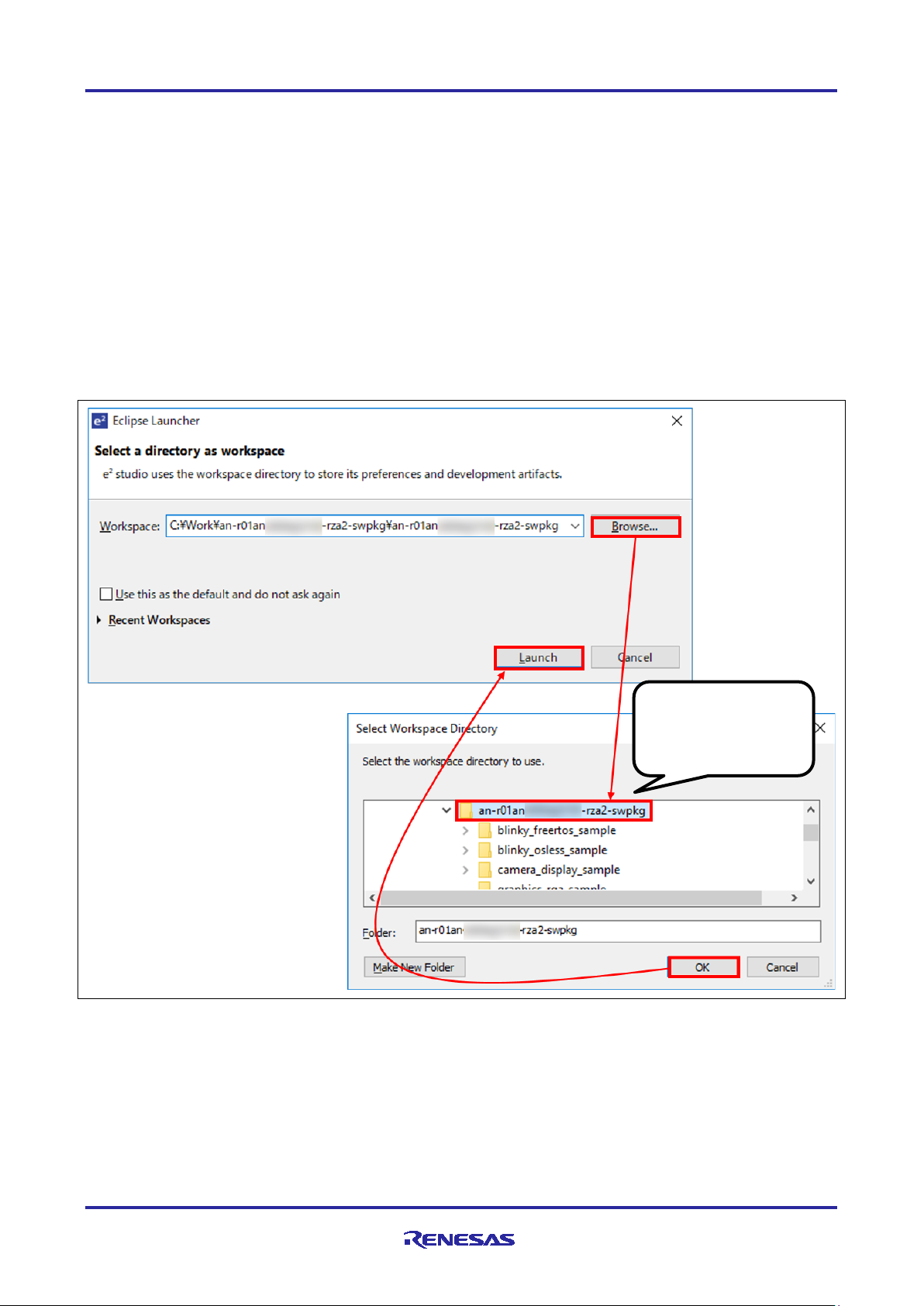
Select the top
sub-directory.
3. Trying sample application
3.1 Importing Software Package into IDE
This package is distributed as an archive file. Build project of this package can be imported into e2 studio
from the Project Import Menu. User can import the project to e
section.
Obtain the package to use.
Extract the contents of the package.
Extract the individual projects to a short path.
Launch e
2
studio from the start menu.
Set the top directory which has each sample project sub-directory for the workspace directory. These
2 steps are shown in Figure 3-1.
2
studio by the following procedure in this
directory of
each sample project
Figure 3-1 e2 studio launching
R01QS0042EJ0100 Rev.1.00 Page 4 of 24
Sep.30.20
RZ/A2M Group RZ/A2M Software Package for GR-MANGO Quick Start Guide
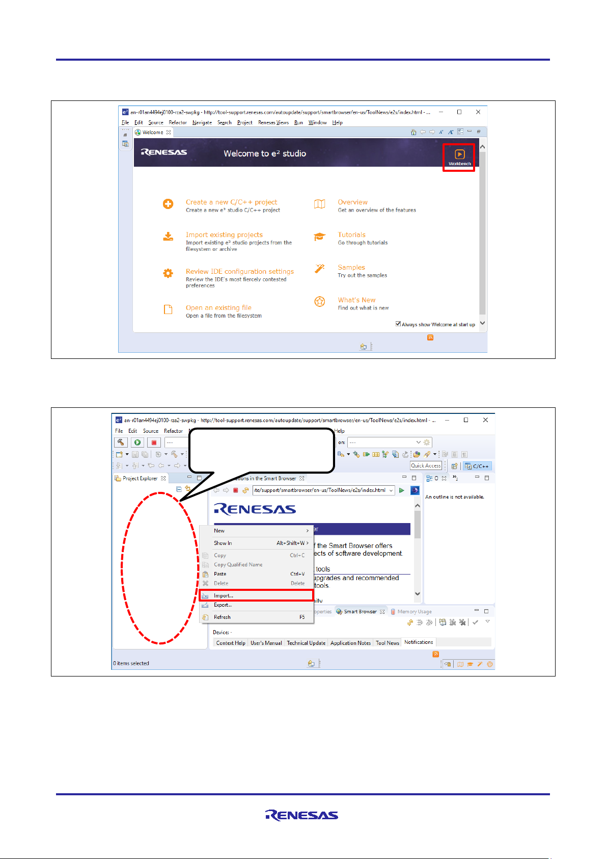
Right-click around this
In the e
2
studio welcome screen, click ‘Workbench’. This is shown in Figure 3-2.
Figure 3-2 Position of ‘Workbench’ switch
Right-click in the Project Explorer window and select ‘Import’. This is shown in Figure 3-3.
space.
R01QS0042EJ0100 Rev.1.00 Page 5 of 24
Sep.30.20
Figure 3-3 Selecting ‘Import’
RZ/A2M Group RZ/A2M Software Package for GR-MANGO Quick Start Guide
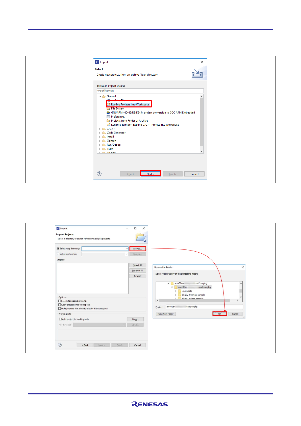
Under ‘Import’ window, select General > Existing Projects into Workspace and click ‘Next’. This is
shown in Figure 3-4.
Figure 3-4 Menu of ‘Import’ window
Select “Browse” at the right of “Select root directory:”, and “Browse for Folder” dialog box will be
appeared.
Click “OK”. These 2 steps are shown in Figure 3-5.
Figure 3-5 Select root directory
R01QS0042EJ0100 Rev.1.00 Page 6 of 24
Sep.30.20
RZ/A2M Group RZ/A2M Software Package for GR-MANGO Quick Start Guide
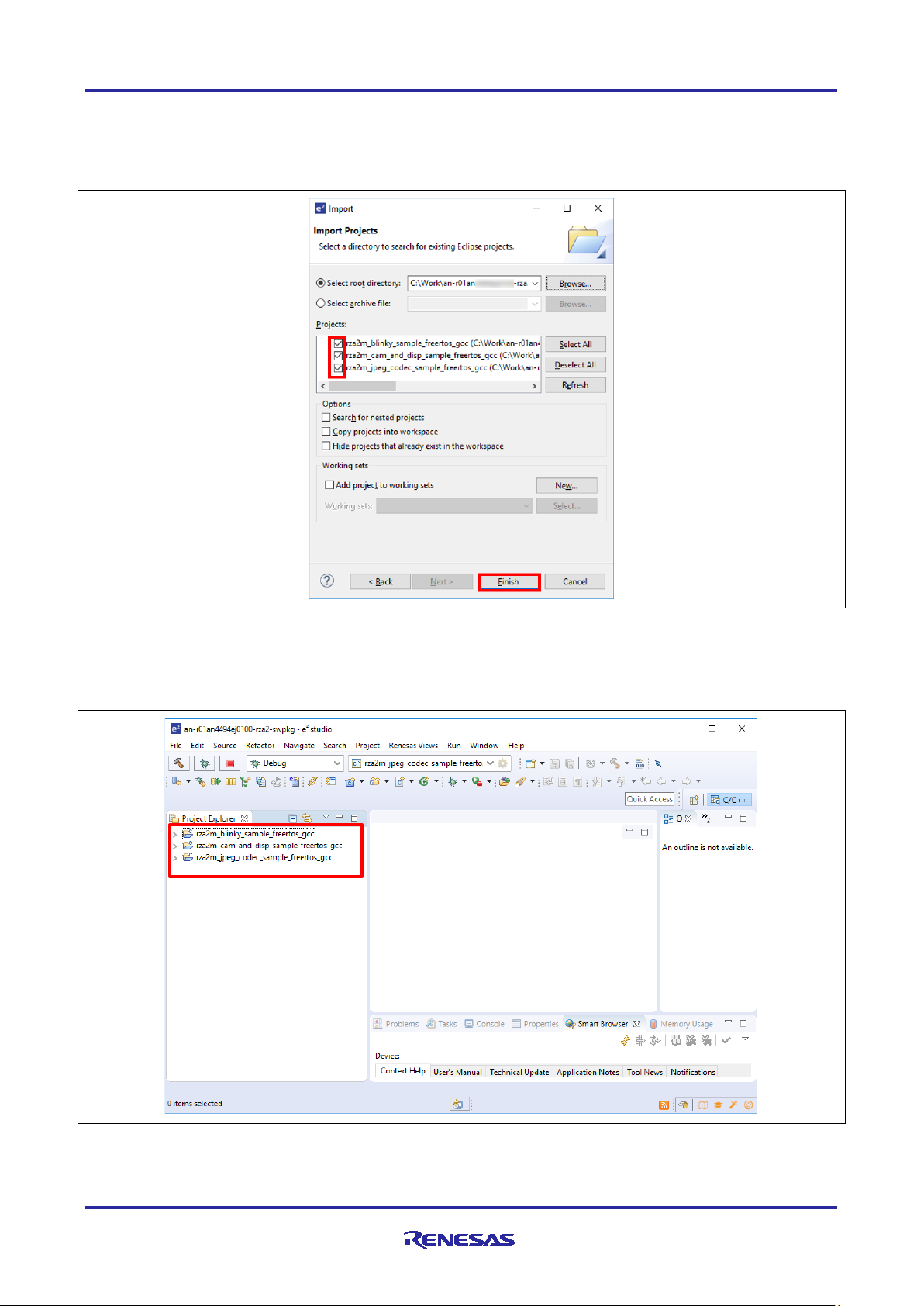
Confirm your target proj ec t is checked, then click ‘Finish’. This is shown in Figure 3-6.
(Note: Projects in Figure 3-6 are just sample. From here, please read the project name as your target
project name.)
Figure 3-6 Import target project
Now, target projects are imported, and user can see them in the Project Explorer window. This is
shown in Figure 3-7.
Figure 3-7 Confirmation on ‘Project Explorer’ window
R01QS0042EJ0100 Rev.1.00 Page 7 of 24
Sep.30.20
RZ/A2M Group RZ/A2M Software Package for GR-MANGO Quick Start Guide
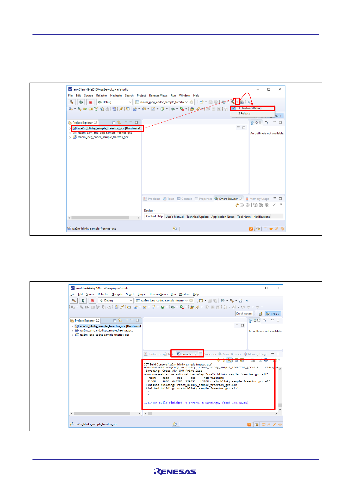
3.2 Build and Download to target board
Select your target project by left clicking on it, then click the arrow next to build button (hammer icon)
and select ‘HardwareDebug’ from the drop-down menu. From next time, user can build the project by
this Build button (hammer icon). This is shown in Figure 3-8.
Figure 3-8 Build the target project
2
e
studio tool build the project, and the build status can be confirmed in Console window
(Note: Please mind the length of your workspace path. If the path is too long, there is a possibility of
build error.) This is shown in Figure 3-9.
Figure 3-9 Confirmation build status
R01QS0042EJ0100 Rev.1.00 Page 8 of 24
Sep.30.20

RZ/A2M Group RZ/A2M Software Package for GR-MANGO Quick Start Guide
After the build is completed, the binary format file is generated in the “HardwareDebug” directory of the
target project. When connect the PC and GR-MANGO via USB cable, PC detects GR-MANGO as
MBED drive. User can download the program by drag-and-drop the program binary file to MBED drive.
Execute the program by push the reset button of GR-MANGO after download.
3.3 CMSIS-DAP based debugging
GR-MANGO supports ARM Mbed DAPLink feature and user can debug with OpenOCD.
Please refer page below to make out how to debug GR-MANGO with OpenOCD.
https://os.mbed.com/teams/Renesas/wiki/How-to-debug-with-e2-studio
R01QS0042EJ0100 Rev.1.00 Page 9 of 24
Sep.30.20

RZ/A2M Group RZ/A2M Software Package for GR-MANGO Quick Start Guide
4. Adding drivers and middleware
This section describes how to integrate drivers, middleware into the project which included in this package.
In RZ/A2M Software Package for GR-MANGO, the drivers and middleware are managed as components,
and the components can be added by e2 studio.
Refer the sample projects bundled in RZ/A2M Simple Applications Package for GR-MANGO(R01AN5595)
for examples of usage of each driver and each middleware.
Refer RZ/A2M Smart Configurator User's Guide: e² studio
e.g.) how to install drivers and middleware to e2 studio.
(R20AN0583) for the usage of Smart Configurator.
R01QS0042EJ0100 Rev.1.00 Page 10 of 24
Sep.30.20

RZ/A2M Group RZ/A2M Software Package for GR-MANGO Quick Start Guide
omponent
Explanation)
S
r_cbuffer
r_dmac
r_drp
r_octabus
r_mipi
r_ostm
r_riic
r_rvapi
r_scifa
r_sdhi_simplified
r_ssif
r_usbh0_hidc
r_usbh0_basic
r_usb1_hidc
r_usb1_basic
r_vdc
fatfs
(Ring buffer)
(DMAC driver)
(DRP driver)
(Octabus driver)
(MIPI driver)
(OS timer driver)
(RIIC driver)
(Video utility)
(SCIFa driver)
(SDHI driver)
(SSIF driver)
(USBH ch0 HID driver)
(USBH ch0 basic driver)
(USBH ch1 HID driver)
(USBH ch1 basic driver)
(VDC6 driver)
(FatFS filesystem)
simple
blinky_freertos*1
✔
- - -
- ✔ -
- ✔ - - - - - - -
-
blinky_osless*2
✔
- - -
- ✔ -
- ✔ - - - - - - -
-
cam_and_disp*3
✔
- - -
✔ ✔ ✔ ✔ ✔
- - - - -
- ✔ -
drp_basic*3
✔ - ✔ - ✔ ✔ ✔ ✔ ✔
- - - - -
- ✔ - drp_dynamic1*3
✔ - ✔ - ✔ ✔ ✔ ✔ ✔
- - - - -
- ✔ - drp_dynamic2*3
✔ - ✔ - ✔ ✔ ✔ ✔ ✔
- - - - -
- ✔ - drp_dynamic3*3
✔ - ✔ ✔ ✔ ✔ ✔ ✔ ✔
- - - - -
- ✔ -
drp_parallel*3
✔ - ✔ - ✔ ✔ ✔ ✔ ✔
- - - - -
- ✔ -
drp_simple_isp_sample1*3
✔ - ✔ - ✔ ✔ ✔ ✔ ✔
- - - - -
- ✔ - sdhi_fat*3
✔
- - -
- ✔ -
-
✔
✔
- - - - -
- ✔
ssif*3
✔
✔
- - -
✔
✔ - ✔ - ✔
- - - - - -
usbh_hid*3
✔
- - -
-
✔
✔ - ✔
-
-
✔ ✔ ✔
✔
-
-
4.1 Components and related sample projects
Following table shows the components used in each sample project:
Package C
(
ample Program
applications
Note ✔ : Component is used.
- : Component is not included.
*1 : “rza2m_blinky_sample_freertos_gcc” is the name displayed in e
*2 : “rza2m_blinky_sample_osless_gcc” is the name displayed in e
*3 : “rza2m_[SampleProgram]_sample_freertos_gcc” is the name displayed in e
R01QS0042EJ0100 Rev.1.00 Page 11 of 24
Sep.30.20
2
studio.
2
studio.
2
studio.
RZ/A2M Group RZ/A2M Software Package for GR-MANGO Quick Start Guide
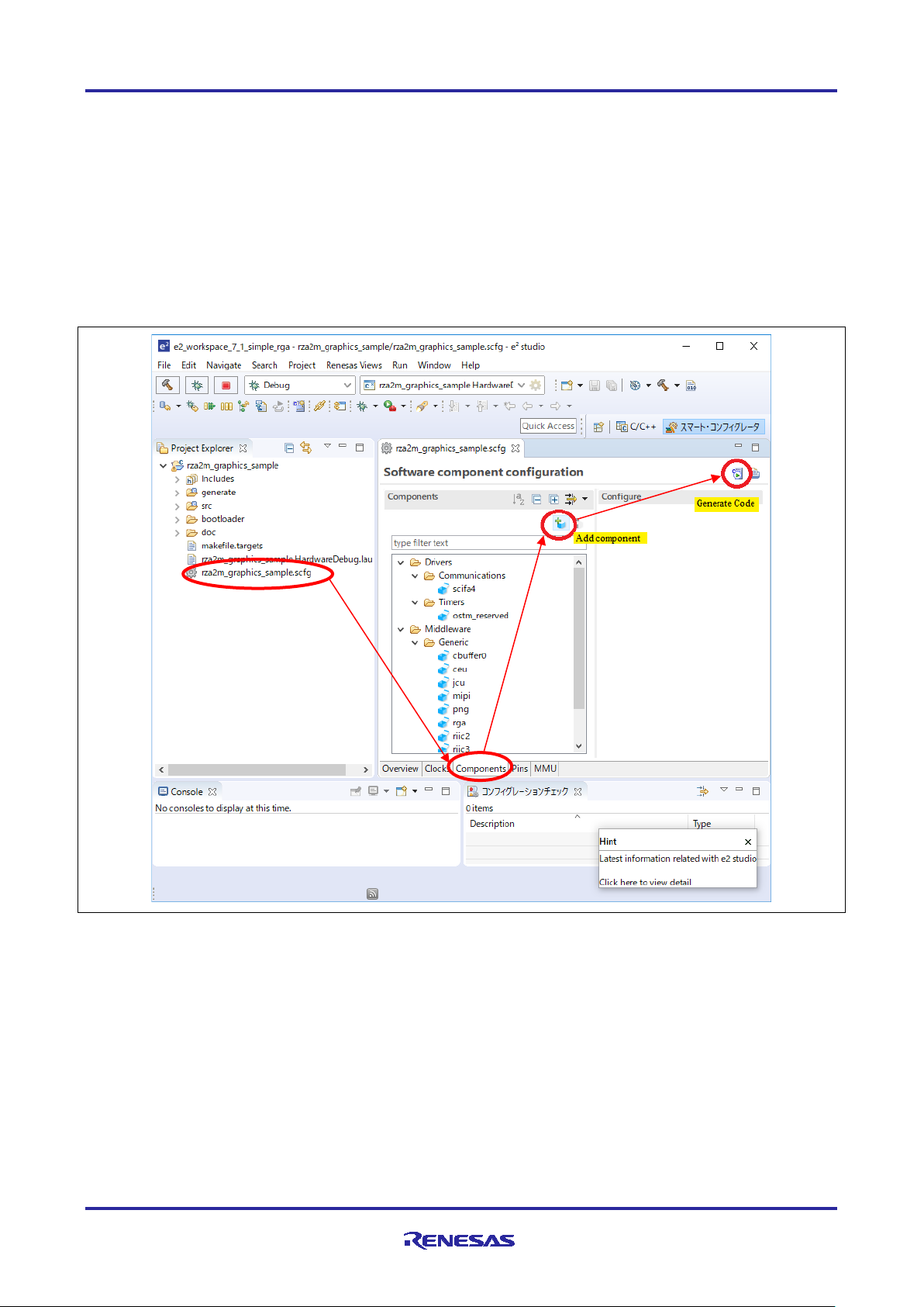
4.2 Importing Software Package into IDE
Open the project tree of target project in the Project Explorer window of e2 studio, and double
click .scfg file in the project.
Select ‘Components’ tub and add the target component from ‘Add component’ button.
After adding the target component, click ‘Generate Code’ button.
The steps above are shown in Figure 4-1.
With this, the component is added to the target project’s folder, "(Project Folder)\generate\sc_drivers" and
"(Project Folder)\.settings\smartconfigurator". After adding the component, re-build the target project
according to section 3.2.
Figure 4-1 How to add components
R01QS0042EJ0100 Rev.1.00 Page 12 of 24
Sep.30.20

RZ/A2M Group RZ/A2M Software Package for GR-MANGO Quick Start Guide
4.3 How to integrate the new component
New component is integrated to a project by the following step
Add component by the procedure shown in section 4.2.
Configure the component by Smart Configurator.
Generate the source code of the component.
Confirm API functions or the name of header file declaring API functions from the document of the
component.
Confirm the project which uses the component and use the API function name or the header file name
to find where the component is used.
Implement the source code into a project by referring the source file using the component.
R01QS0042EJ0100 Rev.1.00 Page 13 of 24
Sep.30.20

RZ/A2M Group RZ/A2M Software Package for GR-MANGO Quick Start Guide
5. FreeRTOS awareness funct i on
In this section it is shown that FreeRTOS awareness function of e2 studio.
This function supports displaying the list and the status of generated tasks, queues, and timer during break.
5.1 Adding FreeRTOS awareness function to e2 studio
5.1.1 In the case of new e2 studio installation or upgrading e2 studio
Launch e2 studio installer. If e2 studio has already been installed, select “Upgrade” or “Install”. This is
shown in Figure 5-1.
Figure 5-1 Adding FreeRTOS awareness function (new e
R01QS0042EJ0100 Rev.1.00 Page 14 of 24
Sep.30.20
2
studio installation) 1

RZ/A2M Group RZ/A2M Software Package for GR-MANGO Quick Start Guide
Check “RZ” at “Device Families” stage of install wizard. This is shown in Figure 5-2.
Figure 5-2 Adding FreeRTOS awareness function (new e
2
studio installation) 2
R01QS0042EJ0100 Rev.1.00 Page 15 of 24
Sep.30.20

RZ/A2M Group RZ/A2M Software Package for GR-MANGO Quick Start Guide
Check “RTOS” at “Extra Components” stage of install wizard. This is shown in Figure 5-3.
Figure 5-3 Adding FreeRTOS awareness function (new e
2
studio installation) 3
R01QS0042EJ0100 Rev.1.00 Page 16 of 24
Sep.30.20

RZ/A2M Group RZ/A2M Software Package for GR-MANGO Quick Start Guide
Check “GCC ARM Embedded 6 2017q2” and “LibGen for GCC ARM Embedded” at “Additional
Software” stage of install wizard. This is shown in Figure 5-4.
By setting up to here, FreeRTOS awareness function will be enabled.
Figure 5-4 Adding FreeRTOS awareness function (new e
2
studio installation) 4
R01QS0042EJ0100 Rev.1.00 Page 17 of 24
Sep.30.20
RZ/A2M Group RZ/A2M Software Package for GR-MANGO Quick Start Guide
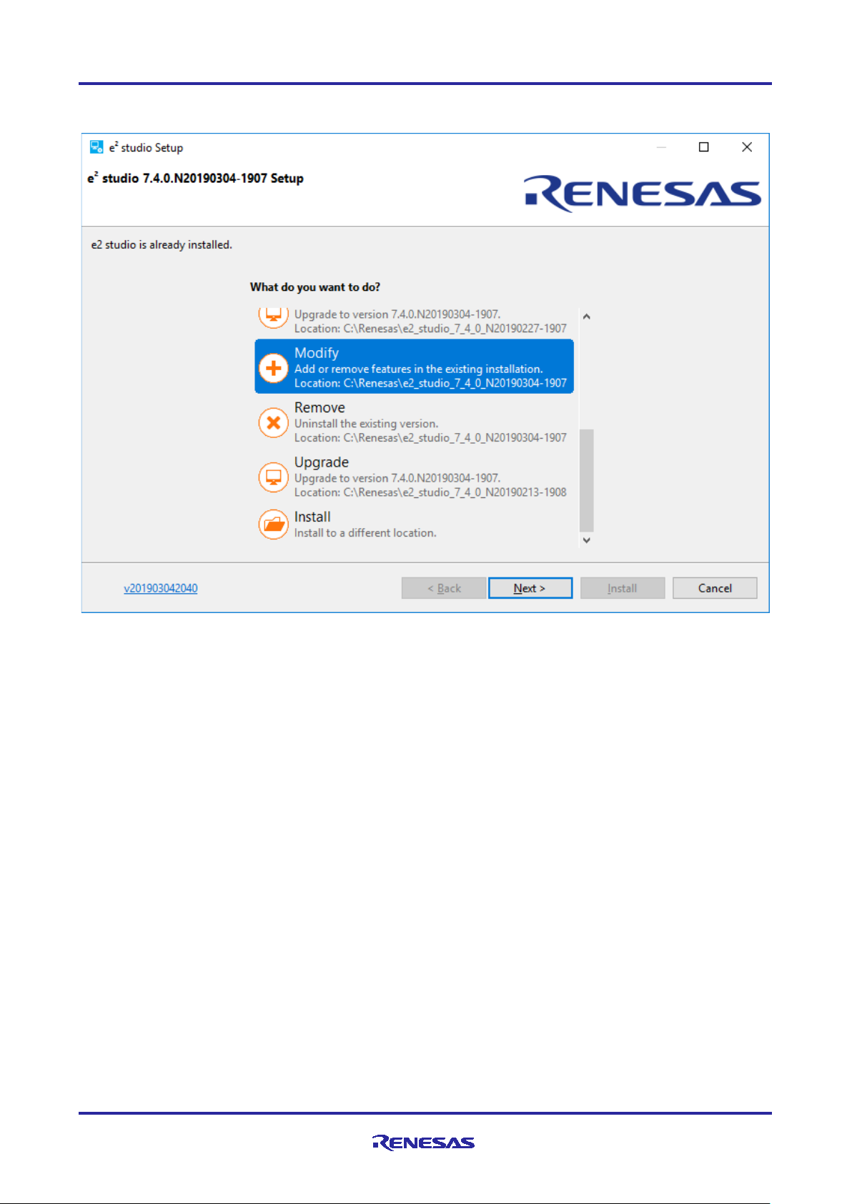
5.1.2 In the case that e2 studio has already been installed
Launch e2 studio installer. And select “Modify”. This is shown in Figure 5-5.
Figure 5-5 Adding FreeRTOS awareness function (to existing e
2
studio) 1
R01QS0042EJ0100 Rev.1.00 Page 18 of 24
Sep.30.20

RZ/A2M Group RZ/A2M Software Package for GR-MANGO Quick Start Guide
Check “Renesas RTOS Debug Views” at “Components” stage of install wizard. This is shown in Figure
5-6.
By setting up to here, FreeRTOS awareness function will be enabled.
Figure 5-6 Adding FreeRTOS awareness function (to existing e
2
studio) 2
R01QS0042EJ0100 Rev.1.00 Page 19 of 24
Sep.30.20

RZ/A2M Group RZ/A2M Software Package for GR-MANGO Quick Start Guide
5.2 How to launch FreeRTOS awareness function
1. Download the program using FreeRTOS to your board.
2. Run the downloaded program.
3. Suspend (break) the running program.
4. Select “Window” menu – “Show view” – “Other”. This is shown in Figure 5-7.
Figure 5-7 Launching FreeRTOS awareness function, step 4
R01QS0042EJ0100 Rev.1.00 Page 20 of 24
Sep.30.20

RZ/A2M Group RZ/A2M Software Package for GR-MANGO Quick Start Guide
5. Select “Queue Table” under “OpenRTOS Viewer”. And Press “Open”. This is shown in Figure 5-8.
6. After the same procedure, select “Task Table” under “OpenRTOS Viewer”. And Press “Open”.
7. After the same procedure, select “Timer Table” under “OpenRTOS Viewer”. And Press “Open”.
Figure 5-8 Launching FreeRTOS awareness function, step 5,6, and 7
R01QS0042EJ0100 Rev.1.00 Page 21 of 24
Sep.30.20

RZ/A2M Group RZ/A2M Software Package for GR-MANGO Quick Start Guide
8. Status of FreeRTOS will be shown.
Figure 5-9 shows the example of Queue Table view.
Figure 5-10 shows the example of Task Table view.
Figure 5-11 shows the example of Timer Table view.
Figure 5-9 FreeRTOS awareness function (Queue Table)
Figure 5-10 FreeRTOS awareness functi o n (T ask Table)
Figure 5-11 FreeRTOS awareness functi o n (T imer Table)
R01QS0042EJ0100 Rev.1.00 Page 22 of 24
Sep.30.20

RZ/A2M Group RZ/A2M Software Package for GR-MANGO Quick Start Guide
6. Support
Online technical support and information is available at https://www.renesas.com
Technical Contact Details
America: techsupport.america@renesas.com
Europe: https://www.renesas.com/eu/en/support/contact.html
Japan & global: https://www.renesas.com/support/contact.html
R01QS0042EJ0100 Rev.1.00 Page 23 of 24
Sep.30.20
RZ/A2M Group RZ/A2M Software Package for GR-MANGO Quick Start Guide
Rev.
Date
Description
Page
Summary
1.00
Sep. 30, 2020
―
First edition issued
Revision History
R01QS0042EJ0100 Rev.1.00 Page 24 of 24
Sep.30.20

General Precautions in the Handling of Microprocessing Unit and Microcontrolle r
Unit Products
The following usage notes are applicable to all Microprocessing unit and Microcontroller unit products from Renesas. For detailed usage no tes on th e
products covered by this document, refer to the relevant sections of the document as well as any technical updates that have been issued for the products.
1. Precaution against Electrostatic Discharge (ESD)
A strong electrical field, when exposed to a CMOS device, can cause destruction of the gate oxide and ultimately degrade the device operation. Steps
must be taken to stop the generation of static electricity as much as possible, and quickly dissipate it when it occurs. Environmental control must be
adequate. When it is dry, a humidifier should be used. This is recommended to avoid using insulators that can easily build up static electricity.
Semiconductor devices must be stored and transported in an anti-static container, static shielding bag or conductive material. All test and
measurement tools including work benches and floors must be grounded. The operator must also be grounded using a wrist strap. Semiconductor
devices must not be touched with bare hands. Similar precautions must be taken for printed circuit boards with mounted semiconductor devices.
2. Processing at power-on
The state of the product is undefined at the time when power is supplied. The states of internal circuits in the LSI are indeterminate and the states of
register settings and pins are undefined at the time when power is supplied. In a finished product where the reset signal is applied to the external reset
pin, the states of pins are not guaranteed from the time when power is supplied until the reset process is completed. In a similar way, the states of pins
in a product that is reset by an on-chip power-on reset function are not guaranteed from the time when power is supplied until the power reaches the
level at which resetting is specified.
3. Input of signal during power-off state
Do not input signals or an I/O pull-up power supply while the device is powered off. The current injection that results from input of such a signal or I/O
pull-up power supply may cause malfunction and the abnormal current that passes in the device at this time may cause degradation of internal
elements. Follow the guideline for input signal during power-off state as described in your product documentation.
4. Handling of unuse d pi ns
Handle unused pins in accordance with the directions given under handling of unused pins in the manual. The input pins of CMOS products are
generally in the high-impedance state. In operation with an unused pin in the open-circuit state, extra electromagnetic noise is induced in the vicinity of
the LSI, an associated shoot -through current flows internally, and malfunctions occur due to the false recognition of the pin state as an input signal
become possible.
5. Clock signals
After applying a reset, only release the reset line after the operating clock signal becomes stable. When switching the clock signal during program
execution, wait until the target clock signal is stabilized. When the clock signal is generated with an external resonator or from an external osci ll at or
during a reset, ensure that the reset line is only released after full stabilization of the clock signal. Additionally, when switching to a clock signal
produced with an external resonator or by an external oscillator while program execution is in progress, wait until the target clock signal is stable.
6. Voltage application waveform at input pin
Waveform distortion due to input noise or a reflected wave may cause malfunction. If the input of the CMOS device stays in the area between V
(Max.) and V
input level is fixed, and also in the transition period when the input level passes through the area between V
7. Prohibition of access to reserved addresses
Access to reserved addresses is prohibited. The reserved addresses are provided for possible future expansion of functions. Do not access these
addresses as the correct ope ration of the LSI is not guarantee d.
8. Differences between products
Before changing from one product to another, for example to a product with a different part number, confirm that the change will not lead to problems.
The characteristics of a microprocessing unit or microcontroller unit products in the same group but having a different part number might differ in terms
of internal memory capacity, layout pattern, and other factors, which can affect the ranges of electrical characteristics, such as characteristic values,
operating margins, immunity to noise, and amount of radiated noise. When changing to a product with a different part number, implement a systemevaluation test for the given product.
(Min.) due to noise, for example, the device may malfunction. Take care to prevent chattering noise from entering the device when the
IH
(Max.) and VIH (Min.).
IL
IL

Corporate Headquarters
Contact information
www.renesas.com
Trademarks
of their respective owners.
Notice
1. Descriptions of circuits, software and other related information in this document are provided only to illustrate the operation of semiconductor products
and application examples. You are fully responsible for the incorporation or any other use of the circuits, software, and information in the design of your
product or system. Renesas Electronics disclaims any and all liability for any losses and damages incurred by you or third parties arising from the use
of these circuits, software, or information.
2. Renesas Electronics hereby expressly disclaims any warranties against and liability for infringement or any other claims involving patents, copyrights,
or other intellectual property rights of third parties, by or arising from the use of Renesas Electronics products or technical information described in this
document, including but not limited to, the product data, drawings, charts, programs, algorithms, and application examples.
3. No license, express, implied or otherwise, is granted hereby under any patents, copyrights or other intellectual property rights of Renesas Electronics
or others.
4. You shall not alter, modify, copy, or reverse engineer any Renesas Electronics product, whether in whole or in part. Renesas Electronics disclaims any
and all liability for any losses or damages incurred by you or third parties arising from such alteration, modification, copying or reverse engineering.
5. Renesas Electronics products are classified according to the following two quality grades: “Standard” and “High Quality”. The intended applications for
each Renesas Electronics product depends on the product’s quality grade, as indicated below.
"Standard": Computers; office equipment; communications equipment; test and measurement equipment; audio and visual equipment; home
"High Quality": Transportation equipment (automobiles, trains, ships, etc.); traffic control (traffic lights); large-scale communication equipment; key
Unless expressly designated as a high reliability product or a product for harsh environments in a Renesas Electronics data sheet or other Renesas
Electronics document, Renesas Electronics products are not intended or authorized for use in products or systems that may pose a direct threat to
human life or bodily injury (artificial life support devices or systems; surgical implantations; etc.), or may cause serious property dama ge (sp ace
system; undersea repeaters; nuclear power control systems; aircraft control systems; key plant systems; military equipment; etc.). Renesas Electronics
disclaims any and all liability for any damages or losses incurred by you or any third parties arising from the use of any Renesas Electronics product
that is inconsistent with any Renesas Electronics data sheet, user’s manual or other Renesas Electronics document.
6. When using Renesas Electronics products, refer to the latest product information (data sheets, user’s manuals, application notes, “General Notes for
Handling and Using Semiconductor Devices” in the reliability handbook, etc.), and ensure that usage conditions are within the ranges specified by
Renesas Electronics with respect to maximum ratings, operating power supply voltage range, heat dissipation characteristics, installation, etc. Renesas
Electronics disclaims any and all liability for any malfunctions, failure or accident arising out of the use of Renesas Electronics products outs i de of s uch
specified ranges.
7. Although Renesas Electronics endeavors to improve the quality and reliability of Renesas Electronics products, semiconductor products have specific
characteristics, such as the occurrence of failure at a certain rate and malfunctions under certain use conditions. Unless designated as a high reliability
product or a product for harsh environments in a Renesas Electronics data sheet or other Renesas Electronics document, Renesas Electronics
products are not subject to radiation resistance design. You are responsible for implementing safety measures to guard against the possibility of bodily
injury, injury or damage caused by fire, and/or danger to the public in the event of a failure or malfunction of Renesas Electronics products, such as
safety design for hardware and software, including but not limited to redundancy, fire control and malfunction prevention, appropriate treatment for
aging degradation or any other appropriate measures. Because the evaluation of microcomputer software alone is very difficult and impractical, you are
responsible for evaluating the safety of the final products or systems manufactured by you.
8. Please contact a Renesas Electronics sales office for details as to environmental matters such as the environmental compatibility of each Renesas
Electronics product. You are responsible for carefully and sufficiently investigating applicable laws and regulations that regulate the inclusion or use of
controlled substances, including without limitation, the EU RoHS Directive, and using Renesas Electronics products in compliance with all these
applicable laws and regulations. Renesas Electronics disclaims any and all liability for damages or losses occurring as a result of your noncompliance
with applicable laws and regulations.
9. Renesas Electronics products and technologies shall not be used for or incorporated into any products or systems whose manufacture, use, or sale is
prohibited under any applicable domestic or foreign laws or regulations. You shall comply with any applicable export control laws and regulations
promulgated and administered by the governments of any countries asserting jurisdiction over the parties or transactions.
10. It is the responsibility of the buyer or distributor of Renesas Electronics products, or any other party who distributes, disposes of, or otherwise sells or
transfers the product to a third party, to notify such third party in advance of the contents and conditions set forth in this document.
11. This document shall not be reprinted, reproduced or duplicated in any form, in whole or in part, without prior written consent of Renesas Electronics.
12. Please contact a Renesas Electronics sales office if you have any questions regarding the information contained in this document or Renesas
Electronics products.
(Note1) “Renesas Electronics” as used in this document means Renesas Electronics Corporation and also includes its directly or indirectly controlled
(Note2) “Renesas Electronics product(s)” means any product developed or manufactured by or for Renesas Electronics.
subsidiaries.
electronic appliances; machine tools; personal electronic equipment; industrial robots; etc.
financial terminal systems; safety control equipment; etc.
(Rev.4.0-1 Novembe r 201 7)
TOYOSU FORESIA, 3-2-24 Toyosu,
Koto-ku, Tokyo 135-0061, Japan
Renesas and the Renesas logo are trademarks of Renesas Electronics
Corporation. All trademarks and registered trademarks are the property
For further information on a product, technology, the most up-to-date
version of a document, or your ne are s t sales office, please visit:
www.renesas.com/contact/
.
© 2020 Renesas Electronics Corporation. All rights reserved.
 Loading...