

Page 1
User’s Manual
R12UZ0031EJ0100 Rev.1.00 Page 1 of 29
Feb. 21, 2019
RX72T CPU Card
User’s Manual
For Your Safety
Do not fail to read this manual before using the RX72T CPU card (RTK0EMX990C00000BJ) (the product).
• Follow the indications in this manual when using the product.
• This product is the option board of "24V Motor Control Evaluation System for RX23T (RTK0EM0006S01212BJ)".
Please read "Warnings Regarding Use of the Product" of the 24V Motor Control Evaluation System for RX23T
User's Manual, and use this product.
• Keep this manual near the product so you can refer to it whenever necessary.
• Transfer or sale of the product to third parties is prohibited without written approval.
• The purchaser or importer of the product is responsible for ensuring compliance with local regulations. In addition,
the customer is responsible for ensuring that the product is handled correctly and safely, in accordance with the laws
of the customer’s country (region).
• All information contained in this manual represents information on products at the time of publication of this
manual. Please note that the product data, specification, sales offices, contents of website, address, etc., are subject
to change by Renesas Electronics Corporation without notice due to product improvements or other reasons. Please
confirm the latest information on Renesas Electronics website.
• The manual for the product, and specification (the documents) are the tool that was developed for the function and
performance evaluation of Renesas Electronics semiconductor device (Renesas Electronics device) mounted on the
product, and not guarantee the same quality, function and performance.
• By purchasing the product or downloading the documents from Renesas Electronics website, the support services
provided from Renesas Electronics is not guaranteed.
Meaning of Notations
In this manual items related to the safe use of the product are indicated as described below.
The degree of injury to persons or damage to property that could result if the designated content in this manual is not
followed is indicated as follows.
Danger
Indicates content that, if not followed, could result in death or serious injury*1
to the user, and which is highly urgent.
Warning
Indicates content that, if not followed, could result in death or serious injury to
the user.
Caution
Indicates content that, if not followed, could result in injury*2 to persons or
physical damage.*3
Note 1. Serious injury refers to conditions resulting in persistent after-effects and for which treatment would
necessitate hospitalization or regular hospital visits, such as loss or impairment of eyesight, burns
(high- or low-temperature), electric shock, bone fracture, or poisoning.
Note 2. Injury refers to conditions for which treatment would necessitate hospitalization or regular hospital
visits.
Note 3. Physical damage refers to damage affecting the wider surroundings, such as the user’s home or
property.
R12UZ0031EJ0100
Rev.1.00
Feb. 21, 2019
Page 2
RX72T CPU Card User’s Manual
R12UZ0031EJ0100 Rev.1.00 Page 2 of 29
Feb. 21, 2019
Requirements related to the handling of the product are classified into the following categories.
• Marks indicating that an action is prohibited.
General Prohibition
The indicated action is prohibited.
Example: Do Not Touch!
Touching the specified location could
result in injury.
• Marks indicating that an action is prohibited.
General Caution
Indicates a general need for caution
that is not specified.
Example: Caution – Hot!
Indicates the possibility of injury due to
high temperature.
• Marks directing that the specified action is required.
General Instruction
The specified action is required.
Example: Turn Off (Disconnect) Power
Supply!
Instructs the user to turn off (disconnect)
the power supply to the product.
Warnings Regarding Use of the Product
◼ Danger Items
Danger
• The product should be used only by persons (users) having a thorough knowledge of
electrical and mechanical components and systems, a full knowledge of the risks
associated with handling them, and training in inverter motor control and handling motors,
or equivalent skills. Users should be limited to persons who have carefully read the Caution
Items contained in this manual.
• Unlike typical equipment, the product has no protective case to ensure safety, and it
contains moving parts and high-temperature components that could be dangerous. Do not
touch the evaluation board or cables while power is being supplied.
• Carefully check to make sure that there are no pieces of conductive materials or dust
adhering to the board, connectors, and cables.
• There are moving parts, driven by a motor. Do not touch the motor while power is being
supplied.
• Ensure that the motor is insulated and placed in a stable location before supplying power.
Do Not Connect Load to Motor!
• This could cause fire, burns, or injury.
Page 3
RX72T CPU Card User’s Manual
R12UZ0031EJ0100 Rev.1.00 Page 3 of 29
Feb. 21, 2019
◼ Warning Items
Warning
Caution – Rotating Parts!
• The system includes a motor. Touching the rotating shaft could cause high-temperature
burns or injury.
Always insert plugs, connectors, and cables securely, and confirm that they are fully inserted.
• Incomplete connections could cause fire, burns, electric shock, or injury.
Use the power supply apparatus specified in the manual.
• Failure to do so could cause fire, burns, electric shock, injury, or malfunction.
Disconnect the power supply and unplug all cables when the system will not be used for a
period of time or when moving the system.
• Failure to do so could cause fire, burns, electric shock, or malfunction.
• This will protect the system against damage due to lightning.
Use a mechanism (switch, outlet, etc.) located within reach to turn off (disconnect) the power
supply.
• In case of emergency, it may be necessary to cut off the power supply quickly.
Turn off the power supply immediately if you notice abnormal odor, smoke, abnormal sound,
or overheating.
• Continuing to use the system in an abnormal condition could cause fire, burns, or electric
shock.
Do Not Disassemble, Modify, or Repair!
• Doing so could cause fire, burns, electric shock, injury, or malfunction.
Do not use the product for any purpose other than initial evaluation of motor control in a testing
room or lab. Do not integrate the product or any part of it into other equipment. Do not insert or
remove cables or connectors when the product is powered on.
• The product has no safety case.
• Failure to observe the above could cause fire, electric shock, burns, or malfunction.
• The product may not perform as expected if used for other than its intended purpose.
◼ Caution Items
Caution
Caution – Hot!
• The motor gets hot. Touching it could cause high-temperature burns.
Follow the procedure specified in the manual when powering the system on or off.
• Failure to do so could cause overheating or malfunction.
Caution – Static Electricity
• Use the antistatic band. Failure to do so could cause malfunction or unstable motion.
Page 4
RX72T CPU Card User’s Manual
R12UZ0031EJ0100 Rev.1.00 Page 4 of 29
Feb. 21, 2019
Overview
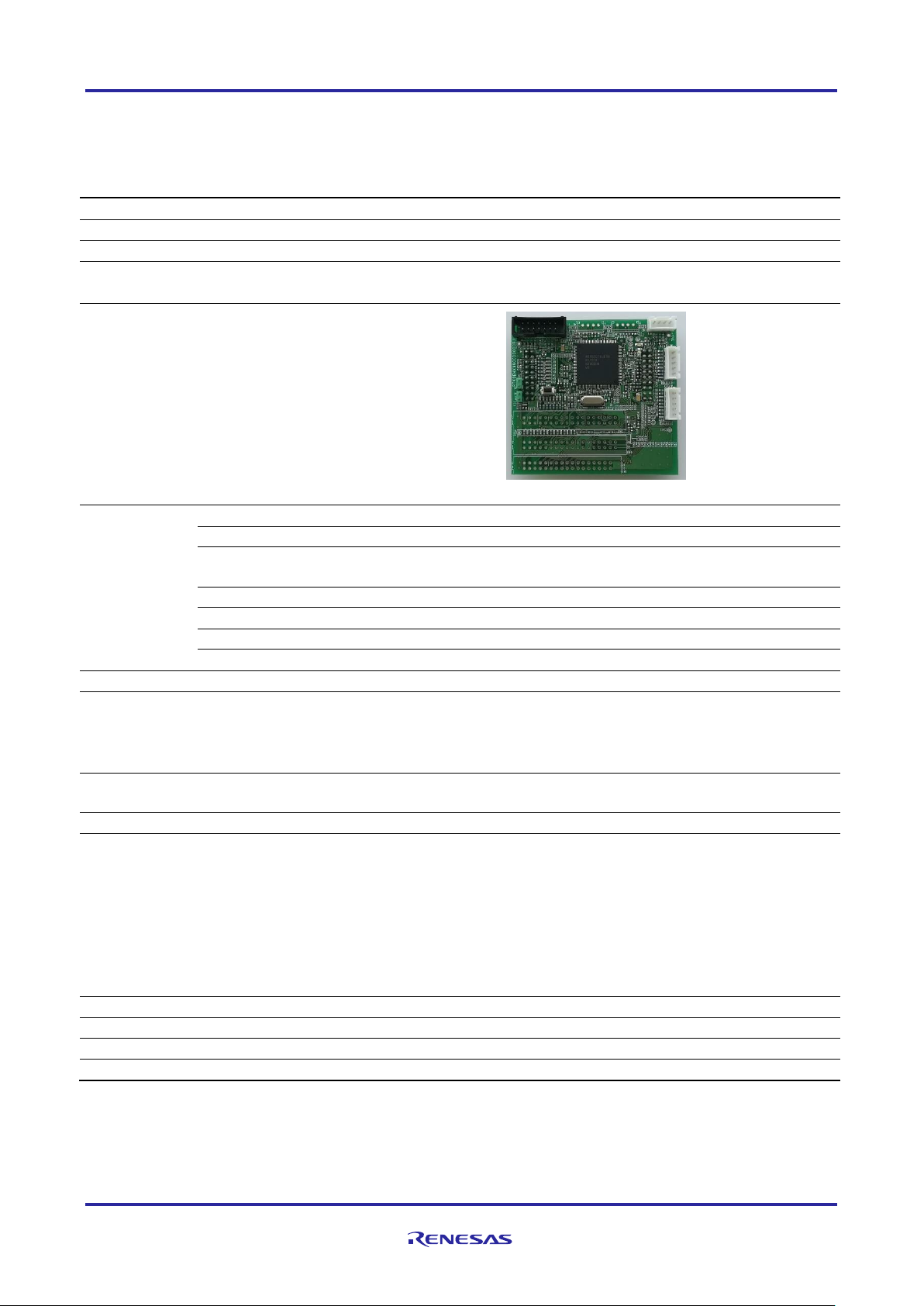
The RX72T CPU card (RTK0EMX990C00000BJ) is an optional board for use with the 24V Motor Control Evaluation
System for RX23T (RTK0EM0006S01212BJ) (the Motor RSSK). The Motor RSSK comprises a 24V system inverter
board (RTK0EM0001B00012BJ) (the INV-BRD) and a RX23T CPU card (RTK0EM0013C01201BJ) (the RX23TCRD). By replacing the RX23T-CRD with the product, motor evaluation can be performed using the RX72T.
An emulator and equipment related to the Motor RSSK must be provided by the customer.
This user’s manual describes the proper handling of the product. Content related to the product is presented in chapters
0 to 4 and 6 to 8. Content related to connection of the INV-BRD supplied with the Motor RSSK is presented in chapter
5. For details of the operation of the INV-BRD, refer to the Motor RSSK user’s manual (R20UT3697EJ).
Target Device
RX72T microcontroller
Related Documents
• RX72T CPU Card Schematic : R12TU0057EJ
• RX72T CPU Card BOM List : R12TU0058EJ
• RX72T CPU Card PWB Pattern Drawing : R12TU0059EJ
• Renesas Solution Starter Kit
24V Motor Control Evaluation System for RX23T (Motor RSSK) User’s Manual: R20UT3697EJ
Package Contents
• RX72T CPU Card Information
• Caution regarding the Motor Control Evaluation Board – RX72T CPU Card -
Abbreviations
Abbreviations
Full Name
Remarks
Motor RSSK
24V Motor Control Evaluation System for
RX23T
Motor control evaluation kit for RX23T
Product No.: RTK0EM0006S01212BJ
INV-BRD
24V Inverter Board
Inverter board supplied with motor control
evaluation kit for RX23T
Product No.: RTK0EM0001B00012BJ
RX23T-CRD
RX23T CPU Card
RX23T CPU card supplied with motor
control evaluation kit for RX23T
Product No.: RTK0EM0013C01201BJ
E1
E1 emulator
on-chip debugging emulator and flash
programmer
Product No.: R0E000010KCE00
E2 Lite
E2 emulator Lite
on-chip debugging emulator and flash
programmer
Product No.: RTE0T0002LKCE00000R
Page 5

RX72T CPU Card User’s Manual
R12UZ0031EJ0100 Rev.1.00 Page 5 of 29
Feb. 21, 2019
Contents
1. Features .......................................................................................................................... 6
2. Specifications ................................................................................................................. 7
2.1 Specification ................................................................................................................................ 7
2.2 Regulatory Compliance Notices ................................................................................................ 8
2.2.1 European Union regulatory notices .................................................................................... 8
3. Block Diagram ................................................................................................................ 9
4. Layout ........................................................................................................................... 10
5. Usage ............................................................................................................................ 11
5.1 Quick Start ................................................................................................................................. 11
5.1.1 Preparation .......................................................................................................................... 11
5.1.2 Replacing the CPU card ..................................................................................................... 11
5.1.3 Preparation for Operation Test .......................................................................................... 11
5.1.4 Operation Test ..................................................................................................................... 11
5.1.5 Finishing the Operation Test ............................................................................................. 11
5.2 Operation ................................................................................................................................... 12
5.2.1 Basic Operation................................................................................................................... 12
5.2.2 Canceling an Error State .................................................................................................... 12
5.3 In Case of Abnormal Odor, Smoke, Abnormal Sound, Overheating, Etc. ........................... 12
6. Functions ...................................................................................................................... 13
6.1 Power Supply............................................................................................................................. 13
6.2 Connecting the Emulator ......................................................................................................... 13
6.3 Connecting the Inverter Board ................................................................................................ 14
6.4 Connecting the Serial Communication ................................................................................... 15
6.5 Hall Sensor Signal Input ........................................................................................................... 15
6.6 Encoder Signal Input ................................................................................................................ 16
6.7 Connecting the Extender Board .............................................................................................. 17
6.8 Extension of Unused Pins ........................................................................................................ 19
6.9 Reset Circuit .............................................................................................................................. 20
6.10 Crystal Resonator ..................................................................................................................... 20
6.11 LEDs ........................................................................................................................................... 20
6.12 JP1, JP2 ...................................................................................................................................... 20
7. Details of RX72T CPU Card .......................................................................................... 21
7.1 RX72T Features ......................................................................................................................... 21
7.2 RX72T Pin Assignments ........................................................................................................... 22
7.3 List of RX72T Pin Functions .................................................................................................... 23
8. Caution Items................................................................................................................ 28
Page 6

RX72T CPU Card User’s Manual
R12UZ0031EJ0100 Rev.1.00 Page 6 of 29
Feb. 21, 2019
1. Features
1. Populated with RX72T 32-bit microcontroller suitable for inverter control.
2. CPU card designed specifically for use with INV-BRD supplied with Motor RSSK.
3. Supports writing of software to flash memory using the E1 or E2 Lite.
4. Equipped with Hall sensor input connector and encoder input connector.
5. Equipped with serial communication connector.
Page 7
RX72T CPU Card User’s Manual
R12UZ0031EJ0100 Rev.1.00 Page 7 of 29
Feb. 21, 2019
2. Specifications
2.1 Specification
Table 2-1 Overview of RX72T CPU Card Specifications
Item
Specification
Product name
RX72T CPU card
Board product No.
RTK0EMX990C00000BJ
Supported inverter board
/ product No.
Supplied with 24V Motor Control Evaluation System for RX23T
24V Inverter Board / RTK0EM0001B00012BJ
Exterior view
Note: Appearance of actual product may differ from photo.
MCU
Product group
RX72T group
Product No.
R5F572TKCDFB
CPU max.
operating frequency
200 MHz
Bit count
32 bits
Package / Pin count
LFQFP / 144 pins
ROM
1MB
RAM
128KB
MCU input clock
10MHz
Input power supply voltage
DC 5 V (±5%) *1
Selectable among the following:
• Power supply from supported inverter board
• Power supply from E1, E2 Lite *2
Supported sensors
Hall sensor, encoder
(through holes provided for signal monitoring test pins)
Supported emulator
E1, E2 Lite
Connectors
• Inverter board connectors x 2
• Extender board connector x 2 (Unmounted)
• SCI communication connectors x 3 (Two of them are unmounted)
• CAN communication connector (Shared with SCI connector,
unmounted)
• Emulator connector
• Hall sensor signal input connector
• Encoder signal input connector
Switch
MCU external reset switch
LEDs
User control LEDs x 2
Operating temperature
Room temperature
Operating humidity
No condensation
Note 1. Supply voltage is DC 3.3V from E2 Lite.
Note 2. Power supply from E1 or E2 Lite is not supported when INV-BRD is connected.
Page 8
RX72T CPU Card User’s Manual
R12UZ0031EJ0100 Rev.1.00 Page 8 of 29
Feb. 21, 2019
2.2 Regulatory Compliance Notices
2.2.1 European Union regulatory notices
This product complies with the following EU Directives. (These directives are only valid in the European Union.)
CE Certifications:
・Electromagnetic Compatibility (EMC) Directive 2014/30/EU
EN61326-1 : 2013 Class A
WARNING: This is a Class A product. This equipment can cause radio frequency noise when used
in the residential area. In such cases, the user/operator of the equipment may be
required to take appropriate countermeasures under his responsibility.
・Information for traceability
・Authorised representative
Name: Renesas Electronics Corporation
Address: Toyosu Foresia, 3-2-24, Toyosu, Koto-ku, Tokyo 135-0061, Japan
・Manufacturer
Name: Renesas Electronics Corporation
Address: Toyosu Foresia, 3-2-24, Toyosu, Koto-ku, Tokyo 135-0061, Japan
・Person responsible for placing on the market
Name: Renesas Electronics Europe GmbH
Address: Arcadiastrasse 10, 40472 Dusseldorf, Germany
・Trademark and Type name
Trademark: Renesas
Product name: RX72T CPU Card for Motor Control
Type name: RTK0EMX990C00000BJ
Environmental Compliance and Certifications:
・Waste Electrical and Electronic Equipment (WEEE) Directive 2012/19/EU
Page 9
RX72T CPU Card User’s Manual
R12UZ0031EJ0100 Rev.1.00 Page 9 of 29
Feb. 21, 2019
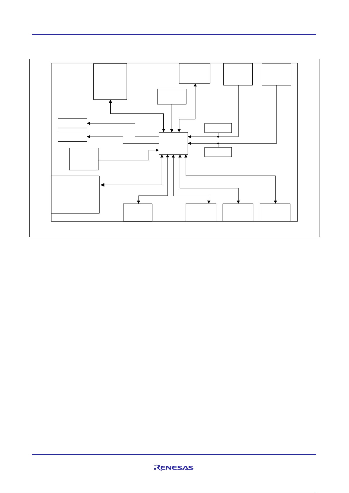
3. Block Diagram
CPU Card
SCI6
Connector
Connector
Encoder
Input
connector
Reset
Switch
Crystal
Oscillator
LED1
Hall
Input
connector
Test pin
Universal
Space
SCI5
Connector
SCI8
Connector
LED2
Inverter
Board
Connector
20pin×2
Test pin
10 MHz
Hall signal
×3
Encoder signal
×3
TXD6/RXD6
Reset signal
TXD5/RXD5
Signal
× 24
Signal
Voltage ,etc
Low active
Low active
Motor
Extender Board
x 2Connector
Signal
Voltage ,etc
RX72T
TXD8/RXD8
Emulator
Signal
Emulator
DNF
Figure 3.1 RX72T CPU Card Block Diagram
Page 10
RX72T CPU Card User’s Manual
R12UZ0031EJ0100 Rev.1.00 Page 10 of 29
Feb. 21, 2019
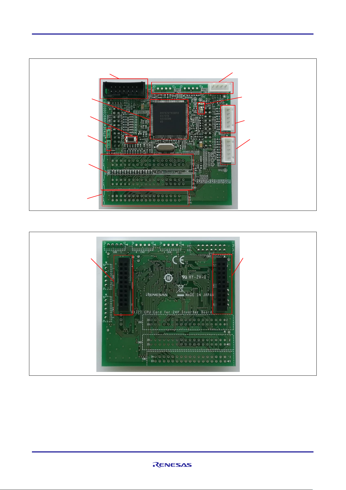
4. Layout
Serial communication connector
(CN2,CN4,CN6)
Hall sensor signal input
connector (CN5)
Encoder signal input
connector(CN3)
LEDs
(LED1,LED2)
Emulator connector
(CN7)
RX72T
Jumper
(JP1,JP2)
Reset switch
(SW1)
Expansion board
connector
(CNC,CND)
Universal area
through holes (CN1)
Figure 4.1 RX72T CPU Card Layout (Top View)
Inverter board
connector (CNA)
Inverter board
connector(CNB)
Figure 4.2 RX72T CPU Card Layout (Bottom View)
Page 11

RX72T CPU Card User’s Manual
R12UZ0031EJ0100 Rev.1.00 Page 11 of 29
Feb. 21, 2019
5. Usage
5.1 Quick Start
5.1.1 Preparation
Obtain the Motor RSSK, and perform the steps described in 5.1.1 and 5.1.2, Quick Start, of the user’s manual.
(R20UT3697EJ).
5.1.2 Replacing the CPU card
Confirm that the INV-BRD is powered off, remove the RX23T-CRD from the INV-BRD, and connect the product in its
place.
(1) Remove RX23T-CRD
(2) Make sure the inverter board
connectors are correctly aligned,
and attach RX72T CPU card
INV-BRD
RX23T-CRD
RX72T CPU card
Figure 5.1 CPU card replacement
5.1.3 Preparation for Operation Test
Perform the steps described in 5.1.3 to 5.1.5 of the Motor RSSK user’s manual (R20UT3697EJ) to prepare for motor
drive.
5.1.4 Operation Test
Perform the steps described in 5.1.6 to 5.1.9 of the Motor RSSK user’s manual (R20UT3697EJ) in the order indicated,
turn on the power supply, enable motor rotation, change the motor rotation speed, and stop motor rotation.
5.1.5 Finishing the Operation Test
After the operation test is finished, confirm that the motor shaft is no longer rotating and turn off the stabilized power
supply output.
Page 12

RX72T CPU Card User’s Manual
R12UZ0031EJ0100 Rev.1.00 Page 12 of 29
Feb. 21, 2019
5.2 Operation
5.2.1 Basic Operation
Out of the box the product is programmed with sensor-less vector control software for the RX72T. Table 5-1 lists the
software specifications and the basic operations when connected to the INV-BRD.
Table 5-1 Initial Software Specifications
Item
Specification
Control method
Sensorless vector control
VR1
Clockwise turn: Motor shaft rotates clockwise.
Counterclockwise turn: Motor shaft rotates counterclockwise.
SW1
ON: Motor rotation enabled
OFF: Motor rotation disabled
SW2
Cancels error state: OFF → ON → OFF after an error:
LED1
ON: SW1 ON and normal state.
OFF: SW1 OFF or error state.
LED2
ON: error state.
OFF: normal state.
5.2.2 Canceling an Error State
If an error occurs, LED2 lights on the INV-BRD and the product, and motor rotation stops. To recover, it is necessary to
turn off toggle switch SW1 and turn on toggle switch SW2 on the INV-BRD, and then turn off toggle switch SW2 again.
5.3 In Case of Abnormal Odor, Smoke, Abnormal Sound, Overheating, Etc.
The INV-BRD is equipped with a toggle switch (S1) to cut off the flow of current to the inverter. If an abnormal
condition (such as abnormal odor, smoke, abnormal sound, or overheating) occurs, turn off S1 to cut off current flow to
the inverter.
OFF
S1
INV-BRD
RX72T CPU Card
Figure 5.2 Cut off current
Page 13

RX72T CPU Card User’s Manual
R12UZ0031EJ0100 Rev.1.00 Page 13 of 29
Feb. 21, 2019
6. Functions
6.1 Power Supply
The product does not have a dedicated power supply connector. When connected to the INV-BRD it draws power via
the connector. When not connected to the INV-BRD, it can draw power via the Emulator connector. The product is not
allowed to draw power via the Emulator connector when it is connected to the INV-BRD.
6.2 Connecting the Emulator
The E1/E2 Lite on-chip debugging emulator from Renesas Electronics is used to write software (program) to the flash
memory of the RX72T. Software will be downloaded into the product via E1 or E2 Lite. It is also necessary to make the
settings shown in Table 6-1 in the integrated development environment to enable the emulator to supply power to the
product. Table 6-2 lists the pin assignments of the Emulator connector.
Table 6-1 E1, E2 Lite Power Supply Settings
Connection to INV-BRD
Power Supply Setting of E1, E2 Emulator
Connected
Power supply is not allowed*1
Not connected
5.0V or 3.3V power supply
Note 1. When connected to the INV-BRD, the product must draw power from the INV-BRD.
Table 6-2 Pin Assignments of Emulator Connector (CN7)
Pin No.
Pin Function
RX72T
Connection Pins
Pin No.
Pin Function
RX72T
Connection Pins
1
TCK/FINEC
TCK/FINEC
2
GND
VSS/AVSS
3
TRST#
TRST#
4
EMLE
EMLE
5
TXD1/TDO
PD3/TDO/TXD1
6
NC
-
7
MD/FINED
MD/FINED
8
VCC
VCC
9
TMS
TMS
10
UB
UB
11
TDI/RXD1
PD5/TDI/RXD1
12
GND
VSS/AVSS
13
RESET#
RES#
14
GND
VSS/AVSS
Note: See a supplement to the E1/E20/E2 emulator, E2 emulator Lite user’s manual.
Page 14

RX72T CPU Card User’s Manual
R12UZ0031EJ0100 Rev.1.00 Page 14 of 29
Feb. 21, 2019
6.3 Connecting the Inverter Board
The product connects to the INV-BRD via the inverter board connectors (CNA and CNB). Table 6-3 and Table 6-4 list
the pin assignments of the inverter board connectors.
Table 6-3 Pin Assignments of Inverter Board Connector (CNA)
Pin No.
Pin Function
RX72T
Connection Pins
Pin No.
Pin Function
RX72T
Connection Pins
1
LED1#_1
PC5
2
LED2#_1
PC6
3
LED3#_1
P34
4
NC
PA1(unused)
5
FO#
P70/POE0#
6
NC
-
7
WN
P76/MTIOC4D
8
VN_1
P75/MTIOC4C
9
UN
P74/MTIOC3D
10
WP_1
P73/MTIOC4B
11
VP
P72/MTIOC4A
12
UP_1
P71/MTIOC3B
13
SW1#_1
P35
14
SW2#_1
PA0
15
5V
VCC
16
5V
VCC
17
GND
VSS
18
GND
VSS
19
3.3V
-
20
3.3V
-
Table 6-4 Pin Assignments of Inverter Board Connector (CNB)
Pin No.
Pin Function
RX72T
Connection Pins
Pin No.
Pin Function
RX72T
Connection Pins
1
AVCC
AVCC
2
AVCC
AVCC
3
NC - 4
PGAVSS_1
PGAVSS0
5
IU_1
P40/AN000
6
IV_1
P41/AN001
7
IW_1
P42/AN002
8
VPN_1
P63/AN209
9
TEMP_1
-
10
VU_1
P60/AN206
11
VV_1
P61/AN207
12
VW_1
P62/AN208
13
VAC_1
-
14
IPFC_1
-
15
VR_1
P43/AN003
16
VN_1
-
17
VCCIO
VCC
18
VCCIO
VCC
19
GND
VSS
20
GND
VSS
Page 15
RX72T CPU Card User’s Manual
R12UZ0031EJ0100 Rev.1.00 Page 15 of 29
Feb. 21, 2019
6.4 Connecting the Serial Communication
The product communicates with the UART via the serial communication connectors. There are three serial
communication connectors: CN4, CN6, and CN7. Table 6-5 lists their pin assignments. Use CN6 when using a tool
such as waveform display in conjunction with the INV-BRD.
Table 6-5 Pin Assignments of Serial Communication Connectors (CN2, CN4, CN6)
Connector No.
Pin No.
Pin Function
RX72T Connection Pins
CN2
SCI5
(DNF)
1
5V
VCC
2
RX72T transmit side
PB5/TXD5/CTX0
3
RX72T receive side
PB6/RXD5/CRX0
4
GND
VSS
CN4
SCI8
(DNF)
1
5V
VCC
2
RX72T transmit side
PC1/ TXD8
3
RX72T receive side
PC0/ RXD8
4
GND
VSS
CN6
SCI6
1
5V
VCC
2
RX72T transmit side
PB0/TXD6
3
RX72T receive side
PB1/RXD6
4
GND
VSS
6.5 Hall Sensor Signal Input
The product is equipped with a Hall sensor signal input connector. Using this connector, it is possible to input the Hall
sensor signal from the motor supplied with the Motor RSSK directly to the product. The signal input to the product is
pulled up to 5 V and passed through an RC filter before being input to the RX72T. Table 6-6 lists the pin assignments
of the Hall sensor signal input connector, and Table 6-7 lists connector information.
Table 6-6 Pin Assignments of Hall Sensor Signal Input Connector (CN5)
Pin No.
Pin Function
RX72T Connection Pins
1
5V
VCC
2
GND
VSS
3
HALL_U_1
P23/IRQ11
4
HALL_V_1
P24/IRQ4
5
HALL_W_1
P25/IRQ10
Table 6-7 Hall Sensor Signal Input Connector Information
Part
Product No.
Manufacturer
Connector (CN5)
B5B-XH-A
J.S.T. Mfg. Co. Ltd.
Page 16
RX72T CPU Card User’s Manual
R12UZ0031EJ0100 Rev.1.00 Page 16 of 29
Feb. 21, 2019
6.6 Encoder Signal Input
The product is equipped with an encoder signal input connector. This makes it possible to input the encoder signal to
the RX72T. The signal input to the product is pulled up to 5 V and passed through an RC filter before being input to the
RX72T. Table 6-8 lists the pin assignments of the signal input connector, and Table 6-9 lists connector information.
Table 6-8 Pin Assignments of Encoder Signal Input Connector (CN3)
Pin No.
Pin Function
RX72T Connection Pins
1
5V
VCC
2
GND
VSS
3
ENC_A_1
PA7
4
ENC_B_1
PA6
5
ENC_Z_1
PA5
Table 6-9 Encoder Signal Input Connector Information
Part
Product No.
Manufacturer
Connector (CN3)
B5B-XH-A
J.S.T. Mfg. Co. Ltd.
Page 17

RX72T CPU Card User’s Manual
R12UZ0031EJ0100 Rev.1.00 Page 17 of 29
Feb. 21, 2019
6.7 Connecting the Extender Board
This product is equipped with two Extender board Connector. This connector can connect Extender Board
(RTK0EM0000Z02000BJ) via the cable. This makes it possible to control three INV-BRDs. In other words, this
product can drive three motors. Table 6-10 lists the pin assignments of the 2nd Extender board Connector.
Table 6-11 lists the pin assignments of the 3rd Extender board Connector. Note that the pin assignments of CND are
different from those of CNC and that some pins of CND are pull-upped because of sharing the pins with CN7.
Table. 6-10 Pin Assignments of 2nd Extender boards Connector
CNC
Pin No.
CNC
Pin Function
RX72T
Connection Pins
CNC
Pin No.
CNC
Pin Function
RX72T
Connection Pins
1
PGAVSS_2
PGAVSS1
2
VPN_2
P55/AN203
3
IU_2
P44/AN100
4
IV_2
P45/AN101
5
IW_2
P46/AN102
6
TEMP_2
-
7
VU_2
P52/AN200
8
VV_2
P53/AN201
9
VW_2
P54/AN202
10
VR_2
-
11
GND
VSS
12
GND
AVSS
13
LED1#_2
P15
14
LED2#_2
P16
15
LED3#_2
P17
16
FO#_2
P01/POE12#
17
WN_2
P90/MTIOC7D
18
VN_2
P91/MTIOC7C
19
UN_2
P92/MTIOC6D
20
WP_2
P93/MTIOC7B
21
VP_2
P94/MTIOC7A
22
UP_2
P95/MTIOC6B
23
SW1#_2
P13
24
SW2#_2
P14
25
GND
VSS
26
GND
VSS
27
ENC_A_2
P31/MTCLKC
28
ENC_B_2
P30/MTCLKD
29
ENC_Z_2
PA3/MTIOC2A
30
GND
VSS
31
GND
VSS
32
HALL_U_2
PE5/IRQ0
33
HALL_V_2
PE6/IRQ3
34
HALL_W_2
P12/IRQ9
35
VRL_2
P10(DNF)
36
NC
-
Page 18

RX72T CPU Card User’s Manual
R12UZ0031EJ0100 Rev.1.00 Page 18 of 29
Feb. 21, 2019
Table 6. 6-11 Pin Assignments of 3rd Extender boards Connector
CND
Pin No.
CND
Pin Function
RX72T
Connection Pins
CND
Pin No.
CND
Pin Function
RX72T
Connection Pins
1
PGAVSS_3
- 2 VPN_3
PH2/AN005
3
IU_3
PH1/AN004
4
IV_3
P47/AN103
5
IW_3
P50/AN204
6
TEMP_3
- 7 VU_3
PH5/AN104
8
VV_3
PH6/AN105
9
VW_3
PH7/AN106
10
VR_3
-
11
GND
VSS
12
GND
AVSS
13
LED1#_3
PF3
14
LED2#_3
PE3
15
LED3#_3
PB7
16
FO#_3
PE4/POE10#
17
WN_3
PK1/GTIOC2B
18
VN_3
PG0/GTIOC1B
19
UN_3
PG2/GTIOC0B
20
WP_3
PK0/GTIOC2A
21
VP_3
PK2/GTIOC1A
22
UP_3
PG1/GTIOC0A
23
SW1#_3
PE0
24
SW2#_3
PE1
25
GND
VSS
26
GND
VSS
27
ENC_A_3
PD1/GTIOC3A
28
ENC_B_3
PD0/GTIOC3B
29
ENC_Z_3
PB4/GTETRGA
30
GND
VSS
31
GND
VSS
32
HALL_U_3
PF0/IRQ12
33
HALL_V_3
PF1/IRQ13
34
HALL_W_3
PF2/IRQ5
36
VRL_3
PD2(DNF)
36
NC
-
Page 19

RX72T CPU Card User’s Manual
R12UZ0031EJ0100 Rev.1.00 Page 19 of 29
Feb. 21, 2019
6.8 Extension of Unused Pins
To facilitate general use of the product, the unused pins of the RX72T are extended through universal connector through
holes in the board. Table 6-12 lists the pin assignments of the universal area through holes.
Table 6-12 Pin Assignments of Universal Area Through Holes (CN1)
Pin No.
RX72T Connection Pins
Pin No.
RX72T Connection Pins
1
UVCC
2
UVCC
3
AVCC
4
AVCC
5
PE2
6
P23
7
PB3
8
P27
9
PA4
10
GND
11
P96
12
P33
13
VSS
14
VSS
15
P32
16
P27
17
P26
18
P22
19
PC4
20
PC3
21
P21
22
P20
23
VSS
24
VSS
25
P65
26
P64
27
P51
28
PH3
29
P82
30
P81
31
P80
32
P11
33
VSS
34
VSS
Page 20

RX72T CPU Card User’s Manual
R12UZ0031EJ0100 Rev.1.00 Page 20 of 29
Feb. 21, 2019
6.9 Reset Circuit
The product is equipped with a reset circuit for resetting the microcontroller at power-on reset and external reset. To
apply an external reset to the microcontroller, press the pushbutton (SW1).
6.10 Crystal Resonator
This product is mounted crystal oscillator (Y1) on 8MHz.
6.11 LEDs
Two LEDs are mounted on the product for use in debugging programs and general system applications. Each turns on
when the output on the corresponding port is low-level and turns off when the output is high-level. Table 6-13 lists the
pin assignments corresponding to the LEDs.
Table 6-13 RX72T CPU Card LED Connection Pin Assignments
Corresponding RX72T Port
LED1
LED2
PC5
High-level output
Off
-
Low-level output
On
-
PC6
High-level output
-
Off
Low-level output
-
On
6.12 JP1, JP2
JP1 and JP2 should be short-circuited between 2-3Pin.
Table 6-14 Jumper JP1 and JP2 configuration
JP1, JP2 configuration
Function
JP1
JP2
Open
Connect MCU (PGAVSS0 pin) to
CNB (4 pin)
Connect MCU (PGAVSS1 pin) to
CNC (1 pin)
Short
(Factory settings)
Connect MCU (PGAVSS0 pin) to
GND
Connect MCU (PGAVSS1 pin) to
GND
Page 21

RX72T CPU Card User’s Manual
R12UZ0031EJ0100 Rev.1.00 Page 21 of 29
Feb. 21, 2019
7. Details of RX72T CPU Card
7.1 RX72T Features
1. 32-bit microcontroller with RXv3 CPU core for motor control
2. On-chip 32-bit single-precision floating point unit (FPU)
3. Ability to output three-phase complementary PWM waveforms on three channels
4. Ability to set timer interrupt as A/D trigger
5. Three 12-bit A/D converter units with a total of 33 channels
6. Channel-dedicated sample and hold function
7. On-chip programmable gain amplifier and comparator
8. Timer output stop (Hi-Z) function
9. On-chip independent watchdog timer
Page 22

RX72T CPU Card User’s Manual
R12UZ0031EJ0100 Rev.1.00 Page 22 of 29
Feb. 21, 2019
7.2 RX72T Pin Assignments
Figure 7.1 RX72T Pin Assignments
RX72T group
LFQFP-144
(Top View)
Page 23

RX72T CPU Card User’s Manual
R12UZ0031EJ0100 Rev.1.00 Page 23 of 29
Feb. 21, 2019
7.3 List of RX72T Pin Functions
Table 7-1 List of RX72T Pin Functions (1/5)
Pin
No.
RX72T Pin Functions
CPU Card
Connection
External Connection
(N.C. : No connection)
1
P14/MTIOC4B/MTIOC4B#/GTIOC2A/GTIOC9A/GTIOC2A#/
GTIOC9A#/IRQ11
CNC-24
SW2#_2
2
P13/MTIOC4A/MTIOC4A#/GTIOC1A/GTIOC8A/GTIOC1A#/
GTIOC8A#/IRQ10
CNC-23
SW1#_2
3
P12/MTIOC3B/MTIOC3B#/GTIOC0A/GTIOC7A/GTIOC0A#/
GTIOC7A#/IRQ9
CNC-34
HALL_W_2
4
PE6/RD#/GTETRGA/GTETRGB/GTETRGC/GTETRGD/POE
10#/IRQ3
CNC-33
HALL_V_2
5
PE5/BCLK/MTIOC9D/MTIOC9D#/GTIOC3A/GTETRGB/GTI
OC3A#/GTETRGD/SCK9/CTS9#/RTS9#/SS9#/IRQ0/ADST0
CNC-32
HALL_U_2
6
VCC
VCC
VCC
7
EMLE
CN7-4
E1, E2 Lite
8
VSS
VSS
VSS
9
UB/P00/A11/MTIOC9A/MTIOC9A#/CACREF/RXD9/SMISO9/
SSCL9/RXD12/SMISO12/SSCL12/RXDX12/IRQ2/ADST1/C
OMP0
CN7-10
E1, E2 Lite
10
VCL
Connect to
capacitor
11
MD/FINED
CN7-7
E1, E2 Lite
12
P01/A10/MTIOC9C/MTIOC9C#/GTETRGA/GTETRGB/GTET
RGC/GTETRGD/POE12#/TXD9/SMOSI9/SSDA9/TXD12/SM
OSI12/SSDA12/TXDX12/SIOX12/IRQ4/ADST2/COMP1
CNC-16
FO#_2
13
PE4/A9/MTCLKC/MTCLKC#/GTETRGA/GTETRGB/GTETR
GC/GTETRGD/POE10#/SCK9/IRQ1
CND-16
FO#_3
14
PE3/A8/MTCLKD/MTCLKD#/GTETRGA/GTETRGB/GTETR
GC/GTETRGD/POE11#/CTS9#/RTS9#/SS9#/IRQ2_DS
CND-14
LED2#_3
15
RES#
RESET,CN7-13
MCU RESET
16
XTAL/P37
Crystal oscillator
MCU oscillating
17
VSS
VSS
VSS
18
EXTAL/P36
Crystal oscillator
MCU oscillating
19
VCC
VCC
VCC
20
UPSEL/PE2/POE10#/NMI
CN1-5
N.C
21
PE1/WR0#/WR#/MTIOC9D/MTIOC9D#/TMO5/CTS5#/RTS5
#/SS5#/CTS12#/RTS12#/SS12#/SSLA3/IRQ15
CND-24
SW2#_3
22
PE0/WR1#/BC1#/WAIT#/MTIOC9B/MTIOC9B#/TMCI1/TMCI
5/RXD5/SMISO5/SSCL5/SSLA2/CRX0/USB0_OV/RCURB/I
RQ7
CND-23
SW1#_3
23
TRST#/PD7/MTIOC9A/MTIOC9A#/GTIOC0A/GTIOC3A/GTI
OC0A#/GTIOC3A#/TMRI1/TMRI5/TXD5/SMOSI5/SSDA5/SS
LA1/CTX0/IRQ8
CN7-3
E1, E2 Lite
24
TMS/PD6/MTIOC9C/MTIOC9C#/GTIOC0B/GTIOC3B/GTIOC
0B#/GTIOC3B#/TMO1/CTS1#/RTS1#/SS1#/CTS11#/
RTS11#/SS11#/SSLA0/IRQ5/ADST0
CN7-9
E1, E2 Lite
25
TDI/PD5/GTIOC1A/GTETRGA/GTIOC1A#/TMRI0/TMRI6/RX
D1/SMISO1/SSCL1/RXD11/SMISO11/SSCL11/IRQ6
CN7-11
E1, E2 Lite
26
TCK/FINEC/PD4/GTIOC1B/GTETRGB/GTIOC1B#/TMCI0/T
MCI6/SCK1/SCK11/IRQ2
CN7-1
E1, E2 Lite
27
TDO/PD3/GTIOC2A/GTETRGC/GTIOC2A#/TMO0/TXD1/SM
OSI1/SSDA1/TXD11/SMOSI11/SSDA11
CN7-5
E1, E2 Lite
Page 24

RX72T CPU Card User’s Manual
R12UZ0031EJ0100 Rev.1.00 Page 24 of 29
Feb. 21, 2019
Table 7-2 List of RX72T Pin Functions (2/5)
28
TRCLK/PD2/A7/GTIOC2B/GTIOC0A/GTIOC2B#/GTIOC0A#/
TMCI1/TMO4/SCK5/SCK8/MOSIA/USB0_VBUS
CND-35
VRL_3(unused)
29
TRDATA3/PD1/A6/GTIOC3A/GTIOC0B/GTIOC3A#/GTIOC0
B#/TMO2/RXD8/SMISO8/SSCL8/MISOA
CND-27
ENC_A_3
30
TRDATA2/PD0/A5/GTIOC3B/GTIOC1A/GTIOC3B#/GTIOC1
A#/TMO6/TXD8/SMOSI8/SSDA8/RSPCKA
CND-28
ENC_B_3
31
TRDATA7/PF3/A19/CS3#/GTETRGA/TMO7/CTS11#/RTS11
#/ SS11#/CRX0/IRQ14/COMP0
CND-13
LED1#_3
32
TRDATA6/PF2/A18/CS2#/GTETRGB/TMO3/SCK11/CTX0/IR
Q5/COMP1
CND-34
HALL_W_3
33
TRDATA5/PF1/A17/CS1#/GTETRGC/TMO5/RXD11/SMISO1
1/SSCL11/IRQ13/COMP2
CND-33
HALL_V_3
34
TRDATA4/PF0/A0/BC0#/GTETRGD/TMO1/TXD11/SMOSI11
/SSDA11/IRQ12/COMP3
CND-32
HALL_U_3
35
USB0_DM
-
N.C
36
USB0_DP
-
N.C
37
VSS_USB
VSS
VSS
38
VCC_USB
VCC
VCC
39
TRDATA1/PB7/A4/GTIOC1B/GTIOC1B#/SCK5/SCK11/SCK1
2/USB0_OVRCURB
CND-15
LED3#_3
40
TRDATA0/PB6/A3/GTIOC2A/GTIOC2A#/RXD5/SMISO5/SS
CL5/RXD11/SMISO11/SSCL11/RXD12/SMISO12/SSCL12/R
XDX12/CRX0/USB0_OVRCURA/IRQ2
CN2-3
SCI5 communication
41
TRSYNC/PB5/A2/GTIOC2B/GTIOC2B#/TXD5/SMOSI5/SSD
A5/TXD11/SMOSI11/SSDA11/TXD12/SMOSI12/SSDA12/TX
DX12/SIOX12/CTX0/USB0_VB USEN
CN2-2
SCI5 communication
42
VCC
VCC
VCC
43
TRSYNC1/PB4/A1/GTETRGA/GTETRGB/GTETRGC/GTET
RGD/POE8#/CTS5#/RTS5#/SS5#/SCK11/CTS11#/RTS11#/
SS11#/USB0_OVRCURB/IRQ3_DS
CND-29
ENC_Z_3
44
VSS
VSS
VSS
45
PC2/CS1#/MTIOC0D/MTIOC0D#/GTADSM0/SCK8/USB0_ID
/USB0_OV/RCURA/IRQ15/ADSM0/COMP5
CN1-6
N.C
46
PC1/A16/MTIOC0C/MTIOC0C#/GTADSM1/TXD8/SMOSI8/S
SDA8/USB0_EXICEN/USB0_VBUSEN/IRQ13/ADSM1/COM
P4
CN4-2
SCI8 communication
47
PC0/CS0#/MTIOC0B/MTIOC0B#/RXD8/SMISO8/SSCL8/US
B0_VBUS/IRQ12/COMP3
CN4-3
SCI8 communication
48
PB3/A7/MTIOC0A/MTIOC0A#/CACREF/SCK6/RSPCKA/IRQ
9
CN1-7
N.C
49
PB2/A6/MTIOC0B/MTIOC0B#/GTADSM0/TMRI0/TXD6/SMO
SI6/SSDA6/SDA/ADSM0
CN1-8
N.C
50
PB1/A5/MTIOC0C/MTIOC0C#/GTADSM1/TMCI0/RXD6/SMI
SO6/SSCL6/SCL/IRQ4/ADSM1
CN6-3
SCI6 communication
51
PB0/A0/BC0#/A4/MTIOC0D/MTIOC0D#/TMO0/TXD6/SMOSI
6/SSDA6/CTS11#/ RTS11#/SS11#/MOSIA/IRQ8/ADTRG2#
CN6-2
SCI6 communication
52
PA7/A15/MTCLKA/ MTCLKC/ MTCLKA#/MTCLKC#/
GTADSM0/TMO2/RXD11/SMISO11/SSCL11/RXD12/SMISO
12/SSCL12/RXDX12/CRX0/ADSM0
CN3-3
ENC_A_1
53
PA6/A14/MTCLKB/ MTCLKD/MTCLKB#/ MTCLKD#/
GTADSM1/TMO6/TXD11/SMOSI11/SSDA11/TXD12/SMOSI
12/SSDA12/TXDX12/SIOX12/CTX0/IRQ7/ADSM1
CN3-4
ENC_B_1
54
PA5/A3/MTIOC1A/MTIOC1A#/TMCI3/RXD6/SMISO6/SSCL6
/RXD8/SMISO8/SSCL8/MISOA/IRQ1/ADTRG1#
CN3-5
ENC_Z_1
Page 25

RX72T CPU Card User’s Manual
R12UZ0031EJ0100 Rev.1.00 Page 25 of 29
Feb. 21, 2019
Table 7-3 List of RX72T Pin Functions (3/5)
55
PA4/A2/MTIOC1B/MTIOC1B#/TMCI7/SCK6/TXD8/SMOSI8/
SSDA8/RSPCKA/ADTRG0#
CN1-9
N.C
56
PA3/A1/MTIOC2A/MTIOC2A#/GTADSM0/TMRI7/TXD9/SMO
SI9/SSDA9/SCK8/SSLA0
CNC-29
ENC_Z_2
57
PA2/A0/BC0#/MTIOC2B/TIOC2B#/GTADSM1/TMO7/CTS6#/
RTS6#/SS6#/RXD9/SMISO9/SSCL9/SCK11/SSLA1
CN1-10
N.C
58
PA1/MTIOC6A/MTIOC6A#/TMO4/TXD9/SMOSI9/SSDA9/RX
D11/SMISO11/SSCL11/SSLA2/CRX0/USB0_ID/USB0_OVR
CURA/IRQ14_DS/ADTRG0#
CNA-4
VRL_1(unused)
59
PA0/MTIOC6C/MTIOC6C#/TMO2/SCK9/TXD11/SMOSI11/S
SDA11/SSLA3/CTX0/USB0_EXICEN/USB0_VBUSEN
CNA-14
SW2#_1
60
P35/A13/MTIOC2A/MTIOC9A/MTIOC2A#/MTIOC9A#/GTAD
SM0/TMO0/CTS8#/RTS8#/SS8#/TXD1/
SMOSI1/SSDA1/IRQ6
CNA-13
SW1#_1
61
P34/A12/MTIOC2B/MTIOC9B/MTIOC2B#/MTIOC9B#/GTAD
SM1/GTETRGB/TMO4/CTS9#/RTS9#/SS9#/RXD1/SMISO1/
SSCL1/USB0_OV RCURB/IRQ3
CNA-3
LED3#_1
62
PC6/MTIOC1A/MTIOC9C/MTIOC1A#/MTIOC9C#/RXD11/SM
ISO11/SSCL11/CRX0/IRQ11_DS
CNA-2
LED2#_1
63
PC5/MTIOC1B/MTIOC9D/MTIOC1B#/MTIOC9D#/TXD11/SM
OSI11/SSDA11/CTX0/IRQ10_DS
CNA-1
LED1#_1
64
VCC
VCC
VCC
65
P96/CS0#/WAIT#/GTETRGA/GTETRGB/GTETRGC/GTETR
GD/POE4#/CTS8#/RTS8#/SS8#/IRQ4_DS
CN1-11
N.C
66
VSS
VSS
VSS
67
P95/MTIOC6B/MTIOC6B#/GTIOC4A/GTIOC7A/GTIOC4A#/
GTIOC7A#
CNC-22
UP_2
68
P94/MTIOC7A/MTIOC7A#/GTIOC5A/GTIOC8A/GTIOC5A#/
GTIOC8A#
CNC-21
VP_2
69
P93/MTIOC7B/MTIOC7B#/GTIOC6A/GTIOC9A/GTIOC6A#/
GTIOC9A#
CNC-20
WP_2
70
P92/MTIOC6D/MTIOC6D#/GTIOC4B/GTIOC7B/GTIOC4B#/
GTIOC7B#
CNC-19
UN_2
71
P91/MTIOC7C/MTIOC7C#/GTIOC5B/GTIOC8B/GTIOC5B#/
GTIOC8B#
CNC-18
VN_2
72
P90/MTIOC7D/MTIOC7D#/GTIOC6B/GTIOC9B/GTIOC6B#/
GTIOC9B#
CNC-17
WN_2
73
P76/D0/MTIOC4D/MTIOC4D#/GTIOC2B/GTIOC6B/GTIOC2
B#/GTIOC6B#
CNA-7
WN_1
74
P75/D1/MTIOC4C/MTIOC4C#/GTIOC1B/GTIOC5B/GTIOC1
B#/GTIOC5B#
CNA-8
VN_1
75
P74/D2/MTIOC3D/MTIOC3D#/GTIOC0B/GTIOC4B/GTIOC0
B#/GTIOC4B#
CNA-9
UN_1
76
P73/D3/MTIOC4B/MTIOC4B#/GTIOC2A/GTIOC6A/GTIOC2A
#/GTIOC6A#
CNA-10
WP_1
77
P72/D4/MTIOC4A/MTIOC4A#/GTIOC1A/GTIOC5A/GTIOC1A
#/GTIOC5A#
CNA-11
VP_1
78
P71/D5/MTIOC3B/MTIOC3B#/GTIOC0A/GTIOC4A/GTIOC0A
#/GTIOC4A#
CNA-12
UP_1
79
P70/D6/GTETRGA/GTETRGB/GTETRGC/GTETRGD/POE0
#/CTS9#/RTS9#/SS9#/IRQ5_DS
CNA-5
FO#_1
Page 26

RX72T CPU Card User’s Manual
R12UZ0031EJ0100 Rev.1.00 Page 26 of 29
Feb. 21, 2019
Table 7-4 List of RX72T Pin Functions (4/5)
80
PG2/D11/GTETRGA/GTIOC0B/GTIOC0B#/SCK9/IRQ2/COM
P0
CND-19
UN_3
81
PG1/D12/GTIOC0A/GTIOC0A#/TXD9/SMOSI9/SSDA9/IRQ1/
COMP1
CND-22
UP_3
82
PG0/D13/GTIOC1B/GTIOC1B#/RXD9/SMISO9/SSCL9/IRQ0/
COMP2
CND-18
VN_3
83
PK2/D14/GTIOC1A/GTIOC1A#/POE12#/CTS9#/RTS9#/SS9
#/SCK5/IRQ9_DS/COMP3
CND-21
VP_3
84
PK1/D15/GTIOC2B/GTIOC2B#/POE13#/CTS8#/RTS8#/SS8
#/TXD5/SMOSI5/SSDA5/IRQ8_DS/COMP4
CND-17
WN_3
85
PK0/CS1#/GTIOC2A/GTIOC2A#/POE14#/RXD5/SMISO5/SS
CL5/IRQ15_DS/COMP5
CND-20
WP_3
86
P33/D7/MTIOC3A/MTCLKA/MTIOC3A#/MTCLKA#/GTIOC3B
/GTIOC3B#/ TMO0/SSLA3/IRQ13_DS
CN1-12
N.C
87
P32/D8/MTIOC3C/MTCLKB/MTIOC3C#/MTCLKB#/GTIOC3A
/GTIOC3A#/TMO6/SSLA2/IRQ12_DS
CN1-15
N.C
88
VCC
VCC
VCC
89
P31/D9/MTIOC0A/MTCLKC/MTIOC0A#/MTCLKC#/TMRI6/S
SLA1/IRQ6
CNC-27
ENC_A_2
90
VSS
VSS
VSS
91
P30/D10/MTIOC0B/MTCLKD/MTIOC0B#/MTCLKD#/TMCI6/
SCK8/CTS8#/RTS8#/SS8#/SSLA0/IRQ7/COMP3
CNC-28
ENC_B_2
92
P27/CS3#/MTIOC1A/MTIOC0C/MTIOC1A#/MTIOC0C#/POE
9#/IRQ15
CN1-16
N.C
93
P26/CS2#/MTIOC9A/MTIOC9A#/CTS1#/RTS1#/SS1#/IRQ11
/ADST0
CN1-17
N.C
94
P25/CS3#/MTIOC9C/MTIOC9C#/SCK1/IRQ10/ADST1
CN5-5
HALL_W_1
95
P24/D11/MTIC5U/MTIC5U#/TMCI2/TMO6/CTS8#/RTS8#/SS
8#/SCK8/RSPCKA/IRQ4/COMP0
CN5-4
HALL_V_1
96
P23/D12/MTIC5V/MTIC5V#/TMO2/CACREF/TXD8/SMOSI8/
SSDA8/TXD12/SMOSI12/SSDA12/TXDX12/SIOX12/MOSIA/
CTX0/IRQ11/COMP1
CN5-3
HALL_U_1
97
P22/D13/MTIC5W/MTCLKD/MTIC5W#/MTCLKD#/MTIOC9B/
TMRI2/TMO4/RXD8/SMISO8/SSCL8/RXD12/SMISO12/SSC
L12/RXDX12/MISOA/CRX0/IRQ10/ADTRG2#/COMP2
CN1-18
N.C
98
PC4/A20/MTIOC9B/MTIOC9B#/TXD1/SMOSI1/SSDA1/TXD1
2/SMOSI12/SSDA12/TXDX12/SIOX12/ADST2/COMP5
CN1-19
N.C
99
PC3/MTIOC9D/MTIOC9D#/RXD1/SMISO1/SSCL1/RXD12/S
MISO12/SSCL12/RXDX12/IRQ14/COMP4
CN1-20
N.C
100
P21/D14/MTIOC9A/MTCLKA/MTIOC9A#/MTCLKA#/TMCI4/T
XD8/SMOSI8/SSDA8/TXD12/SMOSI12/SSDA12/TXDX12/SI
OX12/MOSIA/IRQ6_DS/AN217/ADTRG1#/COMP5
CN1-21
N.C
101
P20/D15/MTIOC9C/MTCLKB/MTIOC9C#/MTCLKB#/TMRI4/
CTS8#/RTS8#/SS8#/SCK8/RSPCKA/IRQ7_DS/AN216/ADT
RG0#/COMP4
CN1-22
N.C
102
P65/A12/IRQ9/AN211/CMPC53/DA1
CN1-25
N.C
103
P64/A13/IRQ8/AN210/CMPC33/DA0
CN1-26
N.C
104
AVCC2
AVCC
AVCC
Page 27

RX72T CPU Card User’s Manual
R12UZ0031EJ0100 Rev.1.00 Page 27 of 29
Feb. 21, 2019
Table 7-5 List of RX72T Pin Functions (5/5)
105
AVCC2
AVCC
AVCC
106
AVSS2
AVSS
AVSS
107
P63/A14/A12/IRQ7/AN209/CMPC23
CNB-8
VPN_1
108
P62/A15/A13/IRQ6/AN208/CMPC43
CNB-12
VW_1
109
P61/A16/A14/IRQ5/AN207/CMPC13
CNB-11
VV_1
110
P60/A17/A15/IRQ4/AN206/CMPC03
CNB-10
VU_1
111
P55/A18/A16/IRQ3/AN203/CMPC32
CNC-2
VPN_2
112
P54/A19/A17/IRQ2/AN202/CMPC22
CNC-9
VW_2
113
P53/A20/A18/IRQ1/AN201/CMPC12
CNC-8
VV_2
114
P52/IRQ0/AN200/CMPC02
CNC-7
VU_2
115
P51/AN205/CMPC52
CN1-27
N.C
116
P50/AN204/CMPC42
CND-5
IW_3
117
PH7/AN106/CVREFC1
CND-9
VW_3
118
PH6/AN105
CND-8
VV_3
119
PH5/AN104
CND-7
VU_3
120
P47/AN103
CND-4
IV_3
121
P46/AN102/CMPC50/CMPC51
CNC-5
IW_2
122
P45/AN101/CMPC40/CMPC41
CNC-4
IV_2
123
P44/AN100/CMPC30/CMPC31
CNC-3
IU_2
124
PH4/AN107/PGAVSS1
CNC-1
PGAVSS_2
125
PH3/AN006/CVREFC0
CN1-28
N.C
126
PH2/AN005
CND-2
VPN_3
127
PH1/AN004
CND-3
IU_3
128
P43/AN003
CNB-15
VR_1
129
P42/AN002/CMPC20/CMPC21
CNB-7
IW_1
130
P41/AN001/CMPC10/CMPC11
CNB-6
IV_1
131
P40/AN000/CMPC00/CMPC01
CNB-5
IU_1
132
PH0/AN007/PGAVSS0
CNB-4
PGAVSS_1
133
AVCC1
AVCC
AVCC
134
AVCC0
AVCC
AVCC
135
AVSS0
AVSS
AVSS
136
AVSS1
AVSS
AVSS
137
P82/ALE/WAIT#/MTIC5U/MTIC5U#/TMO4/SCK6/SCK12/IRQ
3/COMP5
CN1-29
N.C
138
P81/CS2#/MTIC5V/MTIC5V#/TMCI4/TXD6/SMOSI6/SSDA6/
TXD12SMOSI12/SSDA12/TXDX12/SIOX12/COMP4
CN1-30
N.C
139
P80/CS1#/MTIC5W/MTIC5W#/TMRI4/RXD6/SMISO6/SSCL6
/RXD12/SMISO12/SSCL12/RXDX12/IRQ5/COMP3
CN1-31
N.C
140
P11/RD#/MTIOC3A/MTCLKC/MTIOC3A#/MTCLKC#/MTIOC
9D/GTIOC3B/GTETRGA/GTIOC3B#/GTETRGC/TMO3/POE
9#/IRQ1_DS
CN1-32
N.C
141
P10/MTIOC9B/MTCLKD/MTIOC9B#/MTCLKD#/GTETRGB/G
TETRGD/TMRI3/POE12#/CTS6#/RTS6#/SS6#/IRQ0_DS
CNC-35
VRL_2(unused)
142
P17/MTIOC4D/MTIOC4D#/GTIOC2B/GTIOC9B/GTIOC2B#/
GTIOC9B#/IRQ14
CNC-15
LED3#_2
143
P16/MTIOC4C/MTIOC4C#/GTIOC1B/GTIOC8B/GTIOC1B#/
GTIOC8B#/IRQ13
CNC-14
LED2#_2
144
P15/MTIOC3D/MTIOC3D#/GTIOC0B/GTIOC7B/GTIOC0B#/
GTIOC7B#/IRQ12
CNC-13
LED1#_2
Page 28

RX72T CPU Card User’s Manual
R12UZ0031EJ0100 Rev.1.00 Page 28 of 29
Feb. 21, 2019
8. Caution Items
The product includes some unused pins that have not been processed. For information on accurate pin processing, refer
to the hardware manual of the microcontroller.
Page 29

RX72T CPU Card User’s Manual
R12UZ0031EJ0100 Rev.1.00 Page 29 of 29
Feb. 21, 2019
Website and Support
Renesas Electronics Website
http://www.renesas.com/
Inquiries
http://www.renesas.com/contact/
All trademarks and registered trademarks are the property of their respective owners.
Page 30

A-1
Revision History
Rev.
Date
Description
Page
Summary
1.00
Feb. 21, 2019
-
First edition issued
Page 31

1. Descriptions of circuits, software and other related information in this document are provided only to illustrate the operation of semiconductor products and application examples. You are fully responsible for
Notice
the incorporation or any other use of the circuits, software, and information in the design of your product or system. Renesas Electronics disclaims any and all liability for any losses and damages incurred by
you or third parties arising from the use of these circuits, software, or information.
2. Renesas Electronics hereby expressly disclaims any warranties against and liability for infringement or any other claims involving patents, copyrights, or other intellectual property rights of third parties, by or
arising from the use of Renesas Electronics products or technical information described in this document, including but not limited to, the product data, drawings, charts, programs, algorithms, and application
examples.
3. No license, express, implied or otherwise, is granted hereby under any patents, copyrights or other intellectual property rights of Renesas Electronics or others.
4. You shall not alter, modify, copy, or reverse engineer any Renesas Electronics product, whether in whole or in part. Renesas Electronics disclaims any and all liability for any losses or damages incurred by
you or third parties arising from such alteration, modification, copying or reverse engineering.
5. Renesas Electronics products are classified according to the following two quality grades: “Standard” and “High Quality”. The intended applications for each Renesas Electronics product depends on the
product’s quality grade, as indicated below.
"Standard": Computers; office equipment; communications equipment; test and measurement equipment; audio and visual equipment; home electronic appliances; machine tools; personal electronic
"High Quality": Transportation equipment (automobiles, trains, ships, etc.); traffic control (traffic lights); large-scale communication equipment; key financial terminal systems; safety control equipment; etc.
Unless expressly designated as a high reliability product or a product for harsh environments in a Renesas Electronics data sheet or other Renesas Electronics document, Renesas Electronics products are
not intended or authorized for use in products or systems that may pose a direct threat to human life or bodily injury (artificial life support devices or systems; surgical implantations; etc.), or may cause
serious property damage (space system; undersea repeaters; nuclear power control systems; aircraft control systems; key plant systems; military equipment; etc.). Renesas Electronics disclaims any and all
liability for any damages or losses incurred by you or any third parties arising from the use of any Renesas Electronics product that is inconsistent with any Renesas Electronics data sheet, user’s manual or
other Renesas Electronics document.
6. When using Renesas Electronics products, refer to the latest product information (data sheets, user’s manuals, application notes, “General Notes for Handling and Using Semiconductor Devices” in the
reliability handbook, etc.), and ensure that usage conditions are within the ranges specified by Renesas Electronics with respect to maximum ratings, operating power supply voltage range, heat dissipation
characteristics, installation, etc. Renesas Electronics disclaims any and all liability for any malfunctions, failure or accident arising out of the use of Renesas Electronics products outside of such specified
ranges.
7. Although Renesas Electronics endeavors to improve the quality and reliability of Renesas Electronics products, semiconductor products have specific characteristics, such as the occurrence of failure at a
certain rate and malfunctions under certain use conditions. Unless designated as a high reliability product or a product for harsh environments in a Renesas Electronics data sheet or other Renesas
Electronics document, Renesas Electronics products are not subject to radiation resistance design. You are responsible for implementing safety measures to guard against the possibility of bodily injury, injury
or damage caused by fire, and/or danger to the public in the event of a failure or malfunction of Renesas Electronics products, such as safety design for hardware and software, including but not limited to
redundancy, fire control and malfunction prevention, appropriate treatment for aging degradation or any other appropriate measures. Because the evaluation of microcomputer software alone is very difficult
and impractical, you are responsible for evaluating the safety of the final products or systems manufactured by you.
8. Please contact a Renesas Electronics sales office for details as to environmental matters such as the environmental compatibility of each Renesas Electronics product. You are responsible for carefully and
sufficiently investigating applicable laws and regulations that regulate the inclusion or use of controlled substances, including without limitation, the EU RoHS Directive, and using Renesas Electronics
products in compliance with all these applicable laws and regulations. Renesas Electronics disclaims any and all liability for damages or losses occurring as a result of your noncompliance with applicable
laws and regulations.
9. Renesas Electronics products and technologies shall not be used for or incorporated into any products or systems whose manufacture, use, or sale is prohibited under any applicable domestic or foreign laws
or regulations. You shall comply with any applicable export control laws and regulations promulgated and administered by the governments of any countries asserting jurisdiction over the parties or
transactions.
10. It is the responsibility of the buyer or distributor of Renesas Electronics products, or any other party who distributes, disposes of, or otherwise sells or transfers the product to a third party, to notify such third
party in advance of the contents and conditions set forth in this document.
11. This document shall not be reprinted, reproduced or duplicated in any form, in whole or in part, without prior written consent of Renesas Electronics.
12. Please contact a Renesas Electronics sales office if you have any questions regarding the information contained in this document or Renesas Electronics products.
(Note 1) “Renesas Electronics” as used in this document means Renesas Electronics Corporation and also includes its directly or indirectly controlled subsidiaries.
(Note 2) “Renesas Electronics product(s)” means any product developed or manufactured by or for Renesas Electronics.
以下“注意事项”为从英语原稿翻译的中文译文,仅作为参考译文,英文版的“Notice”具有正式效力。
equipment; industrial robots; etc.
1. 本文档中所记载的关于电路、软件和其他相关信息仅用于说明半导体产品的操作和应用实例。用户如在产品或系统设计中应用本文档中的电路、软件和相关信息或将此等内容用于其他目的时,请自行负责。对
注意事项
于用户或第三方因使用上述电路、软件或信息而遭受的任何损失和损害,瑞萨电子概不承担任何责任。
2. 瑞萨电子在此明确声明,对于因使用瑞萨电子产品或本文档中所述技术信息(包括但不限于产品数据、图、表、程序、算法、应用实例)而造成的与第三方专利、版权或其他知识产权相关的侵权或任何其他索
赔,瑞萨电子不作任何保证并概不承担责任。
3. 本文档所记载的内容不应视为对瑞萨电子或其他人所有的专利、版权或其他知识产权作出任何明示、默示或其它方式的许可及授权。
4. 用户不得对瑞萨电子的任何产品进行全部或部分更改、修改、复制或反向工程。对于用户或第三方因上述更改、修改、复制或对瑞萨电子产品进行反向工程的行为而遭受的任何损失或损害,瑞萨电子概不承担
任何责任。
5. 瑞萨电子产品根据其质量等级分为两个等级:“标准等级”和“高质量等级”。 每种瑞萨电子产品的预期用途均取决于产品的质量等级,如下所示:
标准等级: 计算机、办公设备、通讯设备、测试和测量设备、视听设备、家用电器、机械工具、个人电子设备、工业机器人等。
高质量等级: 运输设备(汽车、火车、轮船等)、交通控制系统(交通信号灯)、大型通讯设备、关键金融终端系统、安全控制设备等。
除非是瑞萨电子数据表或其他瑞萨电子文档中明确指定为高可靠性产品或用于恶劣环境的产品,否则瑞萨电子产品不能用于、亦未授权用于可能对人类生命造成直接威胁的产品或系统及可能造成人身伤害的产
品或系统(人工生命维持装置或系统、植埋于体内的装置等)中,或者可能造成重大财产损失的产品或系统(太空系统、海底增音机、核能控制系统、飞机控制系统、关键装置系统、军用设备等)中。对于用
户或任何第三方因使用不符合瑞萨电子数据表、使用说明书或其他瑞萨电子文档的瑞萨电子产品而遭受的任何损害或损失,瑞萨电子概不承担任何责任。
6. 使用瑞萨电子产品时,请参阅最新产品信息(数据表、使用说明书、应用指南、可靠性手册中的“半导体元件处理和使用一般注意事项”等),并确保使用条件在瑞萨电子指定的最大额定值、电源工作电压范
围、散热特性、安装条件等范围内使用。对于在上述指定范围之外使用瑞萨电子产品而产生的任何故障、失效或事故,瑞萨电子概不承担任何责任。
7. 虽然瑞萨电子一直致力于提高瑞萨电子产品的质量和可靠性,但是,半导体产品有其自身的具体特性,如一定的故障发生率以及在某些使用条件下会发生故障等。除非是瑞萨电子数据表或其他瑞萨电子文档中
指定为高可靠性产品或用于恶劣环境的产品,否则瑞萨电子产品未进行防辐射设计。用户负责执行安全保护措施,以避免因瑞萨电子产品失效或发生故障而造成身体伤害、火灾导致伤害或损害和/或其他对公众
构成危险的事故。例如进行软硬件安全设计(包括但不限于冗余设计、防火控制以及故障预防等)、适当的老化处理或其他适当的措施等。由于对微机软件单独进行评估非常困难且不实际,所以请用户自行负
责对最终产品或系统进行安全评估。
8. 关于环境保护方面的详细内容,例如每种瑞萨电子产品的环境兼容性等,请与瑞萨电子的营业部门联系。用户负责仔细并充分查阅对管制物质的使用或含量进行管理的所有适用法律法规(包括但不限于《欧盟
RoHS指令》),并在使用瑞萨电子产品时遵守所有适用法律法规。对于因用户未遵守相应法律法规而导致的损害或损失,瑞萨电子概不承担任何责任。
9. 不可将瑞萨电子产品和技术用于或者嵌入日本国内或海外相应的法律法规所禁止生产、使用及销售的任何产品或系统中。也不可将瑞萨电子产品或技术用于(1)与大规模杀伤性武器(例如核武器、化学武器、生
物武器或运送此等武器的导弹,包括无人机(UAV))的开发、设计、制造、使用、存储等相关的任何目的;(2)与常规武器的开发、设计、制造或使用相关的任何目的;(3)扰乱国际和平与安全的任何其他目的,
并且不可向任何第三方销售、出口、租赁、转让、或让与瑞萨电子产品或技术,无论直接或间接知悉或者有理由知悉该第三方或任何其他方将从事上述活动。用户必须遵守对各方或交易行使司法管辖权的任意
国家/地区政府所公布和管理的任何适用出口管制法律法规。
10. 瑞萨电子产品的买方或分销商,或者分销、处置产品、或以其他方式向第三方出售或转让产品的任何其他方有责任事先向所述第三方通知本文档规定的内容和条件。
11. 在事先未得到瑞萨电子书面认可的情况下,不得以任何形式部分或全部再版、转载或复制本文档。
12. 如果对本文档所记载的信息或瑞萨电子产品有任何疑问,请向瑞萨电子的营业部门咨询。
(注1) 瑞萨电子:在本文档中指瑞萨电子株式会社及其控股子公司。
(注2) 瑞萨电子产品:指瑞萨电子开发或生产的任何产品。
(Rev.4.0-1 November 2017)
SALES OFFICES
Refer to "http://www.renesas.com/" for the latest and detailed information.
Renesas Electronics Corporation
TOYOSU FORESIA, 3-2-24 Toyosu, Koto-ku, Tokyo 135-0061, Japan
Renesas Electronics America Inc.
1001 Murphy Ranch Road, Milpitas, CA 95035, U.S.A.
Tel: +1-408-432-8888, Fax: +1-408-434-5351
Renesas Electronics Canada Limited
9251 Yonge Street, Suite 8309 Richmond Hill, Ontario Canada L4C 9T3
Tel: +1-905-237-2004
Renesas Electronics Europe Limited
Dukes Meadow, Millboard Road, Bourne End, Buckinghamshire, SL8 5FH, U.K
Tel: +44-1628-651-700
Renesas Electronics Europe GmbH
Arcadiastrasse 10, 40472 Düsseldorf, Germany
Tel: +49-211-6503-0, Fax: +49-211-6503-1327
Renesas Electronics (China) Co., Ltd.
Room 1709 Quantum Plaza, No.27 ZhichunLu, Haidian District, Beijing, 100191 P. R. China
Tel: +86-10-8235-1155, Fax: +86-10-8235-7679
Renesas Electronics (Shanghai) Co., Ltd.
Unit 301, Tower A, Central Towers, 555 Langao Road, Putuo District, Shanghai, 200333 P. R. China
Tel: +86-21-2226-0888, Fax: +86-21-2226-0999
Renesas Electronics Hong Kong Limited
Unit 1601-1611, 16/F., Tower 2, Grand Century Place, 193 Prince Edward Road West, Mongkok,
Kowloon, Hong Kong
Tel: +852-2265-6688, Fax: +852 2886-9022
Renesas Electronics Taiwan Co., Ltd.
13F, No. 363, Fu Shing North Road, Taipei 10543, Taiwan
Tel: +886-2-8175-9600, Fax: +886 2-8175-9670
Renesas Electronics Singapore Pte. Ltd.
80 Bendemeer Road, Unit #06-02 Hyflux Innovation Centre, Singapore 339949
Tel: +65-6213-0200, Fax: +65-6213-0300
Renesas Electronics Malaysia Sdn.Bhd.
Unit 1207, Block B, Menara Amcorp, Amcorp Trade Centre, No. 18, Jln Persiaran Barat, 46050
Petaling Jaya, Selangor Darul Ehsan, Malaysia
Tel: +60-3-7955-9390, Fax: +60-3-7955-9510
Renesas Electronics India Pvt. Ltd.
No.777C, 100 Feet Road, HAL 2nd Stage, Indiranagar, Bangalore 560 038, India
Tel: +91-80-67208700, Fax: +91-80-67208777
Renesas Electronics Korea Co., Ltd.
17F, KAMCO Yangjae Tower, 262, Gangnam-daero, Gangnam-gu, Seoul, 06265 Korea
Tel: +82-2-558-3737, Fax: +82-2-558-5338
© 2019 Renesas Electronics Corporation. All rights reserved.
http://www.renesas.com
Colophon 7.2
 Loading...