

Page 1

APPLICATION NOTE
Vector Control of Three-Phase Induction Motor Used in Driving
a Fan
RX66T Implementation
Introduction
This application note describes how to use the sample program to drive a three phase induction motor (fan
motor) with vector control using the RX66T microcontroller and the motor control development support tool
‘Renesas Motor Workbench 2.0’.
The sample program is only provided for reference purposes and Renesas does not guarantee its operation.
This sample program should only be used after thorough evaluation in an appropriate operating
environment.
In particular, high-voltage environments are extremely dangerous. The information provided here should only
be used after reading all the user's manuals for the development environment and observing all safety
precautions. Renesas Electronics assumes no responsibility for an accident or loss occurring from the use of
the development environments described in this document.
Target Device
Operation of the sample program provided with this application note has been verified for the following
device.
• RX66T (R5F66TEADFP)
Target Sample Program
The sample program discussed in this application note is the following.
[1] RX66T100_T1102_3IM_LESS_FOC_CSP_FAN_V110
RX66T100 (R5F566TEADFP) T1102 sample program: Vector Control of Three-Phase Induction Motor
Used in Driving a Fan
Reference Documents
• RX66T Group User's Manual: Hardware (R01UH0749EJ0110)
• Motor Control Application: Vector Control of Three-Phase Induction Motor (Algorithms)
• Motor Control Development Support Tool ‘Renesas Motor Workbench 2.0’
Download from https://www.renesas.com/us/en/software/D3017970.html
• Trial series "T1102" 3kW 4kVA Inverter Unit User's Manual
• RX66T CPU Card User's Manual (R12UZ0029EJ0110)
R01AN4673EJ0110 Rev.1.10 Page 1 of 45
Apr 21, 21
Page 2

RX66T Implementation
Vector Control of Three-Phase Induction
Motor Used in Driving a Fan
Contents
1. Overview .................................................................................................................................... 4
1.1 Development Environment ...................................................................................................................... 4
2. System Overview ....................................................................................................................... 5
2.1 Hardware Configuration .......................................................................................................................... 5
2.2 Hardware Specifications .......................................................................................................................... 6
2.2.1 User Interface ........................................................................................................................................ 6
2.2.2 Peripheral Modules ............................................................................................................................... 7
2.3 Software Configuration ............................................................................................................................ 8
2.3.1 File Configuration .................................................................................................................................. 8
2.3.2 Configuration of the Sample Program ................................................................................................... 9
2.4 Software Specifications ......................................................................................................................... 10
3. Control Program ...................................................................................................................... 11
3.1 Control ................................................................................................................................................... 11
3.1.1 Starting and Stopping the Motor ......................................................................................................... 11
3.1.2 Motor Rotation Speed Command ........................................................................................................ 11
3.1.3 Inverter Bus Voltage ............................................................................................................................ 11
3.1.4 Phase Current ..................................................................................................................................... 11
3.1.5 Modulation ........................................................................................................................................... 12
3.1.6 State Transitions ................................................................................................................................. 14
3.1.7 System Protection Functions ............................................................................................................... 15
3.2 Functions for Use in Vector Control Software Program ........................................................................ 16
3.3 Software Variables Used in the Sensorless Vector Control Program ................................................... 22
3.4 Structures Used in the Sensorless Vector Control Software ................................................................ 25
3.5 Sensorless Vector Control Software Macros ........................................................................................ 26
3.6 Control Flow (Flowcharts) ..................................................................................................................... 36
3.6.1 Main Processing .................................................................................................................................. 36
3.6.2 125-μs Period Interrupt Handling ........................................................................................................ 37
3.6.3 1-ms Interrupt Handling ....................................................................................................................... 38
3.6.4 Handling of Group Interrupt that Includes Overcurrent Detection as a Source .................................. 39
4. Development Support Tool “In Circuit Scope” ......................................................................... 40
4.1 Overview ................................................................................................................................................ 40
4.2 The Usage of RMW ............................................................................................................................... 41
4.2.1 START Button ..................................................................................................................................... 41
4.2.2 STOP Button ....................................................................................................................................... 41
4.2.3 ERROR RESET Button ....................................................................................................................... 41
4.2.4 Change Parameter Setting .................................................................................................................. 42
4.3 RMW Variables...................................................................................................................................... 43
R01AN4673EJ0110 Rev.1.10 Page 2 of 45
Apr 21, 21
Page 3

RX66T Implementation
Vector Control of Three-Phase Induction
Motor Used in Driving a Fan
Website and Support ...................................................................................................................... 44
Revision History .............................................................................................................................. 45
R01AN4673EJ0110 Rev.1.10 Page 3 of 45
Apr 21, 21
Page 4

RX66T Implementation
Vector Control of Three-Phase Induction
Motor Used in Driving a Fan
Sample
Program
Microcontroller
Inverter Board
Motor
Version of CS+
[1]
R5F566TEADFP
T1102 *2
MRS-25T *3
V8.05.00
1. Overview
This application note describes how to implement a sample program for driving three-phase induction motor
by vector control from the RX66T microcontroller, and how to use the library of ‘Renesas Motor Workbench
2.0’ (RMW)*
here uses the algorithm described in the Motor Control Application: Vector Control of Three-Phase Induction
Motor (Algorithms).
1
, that is support tool for motor control development. Note that the sample program described
1.1 Development Environment
Table 1.1 lists the elements of the development environment for the sample program covered in this
application note.
Table 1.1 Sample Program Development Environment
Contact your sales representative or authorized Renesas Electronics distributors for details on purchasing
the T1102 inverter board and technical support.
Note 1. Motor Control Development Support Tool ‘Renesas Motor Workbench 2.0’ is products of Renesas
Electronics Corporation.
Note 2. The T1102 inverter board and the In Circuit Scope development support tool are products of Desk
Top Laboratories Inc.
Website: http://desktoplab.co.jp/ (provided in Japanese only)
Note 3. MRS-25T is a product of Oriental Motor Co., Ltd.
Website: https://www.orientalmotor.co.jp/global_site/global_support/
R01AN4673EJ0110 Rev.1.10 Page 4 of 45
Apr 21, 21
Page 5
RX66T Implementation
Vector Control of Three-Phase Induction
Motor Used in Driving a Fan
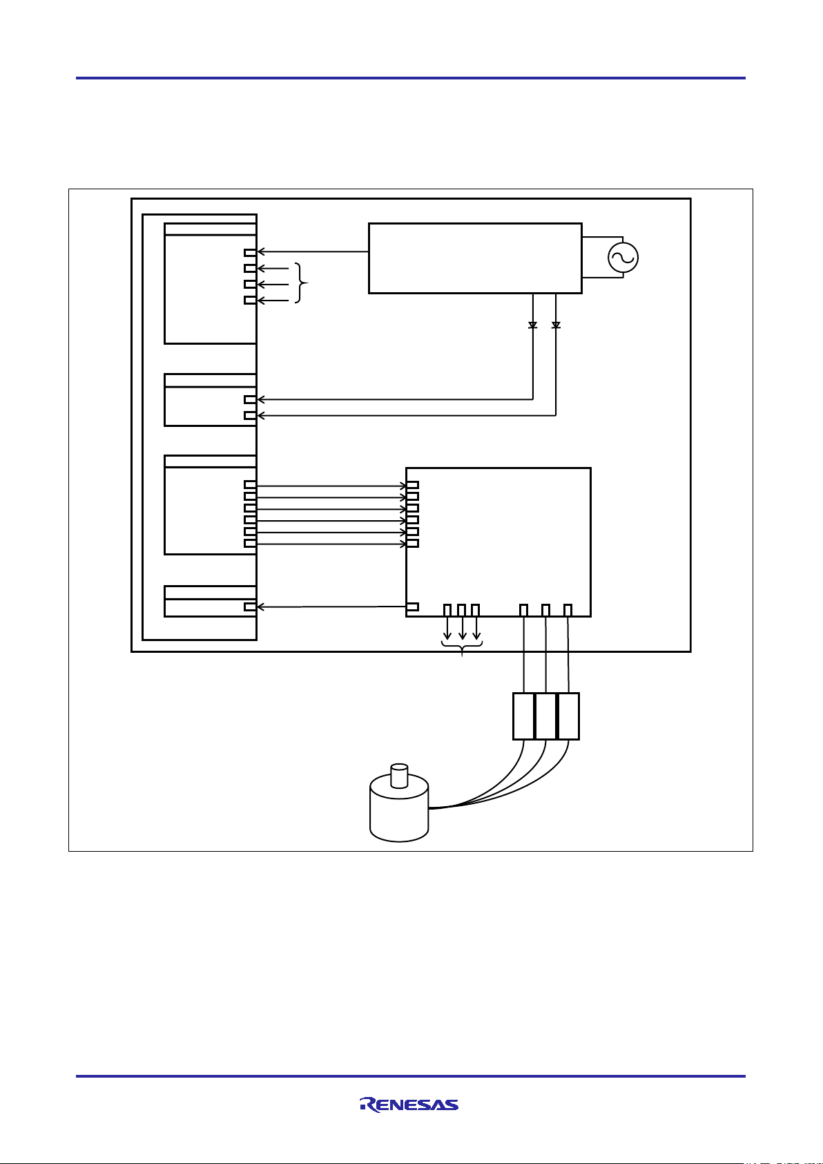
RX66T
A/D
converter
input
P62 / AN208
P40 / AN000
P41 / AN001
P42
/ AN002
LED output
PE3
PB7
P71/MTIOC3B(Up)
P72/MTIOC4A(Vp)
P73/MTIOC4B(Wp)
P74/MTIOC3D(Un)
P75/MTIOC4C(Vn)
P76/MTIOC4D(Wn)
MTU3c output
P70 / POE0#
Power supply circuit
Up
Vp
Wp
Un
Vn
Wn
OC
Inverter circuit
Iu Iv Iw Vw VuVv
LED1 LED2
AC input
Bus voltage
Iu_AIN
Iv_AIN
Iw_AIN
Phase currants
Phase
Current
detection
W port
V port
U port
3phase ACIM
Overcurrent detectio input
Overcurrent detection
2. System Overview
This section gives an overview of the system described in this application note.
2.1 Hardware Configuration
The hardware configuration is shown below.
Figure 2.1 Hardware Configuration
R01AN4673EJ0110 Rev.1.10 Page 5 of 45
Apr 21, 21
Page 6

RX66T Implementation
Vector Control of Three-Phase Induction
Motor Used in Driving a Fan
Item
Interface Component
Function
LED1
Yellow-green LED
• Motor is running: On
Motor is stopped: Off
LED2
Yellow-green LED
• An error is detected: On
• Normal operation: Off
RESET
Pushbutton switch RESET1
System reset
R5F566TEADFP Pin Name
Function
P62/AN208
Inverter bus voltage measurement
PE3
LED1 on/off control
PB7
LED2 on/off control
P40/AN000
Measurement of the U-phase current
P41/AN001
Measurement of the V-phase current
P42/AN002
Measurement of the W-phase current
P63/AN209*1
Measurement of the intelligent power module (IPM) temperature
P71/MTIOC3B
Complementary PWM output (Up)
P72/MTIOC4A
Complementary PWM output (Vp)
P73/MTIOC4B
Complementary PWM output (Wp)
P74/MTIOC3D
Complementary PWM output (Un)
P75/MTIOC4C
Complementary PWM output (Vn)
P76/MTIOC4D
Complementary PWM output (Wn)
P70/POE0#
Input for the emergency signal for stopping
the PWM output on detection of an overcurrent
2.2 Hardware Specifications
2.2.1 User Interface
Table 2.1 lists the user interfaces for use in this system.
Table 2.1 User Interfaces
•
Table 2.2 lists the pin interfaces for use in this system.
Table 2.2 Pin Interfaces
Note 1. Not connected on the CPU board (function is disabled)
R01AN4673EJ0110 Rev.1.10 Page 6 of 45
Apr 21, 21
Page 7

RX66T Implementation
Vector Control of Three-Phase Induction
Motor Used in Driving a Fan
MCU
12-bit ADC
CMT
MTU3d
POE3b
• Inverter bus voltage
2.2.2 Peripheral Modules
The peripheral modules for use with this system are listed below.
Table 2.3 Peripheral Modules for Use with the Sample Program
RX66T
•
Individual currents of
U/V/W phases
1-ms interval
timer
Complementary
PWM output
Initialization of the complementary PWM output port
(The pins being used for PWM output are placed in the high-
impedance state and PWM output is stopped)
(1) 12-bit A/D converter
Using 12-bit A/D converters to measure the U-, V-, and W-phase currents (I
voltage (V
).
dc
, Iv, and Iw), inverter bus
u
The operating mode differs for each converter unit. Unit 0 is set to group scan mode, with use of the
sample-and-hold function (use synchronous trigger to start conversion) and unit 2 is set to continuous
scan mode.
(2) Compare match timer (CMT)
Channel 0 of the compare match timer is used as a 1-ms interval timer.
(3) Multi-function timer pulse unit 3 (MTU3d)
The operating mode varies with channels, with channels 3 and 4 being used in complementary PWM
mode to output an active-high signal that includes dead time.
(4) Port output enable 3 (POE3)
When an overcurrent is detected (indicated by a falling edge on the POE0# pin) or when an output shortcircuit is detected, the pins being used for PWM output are placed in the high-impedance state, PWM
output is stopped, and the complementary PWM output port pins are initialized.
R01AN4673EJ0110 Rev.1.10 Page 7 of 45
Apr 21, 21
Page 8

RX66T Implementation
Vector Control of Three-Phase Induction
Motor Used in Driving a Fan
Sample Program
Name
File Name
Description
2.3 Software Configuration
2.3.1 File Configuration
Table 2.4 lists the folders and files for this sample program.
Table 2.4 Folders and Files for the Sample Program [1]
Folder
RX66T100_T1102_
3IM_LESS_FOC_
CSP_FAN_V100
Inc main.h Main function and user interface control header file
Ics ICS2_RX66T.lib ICS library
Src main.c Main function and user interface control header file
mtr_common.h Common definitions header file
mtr_ctrl_t1102.h Board-dependent processing header file
mtr_ctrl_rx66t100.h RX66T-dependent processing header file
mtr_3im_less_foc.h Sensorless vector control header file
control_parameter.h Control parameter header file
motor_parameter.h Motor parameter header file
mtr_ctrl_rx66t100_t1102.h Board- and RX66T-dependent processing header file
r_init_clock.h Hader file for initial setting of the clock signals for the RX66T
r_init_port_initialize.h Header file for initialization of the RX66T port pins
r_init_rom_cache.h Header file for initialization of the ROM cache of the RX66T
r_init_stop_module.h Header file for stop processing of peripheral modules of the
RX66T
ICS2_RX66T.h ICS library header file
mtr_ctrl_t1102.c Board-dependent processing
mtr_ctrl_rx66t100.c RX66T-dependent processing
mtr_interrupt.c Interrupt handlers
mtr_3im_less_foc.c Sensorless vector control
mtr_ctrl_rx66t100_t1102.c Board- and RX66T-dependent processing
r_init_clock.c Initial setting of the clock signals for the RX66T
r_init_port_initialize.c Initialization processing of the RX66T port pins
r_init_rom_cache.c Initialization processing of the ROM cache of the RX66T
r_init_stop_module.c Stop processing of the peripheral modules of the RX66T
R01AN4673EJ0110 Rev.1.10 Page 8 of 45
Apr 21, 21
Page 9
RX66T Implementation
Vector Control of Three-Phase Induction
Motor Used in Driving a Fan
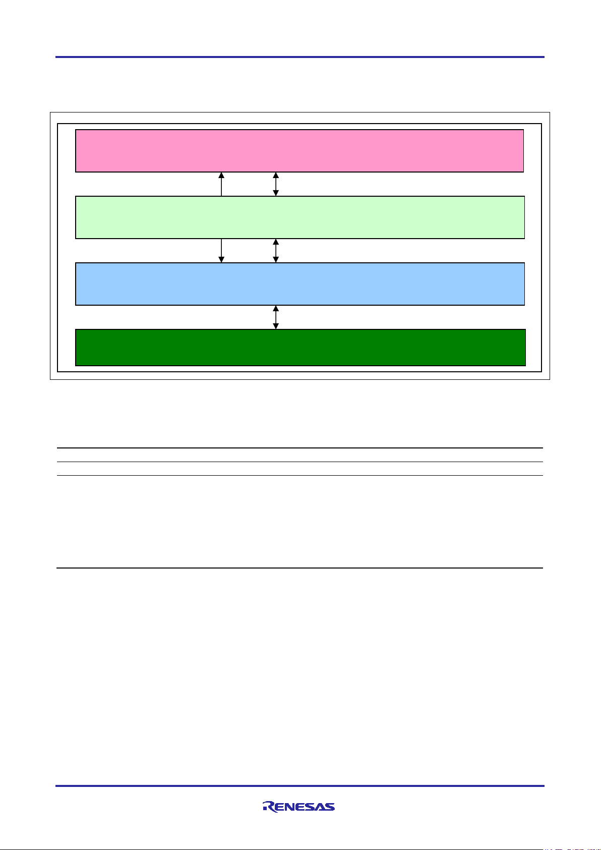
Layer
File
Application layer
main.c
Motor control layer
mtr_3im_less_foc.c
Hardware control layer
mtr_ctrl_rx66t100_t1102.c
r_init_stop_module.c
Application layer
Hardware control layer
Hardware
T1102 inverter board and the RX66T microcontroller
Motor control layer
2.3.2 Configuration of the Sample Program
The software modules used in this sample program are shown in Figure 2.2 and Table 2.5.
User interface control
Sensorless vector control
MCU-dependent processing and inverter board-dependent processing
Figure 2.2 Configuration of the Software Modules Used in the Sample Program
Table 2.5 Configuration of the Software Modules Used in the sample Program [1]
mtr_ctrl_rx66t100.c
mtr_ctrl_t1102.c
r_init_clock.c
r_init_port_initialize.c
r_init_rom_cache.c
R01AN4673EJ0110 Rev.1.10 Page 9 of 45
Apr 21, 21
Page 10

RX66T Implementation
Vector Control of Three-Phase Induction
Motor Used in Driving a Fan
Item
Description
Control method
Vector control
Starting and stopping of
Handled by RMW (See the ‘com_s2_mode_system’ variable in Table 4.1.)
Detection of rotor's
magnetic pole position
Sensorless
Input voltage
AC 220 V
Carrier frequency (PWM)
16 kHz
Control period
125 µs (twice the carrier period)
Rotational speed range
500 rpm to 2000 rpm *1
System protection
• The motor control signal outputs (6 lines) are set to the inactive level in
(detection of a falling edge on the POE0# pin).
2.4 Software Specifications
Table 2.6 lists the basic specifications of this system software. See the Motor Control Application: Vector
Control of Three-Phase Induction Motor (Algorithms) for details on the vector control.
Table 2.6 Basic Specifications of the Vector Control Program (for Sample Program [1])
motor rotation
response to any of the following four conditions.
1. The current in any phase exceeds 3 A (monitored once every 125 µs).
2. The inverter bus voltage exceeds 420 V (monitored once every 125
µs).
3. The inverter bus voltage falls below 0 V (monitored once every 125
µs).
4. The speed exceeds 2600 rpm (monitored once every 125 µs).
• The pins being used for PWM output are placed in the high-impedance
state in response to external input of an overcurrent detection signal
Note 1. There may be a difference between the actual speed and the reference speed depending on the
working environment.
R01AN4673EJ0110 Rev.1.10 Page 10 of 45
Apr 21, 21
Page 11

RX66T Implementation
Vector Control of Three-Phase Induction
Motor Used in Driving a Fan
Item
Sample
Program
Conversion Ratio
(Inverter bus voltage: A/D converted value)
Channel
Inverter bus voltage
[1]
0 V to 686.5 V: 0000H to 0FFFH
AN208
Item
Sample
Program
Conversion Ratio
(U-, V-, W-phase currents: A/D converted value)
Channel
U-, V-, W-phase
[1]
-50 A to 50 A: 0000H to 0FFFH
Iu: AN000
3. Control Program
This section describes the sample program covered in this application note.
3.1 Control
3.1.1 Starting and Stopping the Motor
Starting and stopping of the motor are controlled by using RMW to set a value to the motor operation
variable “com_s2_mode_system”.
The variable for motor operation is read in the main loop, and if the value is found to have been changed, it
is determined that the user has set by using PMW, and the state changes according to the value. As shown
in Table 4.1, write ‘1’ to the motor operation variable will change the motor to the running state, and write ‘0’
to the motor operation variable will change the motor to the stopped state. Also write ‘3’ to the motor
operation variable will reset the error state.
3.1.2 Motor Rotation Speed Command
Using RMW to set rotation speed command value in ‘com_s2_ref_speed_rpm’. The unit of the speed
command value is rpm.
3.1.3 Inverter Bus Voltage
As shown in the table below, the measured values of the inverter bus voltage are used in producing the
modulation factor and for overvoltage detection. Detection of abnormal voltages leads to stopping of the
PWM output.
Table 3.1 Conversion Ratio for Inverter Bus Voltage
3.1.4 Phase Current
As shown in the table below, the measured values of U-, V-, and W-phase currents are used for vector
control and overcurrent detection.
Table 3.2 Conversion Ratio for U-, V-, W-Phase Currents
currents
Iv: AN001
Iw: AN002
R01AN4673EJ0110 Rev.1.10 Page 11 of 45
Apr 21, 21
Page 12
RX66T Implementation
Vector Control of Three-Phase Induction
Motor Used in Driving a Fan
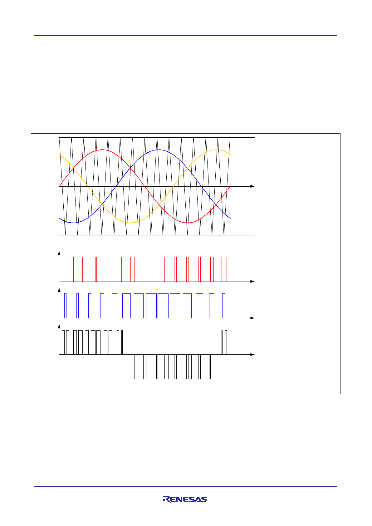
U V
W
ωt
ωt
ωt
ωt
U-phase switching waveform
V-phase switching waveform
Voltage between the U and V lines
(U-phase waveform) – (V-phase waveform)
Modulated wave: Command voltage value
Carrier wave (triangle wave): Produced through counting by the MTU3d timer
3.1.5 Modulation
In this sample program, the voltage to be input to the motor is generated by pulse width modulation (PWM).
Comparison of the PWM waveform with a triangular waveform determines the pulse width for use in
providing the input voltage.
(1) Triangle Wave Comparison Method
This is the method for the physical output of the desired voltage. The pulse width for the voltage to be output
is determined on the basis of the results of comparing the command voltage waveform with the carrier
waveform (triangle wave). The desired voltage is output as a pseudo-sinusoidal waveform by switching the
output on when the voltage is greater than that produced by the carrier wave and off when the voltage is
lower than that produced by the carrier wave.
Figure 3.1 Concepts of Triangle Wave Comparison Method
R01AN4673EJ0110 Rev.1.10 Page 12 of 45
Apr 21, 21
Page 13
RX66T Implementation
Vector Control of Three-Phase Induction
Motor Used in Driving a Fan
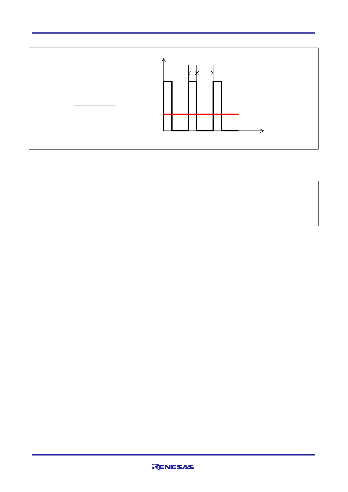
Average voltage
t
V
T
ON
T
OFF
T
ON
+ T
OFF
T
ON
Duty = × 100 [%]
E
V
m =
m: Modulation factor V: Command value voltage E: Inverter bus voltage
Here, as shown in Figure 3.2, the ratio of the output voltage pulse to the carrier wave is called duty.
The modulation factor m is defined as follows.
Figure 3.2 Definition of Duty
A desired control is accomplished by setting this modulation factor to the register for use in determining the
PWM duty.
R01AN4673EJ0110 Rev.1.10 Page 13 of 45
Apr 21, 21
Page 14
RX66T Implementation
Vector Control of Three-Phase Induction
Motor Used in Driving a Fan
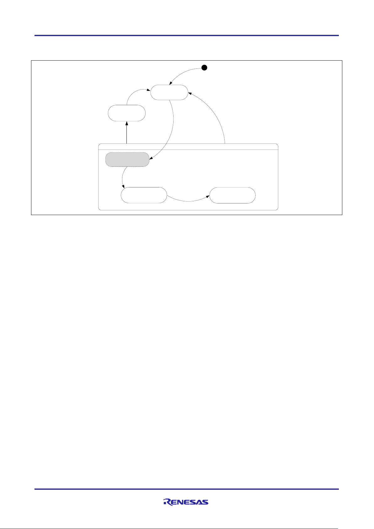
RUN MODE
START MODE
[ when offset current detection finish ]
BOOT MODE
CONTROL MODE
[ERROR EVENT]
ERROR MODE
STOP MODE
[RESET EVENT]
[STOP EVENT]
[RUN EVENT]
RESET
3.1.6 State Transitions
Figure 3.3 shows the state transitions within the sensorless vector control program.
Figure 3.3 State Transitions within the Sensorless Vector Control Program
R01AN4673EJ0110 Rev.1.10 Page 14 of 45
Apr 21, 21
Page 15

RX66T Implementation
Vector Control of Three-Phase Induction
Motor Used in Driving a Fan
Error
Item
Value
Overcurrent error
Overcurrent limit value [A]
3
Monitoring cycle [µs]
125
Overvoltage error
Overvoltage limit value [V]
420
Monitoring cycle [µs]
125
Undervoltage error
Undervoltage limit value [V]
0
Monitoring cycle [µs]
125
Rotational speed error
Speed limit value [rad/s] (electrical angle)
272
Monitoring cycle [µs]
125
3.1.7 System Protection Functions
This control program detects the following five errors and initiates an emergency stop in response to each of
them. See Table 3.3 for the values used for the system protection functions.
• Overcurrent error
The PWM output pins are placed in the high-impedance state in response to an emergency stop signal
(over current detection) from the hardware.
In addition, U-, V-, and W-phase currents are monitored in overcurrent monitoring cycles. When an
overcurrent (the current exceeding the overcurrent limit value) is detected, the CPU initiates an
emergency stop of the PWM output (in response to detection by the software).
• Overvoltage error
The inverter bus voltage is monitored in overvoltage monitoring cycles. When an overvoltage (the voltage
exceeding the overvoltage limit value) is detected, the CPU initiates an emergency stop of the PWM
output.
• Undervoltage error
The inverter bus voltage is monitored in low-voltage monitoring cycles. The CPU initiates an emergency
stop of the PWM output when low voltage (the voltage falls below the limit value) is detected.
• Rotational speed error
Rotational speed is monitored in speed monitoring cycles and if the speed limit is exceeded, the CPU
initiates an emergency stop of the PWM output.
Table 3.3 Values for the System Protection Functions in Sample Program [1]
R01AN4673EJ0110 Rev.1.10 Page 15 of 45
Apr 21, 21
Page 16

RX66T Implementation
Vector Control of Three-Phase Induction
Motor Used in Driving a Fan
File Name
Function Name
Processing Overview
•
3.2 Functions for Use in Vector Control Software Program
The control program uses multiple control functions as listed in the table below. See the flowcharts and the
source code for more detailed information on the processing performed by these functions.
Table 3.4 Control Functions (1/7)
main.c main
Input: None
Output: None
Calls the hardware initialization function
• Calls the user interface initialization function
• Calls the main processing variables initialization function
• Calls the function to execute state transitions and events
• Main processing
⇒ Calls the function that performs the main processing
ics_ui
Input: None
Output: None
software_init
Input: None
Output: None
mtr_ctrl_t1102.c R_MTR_ChargeCapacitor
Input: None
Output: None
ic_gate_on
Input: None
Output: None
led1_on
Input: None
Output: None
led2_on
Input: None
Output: None
led1_off
Input: None
Output: None
led2_off
Input: None
Output: None
get_sw1
Input: None
Output: (uint8) u1_temp/ the state of SW1
get_sw2
Input: None
Output: (uint8) u1_temp/ the state of SW2
get_sw3
Input: None
Output: (uint8) u1_temp/ the state of SW3
get_vr1
Input: None
Output: (uint16) u2_temp/ rotational speed
command
⇒ Calls the watchdog timer clear function
For use by the ICS user interface
Initializes variables used in the main processing
Waits for the charging time for the smoothing capacitor
Sets the gate signal used for inrush prevention to the ON state
Turns on LED1
Turns on LED2
Turns off LED1
Turns off LED2
Gets the state of SW1
Gets the state of SW2
Gets the state of SW3
Gets the A/D converted value of the rotational speed
command
R01AN4673EJ0110 Rev.1.10 Page 16 of 45
Apr 21, 21
Page 17

RX66T Implementation
Vector Control of Three-Phase Induction
Motor Used in Driving a Fan
File Name
Function Name
Processing Overview
Output: None
Output: None
Output: None
File Name
Function Name
Processing Overview
Output: None
Calls the function that clears the high-impedance state
• Current PI control
Speed PI control
Table 3.4 Control Functions (2/7)
mtr_ctrl_rx66t100.c R_MTR_InitHardware
Input: None
mtr_init_cmt
Input: None
Output: None
mtr_init_poe3
Input: None
init_wdt
Input: None
Output: None
clear_wdt
Input: None
Output: None
mtr_clear_oc_flag
Input: None
Output: None
mtr_clear_cmt0_flag
Input: None
Table 3.4 Control Functions (3/7)
Initializes clock signals and peripheral modules
Initializes the CMT
Initializes the POE3
Initializes the WDT
Clears the WDT
Releases the high-impedance state
Clears the interrupt flag
mtr_interrupt.c mtr_groupBL1_interrupt
Input: None
mtr_over_current_interrupt
Input: None
Output: None
mtr_mtu4_interrupt
Input: None
Output: None
mtr_cmt0_interrupt
Input: None
Output: None
Group interrupt which includes an overcurrent detection as a
source
•
Calls the overcurrent detection processing
Overcurrent detection processing
• Calls the event processing selection function
• Changes the motor status
•
Called once every 125 µs
• Vector control
Called once every 1 ms
• Startup control
•
R01AN4673EJ0110 Rev.1.10 Page 17 of 45
Apr 21, 21
Page 18

RX66T Implementation
Vector Control of Three-Phase Induction
Motor Used in Driving a Fan
File Name
Function Name
Processing Overview
Output: None
•
Output: (uint8)u1_state/ motor status
Output: (uint8)u1_state/ motor status
Output: None
Table 3.4 Control Functions (4/7)
mtr_3im_less_foc.c R_MTR_InitSequence
Input: None
R_MTR_ExecEvent
Input: (uint8)u1_event/ event that occur
Output: None
mtr_act_run
Input: (uint8)u1_state/ motor status
mtr_act_stop
Input: (uint8)u1_state/ motor status
Output: (uint8)u1_state/ motor status
mtr_act_none
Input: (uint8)u1_state/ motor status
Output: (uint8)u1_state/ motor status
mtr_act_reset
Input: (uint8)u1_state/ motor status
Output: (uint8)u1_state/ motor status
mtr_act_error
Input: (uint8)u1_state/ motor status
mtr_start_init
Input: None
Output: None
mtr_stop_init
Input: None
Sequence processing initialization
Updates the motor state
• Calls the function that handles the appropriate
processing in response to events that occur
•
Calls the function that initializes the variables used at
motor startup
•
Calls the function that starts motor control
Calls the function that terminates motor control
No processing
Initializes global variables
Calls the function that terminates motor control
Initializes only those variables needed at motor startup
Initializes variables needed at motor stop
mtr_pi_ctrl
Input: MTR_PI_CTRL *pi_ctrl/ structure for PI
control
Output: (float32)f4_ref/ PI control output value
mtr_set_variables
Input: None
Output: None
R_MTR_IcsInput
Input: MTR_ICS_INPUT *ics_input/ structure for
ICS
Output: None
Used in PI control
Sets the motor variables
Sets up buffers
R01AN4673EJ0110 Rev.1.10 Page 18 of 45
Apr 21, 21
Page 19

RX66T Implementation
Vector Control of Three-Phase Induction
Motor Used in Driving a Fan
File Name
Function Name
Processing Overview
Output: None
Output: (uint8)g_u1_direction
Output: None
Output: None
Table 3.4 Control Functions (5/7)
R_MTR_SetDir
Input: (uint8)dir/ rotational direction
R_MTR_GetSpeed
Input: None
Output: (float32)f4_speed_rpm/ speed
R_MTR_GetDir
Input: None
R_MTR_GetStatus
Input: None
Output: (uint8)g_u1_mode_system/ motor staus
mtr_error_check
Input: None
Output: None
mtr_set_speed_ref
Input: None
Output: None
mtr_set_iq_ref
Input: None
mtr_set_id_ref
Input: None
Output: None
mtr_calc_mod
Input: (float32) f4_vu/ U-phase voltage
(float32) f4_vv/ V-phase voltage
(float32) f4_vw/ W-phase voltage
(float32) f4_vdc/ bus voltage
Sets the direction of rotation
Acquires the speed calculation value
Acquires the value of the rotational direction
Acquires the motor status
Error monitoring and detection
Sets the command used for speed control
Sets the δ axis current command
Sets the γ axis current command
Modulation factor calculation
R01AN4673EJ0110 Rev.1.10 Page 19 of 45
Apr 21, 21
Page 20

RX66T Implementation
Vector Control of Three-Phase Induction
Motor Used in Driving a Fan
File Name
Function Name
Processing Overview
Output: None
Output: None
Output: None
Output: None
Table 3.4 Control Functions (6/7)
mtr_ctrl_rx66t_t1102.c mtr_init_mtu
Input: None
mtr_init_io_port
Input: None
Output: None
mtr_init_ad_converter
Input: None
init_ui
Input: None
Output: None
mtr_ctrl_start
Input: None
Output: None
mtr_ctrl_stop
Input: None
Output: None
mtr_get_iuiviwvdc
Input: (float32)*f4_iu_ad/ A/D converted value of U-phase
current
(float32)*f4_iv_ad/ A/D converted value of V-phase
current
(float32)*f4_iw_ad/ A/D converted value of W-phase
current
(float32)*f4_vdc_ad/ A/D converted value of Vdc
Initialization of the MTU3d
Initialization of the I/O ports
Initialization of the A/D converters
Initialization of the user interfaces
Motor startup processing
Motor stop processing
A/D conversion of U-, V-, and W-phase
currents and inverter bus voltage
mtr_get_ipm_temperature
Input: None
Output: (int16)s2_temp/A/D converted value of the IPM
temperature voltage
mtr_clear_mtu4_flag
Input: None
mtr_inv_set_uvw
Input: (float32)f4_modu/ U phase modulation factor
(float32)f4_modv/ V phase modulation factor
(float32)f4_modw/ W phase modulation factor
Output: None
mtr_init_register
Input: None
Output: None
A/D conversion of the IPM temperature
Clears the interrupt flag
PWM output setting
Initialization for the PWM value comparison
R01AN4673EJ0110 Rev.1.10 Page 20 of 45
Apr 21, 21
Page 21

RX66T Implementation
Vector Control of Three-Phase Induction
Motor Used in Driving a Fan
File Name
Function Name
Processing Overview
Output: None
Output: None
Output: None
Table 3.4 Control Functions (7/7)
r_init_clock.c R_INIT_Clock
Input: None
CGC_oscillation_main
Input: None
Output: None
CGC_oscillation_PLL
Input: None
CGC_oscillation_HOCO
Input: None
Output: None
r_init_port_initialize.c R_INIT_Port_Initialize
Input: None
Output: None
r_init_rom_cache.c R_INIT_ROM_Cache
Input: None
Output: None
r_init_stop_module.c R_INIT_StopModule
Input: None
Initialization of the clock signals
Main clock oscillation setting
PLL clock oscillation setting
HOCO clock oscillation setting
Initialization of ports that are not present
Initialization of the ROM cache
Stops peripheral modules which are running after a reset
R01AN4673EJ0110 Rev.1.10 Page 21 of 45
Apr 21, 21
Page 22

RX66T Implementation
Vector Control of Three-Phase Induction
Motor Used in Driving a Fan
Variable Name
Type
Content
Remark
3.3 Software Variables Used in the Sensorless Vector Control Program
The table below lists the variables used in the control program.
Table 3.5 List of Variables (1/3)
g_u1_mode_system uint8 State management 0: Stop mode
1: Run mode
2: Error mode
g_u2_run_mode uint16 Operating mode management 0: Boot mode
2: Control mode
g_u2_ctrl_mode uint16 Control mode management 1: Open loop mode
5: Sensorless vector control mode
g_u1_error_status uint8 Error status management 1: Overcurrent error
2: Overvoltage error
3: Rotational speed error
7: Low voltage error
8: IPM temperature error
0xFF: Undefined error
g_f4_vdc_ad float32 Inverter bus voltage [V]
g_f4_vd_ref float32 γ axis output voltage command [V]
g_f4_vq_ref float32 δ axis output voltage command [V]
g_f4_iu_ad float32 U-phase current [A]
g_f4_pre_iu_ad float32 Previous U-phase current value [A]
g_f4_iv_ad float32 V-phase current [A]
g_f4_pre_iv_ad float32 Previous V-phase current value [A]
g_f4_iw_ad float32 W-phase current [A]
g_f4_pre_iw_ad float32 Previous W-phase current value [A]
g_f4_offset_iu float32 U-phase current offset [A]
g_f4_offset_iv float32 V-phase current offset [A]
g_f4_offset_iw float32 W-phase current offset [A]
g_f4_id_lpf float32 γ axis current [A]
g_f4_iq_lpf float32 δ axis current [A]
g_f4_pre_id_lpf float32 Previous γ axis current value [A]
g_f4_pre_iq_lpf float32 Previous δ axis current value [A]
g_f4_kp_id float32 γ axis current PI control proportional
gain
g_f4_ki_id float32 γ axis current PI control integral gain
g_f4_lim_id float32 γ axis current PI control limit value [A]
g_f4_ilim_id float32 γ axis current PI control integral limit
value
g_f4_kp_iq float32 δ axis current axis current PI control
proportional gain
g_f4_ki_iq float32 δ PI control integral gain
g_f4_lim_rotor_speed_rad float32 Rotor speed PI control limit value Electrical angle [rad/s]
g_f4_ilim_rotor_speed_rad float32 Rotor speed PI control integral limit
value
g_f4_id_ref float32 γ axis current command [A]
g_f4_iq_ref float32 δ axis current command [A]
g_f4_ref_stator_speed_rad float32 Stator speed command Electrical angle [rad/s]
[A]
Electrical angle [rad/s]
R01AN4673EJ0110 Rev.1.10 Page 22 of 45
Apr 21, 21
Page 23

RX66T Implementation
Vector Control of Three-Phase Induction
Motor Used in Driving a Fan
Variable Name
Type
Content
Remark
g_f4_slip_speed_rad
float32
Slip speed
Electrical angle [rad/s]
g_f4_speed_rad
float32
Calculated speed value
Electrical angle [rad/s]
g_f4_ref_speed_rad
float32
Speed command
Electrical angle [rad/s]
g_f4_max_speed_rad
float32
Maximum speed command value
[rad/s]
g_f4_refu
float32
U-phase voltage command
[V]
g_f4_refw
float32
W-phase voltage command
[V]
g_f4_speed_lpf_k
float32
Speed LPF gain
g_f4_offset_lpf_k
float32
Current offset LPF gain
control)
value
g_f4_offset_calc_time
float32
Current offset calculation time
[ms]
g_f4_voltage_drop_k
float32
Voltage drop correction gain
g_f4_modv
float32
V phase modulation factor
rotor_speed
MTR_PI_CTRL
Rotor speed PI control structure
Table 3.5 List of Variables (2/3)
g_f4_slip_k float32 Slip speed gain
g_f4_ref_speed_rad_pi float32 Calculated value for speed PI control Electrical angle [rad/s]
g_f4_angle_rad float32 Rotor interlinkage flux phase [rad]
g_f4_min_speed_rad float32 Minimum speed command value [rad/s]
g_f4_refv float32 V-phase voltage command [V]
g_f4_inv_limit float32 Phase voltage limit value [V]
g_f4_current_lpf_k float32 Current LPF gain
g_u1_direction uint8 Rotational direction command 0: CW
1: CCW
g_u1_enable_write uint8 Variable for use by the user interface of
the ICS
g_u2_cnt_adjust uint16 Counter for use in current offset
calculation
g_u1_flag_id_ref uint8 γ axis current command management
flag
0: γ axis current increases
1: γ axis current is constant
2: γ axis current is constant (speed
g_f4_temp_speed_rad float32 Variable for holding speed value Electrical angle [rad/s]
g_f4_temp_ref_speed_rad float32 Variable for holding speed command
g_f4_angle_compensation float32 Phase compensation constant
g_f4_voltage_drop float32 Voltage drop correction threshold [V]
g_f4_modu float32 U phase modulation factor
g_f4_modw float32 W phase modulation factor
id_ACR MTR_PI_CTRL γ axis current PI control structure
Electrical angle [rad/s]
R01AN4673EJ0110 Rev.1.10 Page 23 of 45
Apr 21, 21
Page 24

RX66T Implementation
Vector Control of Three-Phase Induction
Motor Used in Driving a Fan
Variable Name
Type
Content
Remark
g_f4_kp_speed
float32
Speed PI control proportional gain
g_f4_lim_iq
float32
axis current PI control limit value
[A]
1: Speed changes
Table 3.5 List of Variables (3/3)
g_f4_ki_speed float32 Speed PI control integral gain
δ
g_f4_ilim_iq float32 δ axis current PI control integral limit
value
g_u1_dir_buff uint8 Variable for storing the commanded
rotational direction
g_f4_id_ref_buff float32 Variable for storing γ axis current
command
g_f4_iq_ref_buff float32 Variable for storing δ axis current
command
g_u1_flag_iq_ref uint8 δ axis current command management
flag
g_u1_flag_speed_ref uint8 Speed command management flag 0: Speed = 0
[A]
0: CW
1: CCW
[A]
[A]
0: δ axis current 0
1: Speed PI output
mtr_p MTR_PARAMETER Motor parameters and control
parameters
g_u1_flag_offset_calc uint8 Current offset calculation flag 0: Calculated at transition to boot
g_f4_boot_id_up_step float32 γ axis current additional value at startup [A]
g_f4_fluctuation_limit float32 Speed fluctuation limit [rad/s]
g_f4_ctrl_ref_id float32 γ axis current command [A]
g_u2_cnt_id_const uint16 γ axis current flux stabilization wait time
counter
g_f4_id_const_time float32 γ axis current flux stabilization wait time [ms]
g_f4_accel float32 Acceleration [rad/s2]
g_f4_ipm_temperature_ad float32 The IPM temperature that is converted
to voltage
speed MTR_PI_CTRL Structure for use in speed PI control
ics_input_buff MTR_ICS_INPUT Structure for the ICS user interface
mode
1: Calculated at transition to boot
mode (first time only)
[V]
R01AN4673EJ0110 Rev.1.10 Page 24 of 45
Apr 21, 21
Page 25

RX66T Implementation
Vector Control of Three-Phase Induction
Motor Used in Driving a Fan
Member Name
Type
Description
Remarks
f4_err
float32
Differential
f4_kp
float32
PI control proportional gain
f4_ki
float32
PI control integral gain
f4_limit
float32
PI control output limit value
f4_refi
float32
PI control integral output value
f4_ilimit
float32
PI control integral limit value
f4_mtr_rs
float32
Stator resistance
[Ω]
f4_mtr_rr
float32
Rotor resistance
[Ω]
f4_mtr_m
float32
Magnetizing inductance
[H]
f4_mtr_ls
float32
Stator leakage inductance
[H]
f4_mtr_lr
float32
Rotor leakage inductance
[H]
f4_mtr_m_lr
float32
f4_mtr_m/f4_mtr_lr
f4_mtr_rr_lr
float32
f4_mtr_rr/f4_mtr_lr
f4_mtr_sigma
float32
1.0 - f4_mtr_m/f4_mtr_ls * f4_mtr_m_lr
f4_mtr_ls_sigma
float32
f4_mtr_ls * f4_mtr_sigma
[rpm]
1: CCW
f4_kp_speed
float32
Speed PI control proportional gain
f4_ki_speed
float32
Speed PI control integral gain
f4_kp_iq
float32
axis current PI control proportional gain
f4_ki_iq
float32
axis current PI control integral gain
f4_speed_lpf_k
float32
Speed LPF gain
f4_current_lpf_k
float32
Current LPF gain
f4_mtr_rs
float32
Stator resistance
[Ω]
f4_mtr_rr
float32
Rotor resistance
[Ω]
f4_mtr_m
float32
Magnetizing inductance
[H]
f4_mtr_lls
float32
Stator leakage inductance
[H]
f4_mtr_llr
float32
Rotor leakage inductance
[H]
f4_offset_lpf_k
float32
Current offset value LPF gain
[rpm]
[rpm]
f4_ctrl_ref_id
float32
axis current command
[A]
f4_boot_id_up_time
float32
Rise time at γ axis current startup
[ms]
f4_id_const_time
float32
axis current/flux stabilization wait time
[ms]
acceleration/deceleration step size
f4_fluctuation_limit
float32
Speed fluctuation limit
[rad/s]
coefficient
f4_offset_calc_time
float32
Current offset adjustment time
[ms]
f4_voltage_drop
float32
Voltage drop correction threshold
[V]
f4_voltage_drop_k
float32
Voltage drop correction gain
3.4 Structures Used in the Sensorless Vector Control Software
The table below lists the structures used in the control program.
Table 3.6 List of Structures
MTR_PI_CTRL
MTR_PARAMETER
MTR_ICS_INPUT s2_ref_speed int16 Speed command Mechanical angle
s2_direction int16 Rotational direction 0: CW
δ
δ
s2_max_speed int16 Maximum speed Mechanical angle
s2_min_speed int16 Minimum speed Mechanical angle
γ
γ
f4_accel float32 Rotational speed command
f4_delay float32 Voltage output delay compensation
R01AN4673EJ0110 Rev.1.10 Page 25 of 45
Apr 21, 21
Page 26

RX66T Implementation
Vector Control of Three-Phase Induction
Motor Used in Driving a Fan
File Name
Macro Name
Definition Value
Remarks
File Name
Macro Name
Definition Value
Remarks
3.5 Sensorless Vector Control Software Macros
The table below lists the macro definitions used in this control program.
Table 3.7 List of Macro Definitions (1/12)
main.h MAX_SPEED CP_MAX_SPEED_RPM Maximum value of the speed command
(mechanical angle) [rpm]
MIN_SPEED CP_MIN_SPEED_RPM Minimum value of the speed command
(mechanical angle) [rpm]
IQ_PI_KP CP_IQ_PI_KP δ axis current PI control proportional gain
IQ_PI_KI CP_IQ_PI_KI δ axis current PI control integral gain
SPEED_PI_KP CP_SPEED_PI_KP Speed PI control proportional gain
SPEED_PI_KI CP_SPEED_PI_KI Speed PI control integral gain
SPEED_LPF_K CP_SPEED_LPF_K Speed LPF gain
CURRENT_LPF_K CP_CURRENT_LPF_K Current LPF gain
STATOR_RESISTANCE MP_STATOR_RESISTANCE Stator resistance [Ω]
ROTOR_RESISTANCE MP_ROTOR_RESISTANCE Rotor resistance [Ω]
MUTUAL_INDUCTANCE MP_MUTUAL_INDUCTANCE Magnetizing inductance [H]
STATOR_LEAKAGE_
INDUCTANCE
ROTOR_LEAKAGE_
INDUCTANCE
OFFSET_LPF_K CP_OFFSET_LPF_K Current offset value LPF gain
CTRL_REF_ID CP_CTRL_REF_ID γ axis current command [A]
BOOT_ID_UP_TIME CP_BOOT_ID_UP_TIME Rise time at γ axis current startup [ms]
ID_CONST_TIME CP_ID_CONST_TIME γ axis current flux stabilization wait time [ms]
ACCEL_MODE0 CP_ACCEL_MODE0 Acceleration
FLUCTUATION_LIMIT CP_FLUCTUATION_LIMIT Speed fluctuation limit
DELAY CP_DELAY Voltage output delay compensation
OFFSET_CALC_TIME CP_OFFSET_CALC_TIME Current offset calculation time [ms]
VOLTAGE_DROP CP_VOLTAGE_DROP Voltage drop compensation threshold [V]
VOLTAGE_DROP_K CP_VOLTAGE_DROP_K Voltage drop compensation gain
POLE_PAIRS MP_POLE_PAIRS Constant used for pole pairs count correction
M_CW 0 Rotational direction
M_CCW 1
ICS_INT_LEVEL 6 ICS interrupt priority level
SW_ON 1 Active-high
SW_OFF 0
Table 3.7 List of Macro Definitions (2/12)
MP_STATOR_LEAKAGE_
INDUCTANCE
MP_ROTOR_LEAKAGE_
INDUCTANCE
Stator leakage inductance [H]
Rotor leakage inductance [H]
coefficient
motor_parameter.h MP_POLE_PAIRS 1 Pole pairs count
MP_STATOR_RESISTANCE 25.0 Stator resistance [Ω]
MP_ROTOR_RESISTANCE 12.5 Rotor resistance [Ω]
MP_MUTUAL_INDUCTANCE 1.00 Magnetizing inductance [H]
MP_STATOR_LEAKAGE_INDUCTANCE 0.080 Stator leakage inductance [H]
MP_INDUCTANCE 0.080 Rotor leakage inductance [H]
R01AN4673EJ0110 Rev.1.10 Page 26 of 45
Apr 21, 21
Page 27

RX66T Implementation
Vector Control of Three-Phase Induction
Motor Used in Driving a Fan
File Name
Macro Name
Definition Value
Remarks
MTR_PWM_TIMER_FREQ
160.0
PWM timer count frequency [MHz]
MTR_DEADTIME
2.5
Dead time [µs]
[MHz]
MTR_AD_FREQ
+ MTR_DEADTIME_SET
MTR_PORT_UP
PORT7.PODR.BIT.B1
U phase (positive phase) output port
MTR_PORT_VP
PORT7.PODR.BIT.B2
V phase (positive phase) output port
MTR_PORT_WP
PORT7.PODR.BIT.B3
W phase (positive phase) output port
MTR_PORT_LED1
PORTE.PODR.BIT.B3
LED1 output port
MTR_LED_ON
0
MTR_INPUT_V
220 * 1.41421356
Power supply voltage [V]
MTR_HALF_VDC
MTR_INPUT_V/2.0
Power supply voltage / 2 [V]
of the measured current
SCALING
of the measured IPM temperature
MTR_OVERVOLTAGE_LIMIT
420.0
High voltage limit value [V]
LIMIT
MTR_IC_GATE_ON
1
MTR_PORT_SW2
PORT1.PIDR.BIT.B1
SW2 input port
Table 3.7 List of Macro Definitions (3/12)
mtr_ctrl_rx66t100_
t1102.h
MTR_CARRIER_FREQ 16.0 Carrier frequency [kHz]
MTR_DEADTIME_SET MTR_DEADTIME *
MTR_PWM_TIMER_FREQ
MTR_AD_FREQ 40.0 A/D converter operating frequency
MTR_AD_SAMPLING_CYCLE 45.0 A/D conversion cycle count
MTR_AD_SAMPLING_TIME MTR_AD_SAMPLING_CYCLE /
MTR_AD_TIME_SET MTR_PWM_TIMER_FREQ *
MTR_AD_SAMPLING_TIME
MTR_CARRIER_SET (MTR_PWM_TIMER_FREQ *
1000 / MTR_CARRIER_FREQ / 2)
MTR_HALF_CARRIER_SET MTR_CARRIER_SET / 2 Carrier setting (intermediate value)
MTR_PORT_UN PORT7.PODR.BIT.B4 U phase (negative phase) output port
MTR_PORT_VN PORT7.PODR.BIT.B5 V phase (negative phase) output port
MTR_PORT_WN PORT7.PODR.BIT.B6 W phase (negative phase) output port
MTR_PORT_LED2 PORTB.PODR.BIT.B7 LED2 output port
MTR_LED_OFF 1
Dead time setting
A/D conversion time [µs]
Setting used to assure the A/D
conversion time
Carrier setting
Low active
MTR_IC_GATE_ON_V MTR_INPUT_V * 0.8 Power supply voltage × 80%[V]
MTR_ADC_SCALING 0x7FF ADC offset adjustment constant
MTR_CURRENT_SCALING 100.0f/4095.0 Resolution for use in A/D conversion
MTR_VDC_SCALING 686.0f/4095.0 Resolution for use in A/D conversion
of the measured inverter bus voltage
MTR_IPMTEMPERATURE_
MTR_OVERCURRENT_LIMIT 3.0 Current limit value [A]
MTR_UNDERVOLTAGE_
LIMIT
MTR_
OVERIPMTEMPERATURE_
MTR_PORT_IC_GATE PORT2.PODR.BIT.B4 Inrush current prevention circuit ports
MTR_PORT_SW1 PORT1.PIDR.BIT.B0 SW1 input port
MTR_PORT_SW3 PORT8.PIDR.BIT.B2 SW3 input port
5.0f/4095.0 Resolution for use in A/D conversion
0.0 Low voltage limit value [V]
3 IPM temperature limit value [V]
R01AN4673EJ0110 Rev.1.10 Page 27 of 45
Apr 21, 21
Page 28

RX66T Implementation
Vector Control of Three-Phase Induction
Motor Used in Driving a Fan
File Name
Macro Name
Definition Value
Remarks
MTR_INT_DECIMATION
1
Interrupt decimation count
(MTR_INT_DECIMATION + 1)
MTR_RS
MP_STATOR_RESISTANCE
Stator resistance [Ω]
MTR_M
MP_MUTUAL_INDUCTANCE
Magnetizing inductance [H]
INDUCTANCE
MTR_LR
MTR_M + MTR_LLR
MTR_RR_LR
MTR_RR / MTR_LR
MTR_LS_SIGMA
MTR_LS * MTR_SIGMA
MTR_TWOPI_3
MTR_TWOPI / 3
2π / 3
MTR_SQRT_3
1.7320508f
√3
MTR_RPM_RAD
MTR_TWOPI / 60
2π / 60
MTR_IQ_PI_KI
CP_IQ_PI_KI
axis current PI control integral gain
MTR_SPEED_PI_KI
CP_SPEED_PI_KI
Speed PI control integral gain
MTR_CURRENT_LPF_K
CP_CURRENT_LPF_K
Current LPF gain
value [A]
MTR_LIMIT_IQ
1.0
Speed PI control output limit value [A]
[rpm]
[rpm]
Table 3.7 List of Macro Definitions (4/12)
mtr_3im_less_
foc.h
MTR_CTRL_PERIOD (MTR_INT_DECIMATION + 1) /
(MTR_CARRIER_FREQ * 1000)
MTR_CONTROL_FREQ (MTR_CARRIER_FREQ * 1000) /
MTR_POLE_PAIRS MP_POLE_PAIRS Pole pairs count
MTR_RR MP_ROTOR_RESISTANCE Rotor resistance [Ω]
Control period [s]
Control frequency [Hz]
MTR_LLS MP_STATOR_LEAKAGE_
INDUCTANCE
MTR_LLR MP_ROTOR_LEAKAGE_
MTR_LS MTR_M + MTR_LLS
MTR_M_LR MTR_M / MTR_LR
MTR_SIGMA 1.0f - MTR_M / MTR_LS * MTR_M_LR
MTR_TWOPI 2 * 3.14159265 2π
MTR_SQRT_2 1.41421356f √2
MTR_SQRT_2_3 0.81649658f √(2/3)
MTR_IQ_PI_KP CP_IQ_PI_KP δ axis current PI control proportional
MTR_SPEED_PI_KP CP_SPEED_PI_KP Speed PI control proportional gain
MTR_SPEED_LPF_K CP_SPEED_LPF_K Speed LPF gain
Stator leakage inductance [H]
Rotor leakage inductance [H]
gain
δ
MTR_OFFSET_LPF_K CP_OFFSET_LPF_K Current offset value LPF gain
MTR_LIMIT_ID 3.0 γ axis current PI control output limit
MTR_I_LIMIT_ID 3.0 γ xis current PI control integral limit
value [A]
MTR_I_LIMIT_IQ 1.0 Speed PI control integral limit value[A]
MTR_MAX_SPEED_RPM CP_MAX_SPEED_RPM Maximum speed (mechanical angle)
MTR_MAX_SPEED_RAD MTR_MAX_SPEED_RPM *
MTR_POLE_PAIRS*MTR_TWOPI / 60
MTR_MIN_SPEED_RPM CP_MIN_SPEED_RPM Minimum speed (mechanical angle)
MTR_MIN_SPEED_RAD MTR_MIN_SPEED_RPM *
MTR_POLE_PAIRS*MTR_TWOPI / 60
Maximum speed (electrical angle)
[rad/s]
Minimum speed (electrical angle)
[rad/s]
R01AN4673EJ0110 Rev.1.10 Page 28 of 45
Apr 21, 21
Page 29

RX66T Implementation
Vector Control of Three-Phase Induction
Motor Used in Driving a Fan
File Name
Macro Name
Definition Value
Remarks
MTR_SPEED_LIMIT
MTR_MAX_SPEED_RAD * 1.3
Speed limit value [rad/s]
SPEED_RAD
value [rad/s]
MTR_BOOT_ID_UP_TIME
CP_BOOT_ID_UP_TIME
Rise time at γ axis current startup [ms]
Table 3.7 List of Macro Definitions (5/12)
mtr_3im_less_
foc.h
MTR_LIMIT_ROTOR_SPEED_
RAD
MTR_I_LIMIT_ROTOR_
MTR_CTRL_REF_ID CP_CTRL_REF_ID γ axis current command
MTR_MAX_SPEED_RAD * 1.2 δ axis current PI control output limit value
[rad/s]
MTR_MAX_SPEED_RAD * 1.2 δ axis current PI control integral limit
MTR_BOOT_ID_UP_STEP CP_CTRL_REF_ID/MTR_BOOT_
ID_UP_TIME
Step size at γ axis current startup
R01AN4673EJ0110 Rev.1.10 Page 29 of 45
Apr 21, 21
Page 30

RX66T Implementation
Vector Control of Three-Phase Induction
Motor Used in Driving a Fan
File Name
Macro Name
Definition Value
Remarks
MTR_ID_CONST_TIME
CP_ID_CONST_TIME
axis current/flux stabilization wait time [ms]
MTR_FLUCTUATION_LIMIT
CP_FLUCTUATION_LIMIT
Speed fluctuation limit [rad/s]
MTR_CTRL_PERIOD
MTR_VOLTAGE_DROP
CP_VOLTAGE_DROP
Voltage drop correction threshold [V]
MTR_EVERY_TIME
0
Current value calculation
MTR_CW
0
MTR_FLG_CLR
0
MTR_ID_UP
0 γ axis current increases
MTR_ID_CONST_CTRL
2
Normal operation
MTR_IQ_SPEED_PI_OUTPUT
1
Normal operation
MTR_START_MODE
0x01
Start mode
MTR_ZERO_PEC_MODE
0x00
Zero-position measurement mode
MTR_HALL_120_MODE
0x02
Hall sensor 120° operating mode
MTR_ENCD_FOC_MODE
0x04
Encoder vector operating mode
ERROR
MTR_OVER_SPEED_ERROR
0x03
Excessive speed error
ERROR
MTR_UNKNOWN_ERROR
0xff
Undefined error
MTR_MODE_RUN
0x01
Motor running state
MTR_SIZE_STATE
3
Number of states
MTR_EVENT_RUN
0x01
Motor start event
MTR_EVENT_RESET
0x03
Motor reset event
Table 3.7 List of Macro Definitions (6/12)
mtr_3im_less_
foc.h
γ
MTR_ACCEL_MODE0 CP_ACCEL_MODE0 Acceleration
MTR_DELAY CP_DELAY Phase compensation constant
MTR_ANGLE_COMPENSATION MTR_DELAY *
MTR_OFFSET_CALC_TIME CP_OFFSET_CALC_TIME Current offset calculation time [ms]
MTR_VOLTAGE_DROP_K CP_VOLTAGE_DROP_K Voltage drop correction gain
MTR_ONE_TIME 1 Current offset value calculation (first time only)
Rotational direction
MTR_CCW 1
Flag management
MTR_FLG_SET 1
MTR_ID_CONST 1 γ axis current is fixed
MTR_IQ_ZERO 0 δ axis current is 0
MTR_BOOT_MODE 0x00 Boot mode
MTR_CTRL_MODE 0x02 Control mode
MTR_OPENLOOP_MODE 0x01 Open-loop mode
MTR_LESS_120_MODE 0x03 BEMF sensorless 120° operating mode
MTR_LESS_FOC_MODE 0x05 Sensorless vector control mode
MTR_OVER_CURRENT_
MTR_OVER_VOLTAGE_
ERROR
MTR_TIMEOUT_ERROR 0x04 Timeout error
MTR_UNDER_VOLTAGE_
MTR_OVER_
IPMTEMPERATURE_ERROR
MTR_MODE_STOP 0x00 Stopped state
MTR_MODE_ERROR 0x02 Error state
0x01 Overcurrent error
0x02 Overvoltage error
0x07 Low voltage error
0x08 IPM temperature abnormality error
MTR_EVENT_STOP 0x00 Motor stop event
MTR_EVENT_ERROR 0x02 Motor error event
MTR_SIZE_EVENT 4 Number of events
R01AN4673EJ0110 Rev.1.10 Page 30 of 45
Apr 21, 21
Page 31

RX66T Implementation
Vector Control of Three-Phase Induction
Motor Used in Driving a Fan
File Name
Macro Name
Definition Value
Remarks
CP_ID_PI_KP
0.05 γ axis current PI control proportional gain
CP_IQ_PI_KP
0.5 δ axis current PI control proportional gain
CP_SPEED_PI_KP
0.0025
Speed PI control proportional gain
CP_SPEED_LPF_K
0.3
Speed LPF gain
CP_OFFSET_LPF_K
0.1
Current offset value LPF gain
CP_MIN_SPEED_RPM
500
Minimum speed (mechanical angle) [rpm]
CP_BOOT_ID_UP_TIME
100.0
Rise time at γ axis current startup [ms]
CP_ACCEL_MODE0
0.1
Acceleration during start mode [rad/s2]
CP_DELAY
1.0
Phase delay compensation constant
CP_VOLTAGE_DROP
8.0
Voltage drop correction threshold [V]
Table 3.7 List of Macro Definitions (7/12)
control_parameter.h
CP_ID_PI_KI 0.05 γ axis current PI control integral gain
CP_IQ_PI_KI 0.5 δ axis current PI control integral gain
CP_SPEED_PI_KI 0.00005 Speed PI control integral gain
CP_CURRENT_LPF_K 1.0 Current LPF gain
CP_MAX_SPEED_RPM 2000 Maximum speed (mechanical angle) [rpm]
CP_CTRL_REF_ID 0.4 γ axis current command
CP_ID_CONST_TIME 500.0 γ axis current/flux stabilization wait time [ms]
CP_FLUCTUATION_LIMIT 200.0 Speed fluctuation limit [rad/s]
CP_OFFSET_CALC_TIME 256 Current offset calculation time [ms]
CP_VOLTAGE_DROP_K 0.0 Voltage drop correction gain
R01AN4673EJ0110 Rev.1.10 Page 31 of 45
Apr 21, 21
Page 32

RX66T Implementation
Vector Control of Three-Phase Induction
Motor Used in Driving a Fan
File Name
Macro Name
Definition Value
Remarks
B_NOT_USE
0
Not in use
(Clock source: the main clock)
MAIN_CLOCK_Hz
8000000L
Number of frequencies of the main clock oscillator (Hz)
clock
B_NOT_USE: Not in use (the PLL clock is stopped)
Table 3.7 List of Macro Definitions (8/12)
r_init_clock.h
B_USE 1 In use
B_USE_PLL_MAIN 2 Use the PLL clock.
B_USE_PLL_HOCO 3 Use the PLL clock.
(Clock source: HOCO)
REG_VOLSR *2 C0h Used in making the following settings:
Usage of the USB, usage of the PGA pseudo-
differential input and its voltage, and the level of the
VCC voltage when the RIIC is in use (the value to be
set in the VOLSR register).
SEL_MAIN B_USE Used in selecting oscillation or stopping of the main
clock.
B_USE: In use (the main clock oscillates)
B_NOT_USE: Not in use (the main clock is stopped)
REG_MOFCR 30h For setting the driving ability of the main clock oscillator
(the value to be set in the MOFCR register)
REG_MOSCWTCR 53h The value set in the wait control register for the main
REG_PLLCR *1, *2 1F11h (When the PLL clock is
sourced from the HOCO clock)
2700h (Other than above)
SEL_PLL B_USE_PLL_MAIN Used in selecting oscillation or stopping of the PLL
SEL_HOCO B_NOT_USE Used in selecting oscillation or stopping of the HOCO
Setting of the division ratio and multiplication factor for
the PLL (the value to be set in the PLLCR register).
1F11h: Selects the HOCO clock as the clock source
with division by 2 and multiplication by 16
2700h: Selects the main clock as the clock source with
division by 1 and multiplication by 20.
clock.
B_USE_PLL_MAIN: In use (with the main clock as the
source for the PLL)
B_USE_PLL_HOCO: In use (with the HOCO clock as
the source for the PLL)
clock.
B_USE: In use (the HOCO clock oscillates)
B_NOT_USE: Not in use (the HOCO clock is stopped)
Note 1. The meanings of the values depend on the clock source selected for the system clock.
Note 2. Change the setting value of the PLLCR register as required in accord with the description of the
RX66T Group User’s Manual: Hardware.
R01AN4673EJ0110 Rev.1.10 Page 32 of 45
Apr 21, 21
Page 33

RX66T Implementation
Vector Control of Three-Phase Induction
Motor Used in Driving a Fan
File Name
Macro Name
Definition Value
Remarks
FREQ_16MHz
00h
Number of frequencies of HOCO: 16 MHz
FREQ_20MHz
02h
Number of frequencies of HOCO: 20 MHz
CLK_HOCO
0100h
Clock source: PLL
CLK_PLL
0400h
Clock source: The main clock
0080 0000h (other than above)
MEMWAIT_1WAIT
0
Memory wait cycles: 0 cycle
Table 3.7 List of Macro Definitions (9/12)
r_init_clock.h
FREQ_18MHz 01h Number of frequencies of HOCO: 18 MHz
REG_HOCOCR2 FREQ_20MHz The number of frequencies of HOCO
FREQ_16MHz: 16 MHz
FREQ_18MHz: 18 MHz
FREQ_20MHz: 20 MHz
CLK_MAIN 0200h Clock source: HOCO
SEL_SYSCLK CLK_PLL The clock source for the system clock.
CLK_PLL: PLL
CLK_HOCO: HOCO
CLK_MAIN: The main clock
REG_SCKCR *1, *2 2082 1202h (when PLL is selected)
0080 0000h (when HOCO is
selected)
Used in setting the division ratio for the internal
clock signals and the PCLK control (value to be
set in the SCKCR register)
REG_SCKCR2 0011h Division ratio for the USB clock (when the USB is
not in use).
MEMWAIT_0WAIT 1 Memory wait cycles: 1 cycle
REG_MEMWAIT *3 MEMWAIT_1WAIT Used in selecting the number of memory wait
cycles.
MEMWAIT_0WAIT: 0 cycle
MEMWAIT_1WAIT: 1 cycle
Note 1. The meanings of the values depend on the clock source selected for the system clock.
Note 2. Change the setting value of the SCKCR register as required in accord with the description of the
RX66T Group User’s Manual: Hardware.
Note 3. If ICLK is faster than 120 MHz, set the number of wait cycles to 1.
R01AN4673EJ0110 Rev.1.10 Page 33 of 45
Apr 21, 21
Page 34

RX66T Implementation
Vector Control of Three-Phase Induction
Motor Used in Driving a Fan
File Name
Macro Name
Definition Value
Remarks
WITH
1
Function included
WITH: Product with the PGA pseudo differential input
File Name
Macro Name
Definition Value
Remarks
CACHE_ENABLE
1
Enables caching of the ROM
AREA_DISABLE
NON_CACHEABLE_AREA_DISABLE: Disabled
Table 3.7 List of Macro Definitions (10/12)
r_init_port_initialize.h
WITHOUT 0 Function not included
PGA_DEFAMP WITH Used in selecting the product with/without the PGA
pseudo differential input.
WITHOUT: Product without the PGA pseudo
differential input
USB_MODULE WITHOUT Used in selecting the product with/without the USB.
WITHOUT: Product without the USB
WITH: Product with the USB
PIN_SIZE 100 The number of pins for use
Table 3.7 List of Macro Definitions (11/12)
r_init_rom_cache.h
CACHE_DISABLE 0 Disables caching of the ROM
NON_CACHEABLE_
0 Disables the non-cacheable area
NON_CACHEABLE_
AREA_ENABLE
SEL_ROM_CACHE CACHE_ENABLE Enables or disables caching of the ROM.
SEL_NON_
CACHEABLE_AREA0
SEL_NON_
CACHEABLE_AREA1
1 Enables the non-cacheable area
CACHE_ENABLE: Enables caching
CACHE_DISABLE: Disables caching
NON_CACHEABLE_
AREA_DISABLE
NON_CACHEABLE_
AREA_DISABLE
Selects enabling or disabling of non-cacheable area
0.
NON_CACHEABLE_AREA_ENABLE: Enabled
NON_CACHEABLE_AREA_DISABLE: Disabled
Selects enabling or disabling of non-cacheable area
1.
NON_CACHEABLE_AREA_ENABLE: Enabled
R01AN4673EJ0110 Rev.1.10 Page 34 of 45
Apr 21, 21
Page 35

RX66T Implementation
Vector Control of Three-Phase Induction
Motor Used in Driving a Fan
File Name
Macro Name
Definition Value
Remarks
ENABLE
MODULE_STOP_ENABLE: Enters the module-stop state.
MODULE_STOP_ENABLE: Enters the module-stop state.
Table 3.7 List of Macro Definitions (12/12)
r_init_stop_module.h MODULE_STOP_
MODULE_STOP_
DISABLE
MSTP_STATE_
DMACDTC
MSTP_STATE_
ECCRAM
MSTP_STATE_
RAM
1 Enters the module-stop state.
0 Exits the module-stop state.
MODULE_STOP_
DISABLE
MODULE_STOP_
DISABLE
MODULE_STOP_
DISABLE
Selects entry to or exit from the module-stop state by the
DMAC and DTC.
MODULE_STOP_DISABLE: Exits the module-stop state.
Selects entry to or exit from the module-stop state by the
ECCRAM.
MODULE_STOP_DISABLE: Exits the module-stop state.
MODULE_STOP_ENABLE: Enters the module-stop state.
Selects entry to or exit from the module-stop state by the
RAM.
MODULE_STOP_DISABLE: Exits the module-stop state.
R01AN4673EJ0110 Rev.1.10 Page 35 of 45
Apr 21, 21
Page 36

RX66T Implementation
Vector Control of Three-Phase Induction
Motor Used in Driving a Fan
Main processing
Initialization of peripheral modules
Initialization of user interfaces
Initialization of variables used in
main()
Wait for the capacitor to be
charged.
Clear watchdog timer
Sequence processing initialization
Reset processing
Acquire the switch state
Change motor operating mode based on
com_s2_mode
_system value
Control LEDs
ICS initialization
3.6 Control Flow (Flowcharts)
3.6.1 Main Processing
Figure 3.4 Main Processing
R01AN4673EJ0110 Rev.1.10 Page 36 of 45
Apr 21, 21
Page 37

RX66T Implementation
Vector Control of Three-Phase Induction
Motor Used in Driving a Fan
End
Calculate U
-
, V
-,
W
-phase currents
Acquire inverter bus voltage value
Error check
γ
axis calculation
Command voltage calculation
Modulation and coordinate inverse transformation
Calculate PWM register setting values
Set PWM registers
Current PI control
Acquire A/D converted values of U
-,
V
-,
W-
phase
currents and inverter bus voltage
Coordinate transformation
Stator speed measurement
Voltage drop correction
125-µs period interrupt
3.6.2 125-μs Period Interrupt Handling
Figure 3.5 125-μs Period Interrupt Handling
R01AN4673EJ0110 Rev.1.10 Page 37 of 45
Apr 21, 21
Page 38

RX66T Implementation
Vector Control of Three-Phase Induction
Motor Used in Driving a Fan
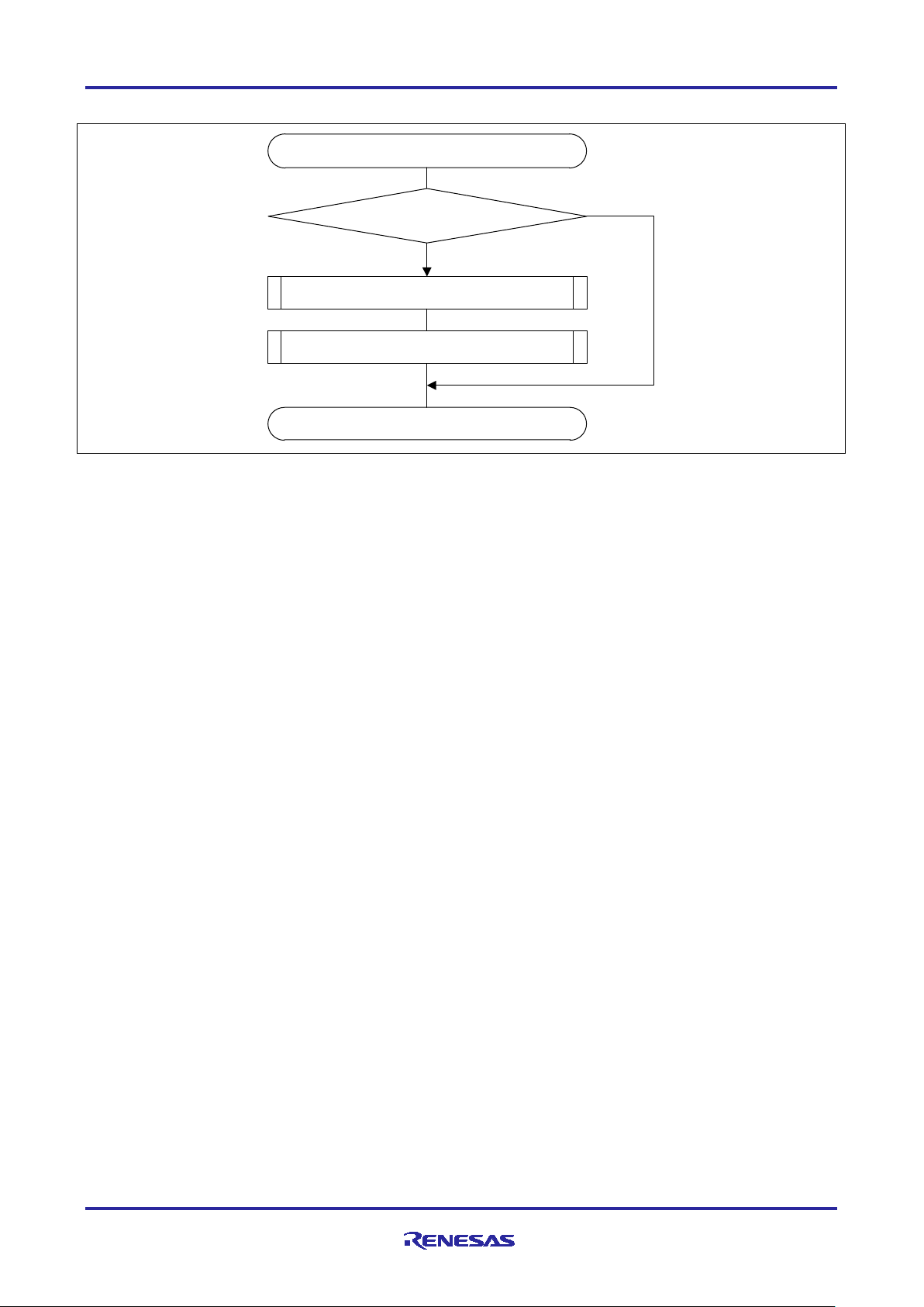
1-ms interrupt handling
Run mode
?
End
No
Set rotation direction
Yes
Normal mode
?
Normal control
Startup control
Slip speed gain calculation
No
Yes
3.6.3 1-ms Interrupt Handling
Figure 3.6 1-ms Interrupt Handling
R01AN4673EJ0110 Rev.1.10 Page 38 of 45
Apr 21, 21
Page 39
RX66T Implementation
Vector Control of Three-Phase Induction
Motor Used in Driving a Fan
Group interrupt including
overcurrent detection as a source
End
Motor stop processing
Release the high-impedance state
Overcurrent detected?
No
Yes
3.6.4 Handling of Group Interrupt that Includes Overcurrent Detection as a Source
Figure 3.7 Handling of Group Interrupt that Includes Overcurrent Detection as a Source
R01AN4673EJ0110 Rev.1.10 Page 39 of 45
Apr 21, 21
Page 40

RX66T Implementation
Vector Control of Three-Phase Induction
Motor Used in Driving a Fan
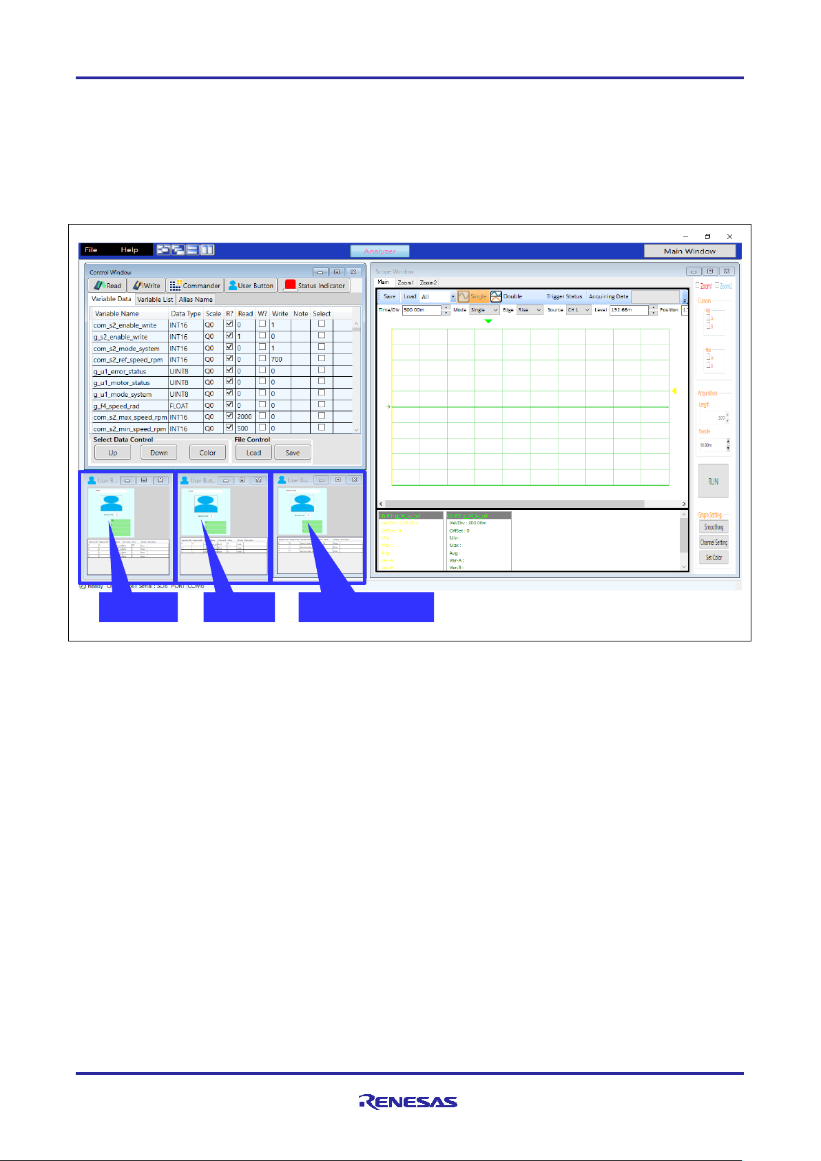
4. Development Support Tool “In Circuit Scope”
4.1 Overview
‘Renesas Motor Workbench 2.0’ is support tool for development of motor control system. ‘Renesas Motor
Workbench 2.0’ can be used with target software of this application note to analyze the control performance.
The user interfaces of ‘Renesas Motor Workbench 2.0’ provide functions like rotating start/stop command,
setting rotation speed command, etc…Please refer to ‘Renesas Motor Workbench 2.0 User’s Manual’ for
usage and more details.
Figure 4.1 Renesas Motor Workbench-Appearance
R01AN4673EJ0110 Rev.1.10 Page 40 of 45
Apr 21, 21
Page 41
RX66T Implementation
Vector Control of Three-Phase Induction
Motor Used in Driving a Fan
START
STOP
ERROR RESET
4.2 The Usage of RMW
Following shows how to use RMW to operate a motor. The RMW screen is shown in Figure 4.2. The screen
consists of three parts of the window. The control window is located in the upper left corner, the user button
is located int the lower left corner, and the scope window is located in the right side. In RMW, the user button
is used for basic operations, such as starting/stopping the motor. The function of each button is shown
below.
Figure 4.2 The Usage of RMW
4.2.1 START Button
The user button located on the left side is the START button. Use this button to set speed command value
and operate the motor. Enter the speed command value in rpm unit in the value column of
‘com_s2_ref_speed_rpm’. Then click the image part in the button to transition to the motor operating state
and accelerate to the set speed command value. However if errors occurred, the motor will not operating.
To change the motor rotation speed in the operating state, change the speed command value and click the
image part of the button to accelerate or decelerate the motor.
4.2.2 STOP Button
The user button located in the center is the STOP button. Click the image part in the button to switch to the
motor stop state.
4.2.3 ERROR RESET Button
The user button located in the right side is the ERROR RESET button. Click the image part in the button to
resets the error status.
R01AN4673EJ0110 Rev.1.10 Page 41 of 45
Apr 21, 21
Page 42
RX66T Implementation
Vector Control of Three-Phase Induction
Motor Used in Driving a Fan
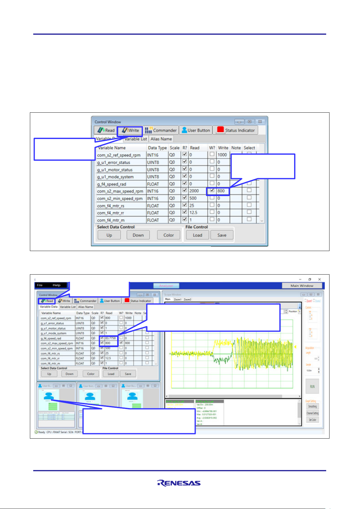
Step1
Write the desired value
Step2
Step3
Press the read button to read the current value and
Step4
Press the read button
4.2.4 Change Parameter Setting
The following is an example using RMW to change maximum speed value. The procedure for changing
parameters are shown in Figure 4.3 and Figure 4.4. The same procedure is used to change the other
parameters.
To set and write parameters as shown in steps 1 and 2 in Figure 4.3. When the START button is pressed to
operate the motor, the set parameters are reflected in the motor control layer variables. Figure 4.4 shows.
The result when the speed command is set to 1000rpm. Although the speed command value is set to
1000rpm, the maximum speed is limited to 800rpm.
Press the write button
Put a check mark
Figure 4.3 Setting parameters
confirm the motor speed is limited by the maximum
speed value(800rpm = 83.7758 rad/s).
Set the speed command value to 1000rpm,
Press START button (Reflect parameter)
Figure 4.4 Parameter reflection confirmation
R01AN4673EJ0110 Rev.1.10 Page 42 of 45
Apr 21, 21
Page 43

RX66T Implementation
Vector Control of Three-Phase Induction
Motor Used in Driving a Fan
RMW Variable
Type
Usage
(Motor Control Layer Variable)
4.3 RMW Variables
Table 4.1 lists the variables for use with the RMW. Note that modifications to these variables will not be
reflected in the motor control layer variables at the point these RMW variables are modified. The motor
control layer variables are written and modified at the point the value of g_s2_enable_write is written to
com_s2_enable_write.
Table 4.1 RMW Variables
Target Variable
com_s2_mode_system int16 State management
0: Stop mode
1: Run mode
3: Reset
Com_s2_direction int16 Rotational direction g_u1_dir_buff
com_s2_ref_speed_rpm int16 Speed command g_f4_ref_speed_rad
com_f4_kp_speed float32 Speed PI control proportional gain g_f4_kp_speed
com_f4_ki_speed float32 Speed PI control integral gain g_f4_ki_speed
com_f4_kp_iq float32 δ axis current PI control proportional gain g_f4_kp_iq
com_f4_ki_iq float32 δ axis current PI control integral gain g_f4_ki_iq
com_f4_speed_lpf_k float32 Speed LPF gain g_f4_speed_lpf_k
com_f4_current_lpf_k float32 Current LPF gain g_f4_current_lpf_k
com_f4_mtr_rs float32 Stator resistance mtr_p.f4_mtr_rs
com_f4_mtr_rr float32 Rotor resistance mtr_p.f4_mtr_rr
com_f4_mtr_m float32 Magnetizing inductance mtr_p.f4_mtr_m
com_f4_mtr_lls float32 Stator leakage resistance mtr_p.f4_mtr_ls
com_f4_mtr_llr float32 Rotor leakage inductance mtr_p.f4_mtr_lr
com_f4_offset_lpf_k float32 Current offset LPF gain g_f4_offset_lpf_k
com_s2_max_speed_rpm int16 Maximum speed g_f4_max_speed_rad
com_s2_min_speed_rpm int16 Minimum speed g_f4_min_speed_rad
com_f4_ctrl_ref_id float32 γ axis current command g_f4_ctrl_ref_id
com_f4_boot_id_up_time float32 Rise time at γ axis current startup g_f4_boot_id_up_step
com_f4_id_const_time float32 γ axis current/flux stabilization wait time g_f4_id_const_time
com_f4_accel float32 Rotational frequency command
acceleration step size
com_f4_fluctuation_limit float32 Speed fluctuation limit g_f4_fluctuation_limit
com_f4_offset_calc_time float32 Current offset adjustment time g_f4_offset_calc_time
com_f4_delay float32 Voltage output delay compensation
coefficient
com_f4_voltage_drop float32 Voltage drop correction threshold g_f4_voltage_drop
com_f4_voltage_drop_k float32 Voltage drop correction gain g_f4_voltage_drop_k
com_s2_enable_write int16 Variable write enable —
This variable’s value is reflected in
g_s2_mode_system at the point it is written.
g_f4_accel
g_f4_angle_compensation
R01AN4673EJ0110 Rev.1.10 Page 43 of 45
Apr 21, 21
Page 44

RX66T Implementation
Vector Control of Three-Phase Induction
Motor Used in Driving a Fan
Website and Support
Renesas Electronics Website
http://www.renesas.com/
Inquiries
http://www.renesas.com/contact/
All trademarks and registered trademarks are the property of their respective owners.
R01AN4673EJ0110 Rev.1.10 Page 44 of 45
Apr 21, 21
Page 45

RX66T Implementation
Vector Control of Three-Phase Induction
Motor Used in Driving a Fan
Rev.
Date
Description
Page
Summary
1.00
Aug 31, 20
—
First edition issued
1.10
Apr 21, 21
4
Updated version of CS+ to 8.05.00
27
Updated Table 3.7 List of Macro Definitions (3/12)
31
Updated Table 3.7 List of Macro Definitions (7/12)
Revision History
R01AN4673EJ0110 Rev.1.10 Page 45 of 45
Apr 21, 21
Page 46

General Precautions in the Handling of Microprocessing Unit and Microcontroller Unit Products
The following usage notes are applicable to all Microprocessing unit and Microcontroller unit products from Renesas. For detailed usage notes on the
products covered by this document, refer to the relevant sections of the document as well as any technical updates that have been issued for the products.
1. Precaution against Electrostatic Discharge (ESD)
A strong electrical field, when exposed to a CMOS device, can cause destruction of the gate oxide and ultimately degrade the device operation. Steps
must be taken to stop the generation of static electricity as much as possible, and quickly dissipate it when it occurs. Environmental control must be
adequate. When it is dry, a humidifier should be used. This is recommended to avoid using insulators that can easily build up static electricity.
Semiconductor devices must be stored and transported in an anti-static container, static shielding bag or conductive material. All test and
measurement tools including work benches and floors must be grounded. The operator must also be grounded using a wrist strap. Semiconductor
devices must not be touched with bare hands. Similar precautions must be taken for printed circuit boards with mounted semiconductor devices.
2. Processing at power-on
The state of the product is undefined at the time when power is supplied. The states of internal circuits in the LSI are indeterminate and the states of
register settings and pins are undefined at the time when power is supplied. In a finished product where the reset signal is applied to the external reset
pin, the states of pins are not guaranteed from the time when power is supplied until the reset process is completed. In a similar way, the states of pins
in a product that is reset by an on-chip power-on reset function are not guaranteed from the time when power is supplied until the power reaches the
level at which resetting is specified.
3. Input of signal during power-off state
Do not input signals or an I/O pull-up power supply while the device is powered off. The current injection that results from input of such a signal or I/O
pull-up power supply may cause malfunction and the abnormal current that passes in the device at this time may cause degradation of internal
elements. Follow the guideline for input signal during power-off state as described in your product documentation.
4. Handling of unused pins
Handle unused pins in accordance with the directions given under handling of unused pins in the manual. The input pins of CMOS products are
generally in the high-impedance state. In operation with an unused pin in the open-circuit state, extra electromagnetic noise is induced in the vicinity of
the LSI, an associated shoot-through current flows internally, and malfunctions occur due to the false recognition of the pin state as an input signal
become possible.
5. Clock signals
After applying a reset, only release the reset line after the operating clock signal becomes stable. When switching the clock signal during program
execution, wait until the target clock signal is stabilized. When the clock signal is generated with an external resonator or from an external oscillator
during a reset, ensure that the reset line is only released after full stabilization of the clock signal. Additionally, when switching to a clock signal
produced with an external resonator or by an external oscillator while program execution is in progress, wait until the target clock signal is stable.
6. Voltage application waveform at input pin
Waveform distortion due to input noise or a reflected wave may cause malfunction. If the input of the CMOS device stays in the area between V
(Max.) and V
input level is fixed, and also in the transition period when the input level passes through the area between V
7. Prohibition of access to reserved addresses
Access to reserved addresses is prohibited. The reserved addresses are provided for possible future expansion of functions. Do not access these
addresses as the correct operation of the LSI is not guaranteed.
8. Differences between products
Before changing from one product to another, for example to a product with a different part number, confirm that the change will not lead to problems.
The characteristics of a microprocessing unit or microcontroller unit products in the same group but having a different part number might differ in terms
of internal memory capacity, layout pattern, and other factors, which can affect the ranges of electrical characteristics, such as characteristic values,
operating margins, immunity to noise, and amount of radiated noise. When changing to a product with a different part number, implement a system-
evaluation test for the given product.
(Min.) due to noise, for example, the device may malfunction. Take care to prevent chattering noise from entering the device when the
IH
(Max.) and VIH (Min.).
IL
IL
Page 47

Corporate Headquarters
Contact information
www.renesas.com
Trademarks
of their respective owners.
Notice
1. Descriptions of circuits, software and other related information in this document are provided only to illustrate the operation of semiconductor products
and application examples. You are fully responsible for the incorporation or any other use of the circuits, software, and information in the design of your
product or system. Renesas Electronics disclaims any and all liability for any losses and damages incurred by you or third parties arising from the use
of these circuits, software, or information.
2. Renesas Electronics hereby expressly disclaims any warranties against and liability for infringement or any other claims involving patents, copyrights,
or other intellectual property rights of third parties, by or arising from the use of Renesas Electronics products or technical information described in this
document, including but not limited to, the product data, drawings, charts, programs, algorithms, and application examples.
3. No license, express, implied or otherwise, is granted hereby under any patents, copyrights or other intellectual property rights of Renesas Electronics
or others.
4. You shall be responsible for determining what licenses are required from any third parties, and obtaining such licenses for the lawful import, export,
manufacture, sales, utilization, distribution or other disposal of any products incorporating Renesas Electronics products, if required.
5. You shall not alter, modify, copy, or reverse engineer any Renesas Electronics product, whether in whole or in part. Renesas Electronics disclaims any
and all liability for any losses or damages incurred by you or third parties arising from such alteration, modification, copying or reverse engineering.
6. Renesas Electronics products are classified according to the following two quality grades: “Standard” and “High Quality”. The intended applications for
each Renesas Electronics product depends on the product’s quality grade, as indicated below.
"Standard": Computers; office equipment; communications equipment; test and measurement equipment; audio and visual equipment; home
"High Quality": Transportation equipment (automobiles, trains, ships, etc.); traffic control (traffic lights); large-scale communication equipment; key
Unless expressly designated as a high reliability product or a product for harsh environments in a Renesas Electronics data sheet or other Renesas
Electronics document, Renesas Electronics products are not intended or authorized for use in products or systems that may pose a direct threat to
human life or bodily injury (artificial life support devices or systems; surgical implantations; etc.), or may cause serious property damage (space
system; undersea repeaters; nuclear power control systems; aircraft control systems; key plant systems; military equipment; etc.). Renesas Electronics
disclaims any and all liability for any damages or losses incurred by you or any third parties arising from the use of any Renesas Electronics product
that is inconsistent with any Renesas Electronics data sheet, user’s manual or other Renesas Electronics document.
7. No semiconductor product is absolutely secure. Notwithstanding any security measures or features that may be implemented in Renesas Electronics
hardware or software products, Renesas Electronics shall have absolutely no liability arising out of any vulnerability or security breach, including but
not limited to any unauthorized access to or use of a Renesas Electronics product or a system that uses a Renesas Electronics product. RENESAS
ELECTRONICS DOES NOT WARRANT OR GUARANTEE THAT RENESAS ELECTRONICS PRODUCTS, OR ANY SYSTEMS CREATED USING
RENESAS ELECTRONICS PRODUCTS WILL BE INVULNERABLE OR FREE FROM CORRUPTION, ATTACK, VIRUSES, INTERFERENCE,
HACKING, DATA LOSS OR THEFT, OR OTHER SECURITY INTRUSION (“Vulnerability Issues”). RENESAS ELECTRONICS DISCLAIMS ANY AND
ALL RESPONSIBILITY OR LIABILITY ARISING FROM OR RELATED TO ANY VULNERABILITY ISSUES. FURTHERMORE, TO THE EXTENT
PERMITTED BY APPLICABLE LAW, RENESAS ELECTRONICS DISCLAIMS ANY AND ALL WARRANTIES, EXPRESS OR IMPLIED, WITH
RESPECT TO THIS DOCUMENT AND ANY RELATED OR ACCOMPANYING SOFTWARE OR HARDWARE, INCLUDING BUT NOT LIMITED TO
THE IMPLIED WARRANTIES OF MERCHANTABILITY, OR FITNESS FOR A PARTICULAR PURPOSE.
8. When using Renesas Electronics products, refer to the latest product information (data sheets, user’s manuals, application notes, “General Notes for
Handling and Using Semiconductor Devices” in the reliability handbook, etc.), and ensure that usage conditions are within the ranges specified by
Renesas Electronics with respect to maximum ratings, operating power supply voltage range, heat dissipation characteristics, installation, etc. Renesas
Electronics disclaims any and all liability for any malfunctions, failure or accident arising out of the use of Renesas Electronics products outside of such
specified ranges.
9. Although Renesas Electronics endeavors to improve the quality and reliability of Renesas Electronics products, semiconductor products have specific
characteristics, such as the occurrence of failure at a certain rate and malfunctions under certain use conditions. Unless designated as a high reliability
product or a product for harsh environments in a Renesas Electronics data sheet or other Renesas Electronics document, Renesas Electronics
products are not subject to radiation resistance design. You are responsible for implementing safety measures to guard against the possibility of bodily
injury, injury or damage caused by fire, and/or danger to the public in the event of a failure or malfunction of Renesas Electronics products, such as
safety design for hardware and software, including but not limited to redundancy, fire control and malfunction prevention, appropriate treatment for
aging degradation or any other appropriate measures. Because the evaluation of microcomputer software alone is very difficult and impractical, you are
responsible for evaluating the safety of the final products or systems manufactured by you.
10. Please contact a Renesas Electronics sales office for details as to environmental matters such as the environmental compatibility of each Renesas
Electronics product. You are responsible for carefully and sufficiently investigating applicable laws and regulations that regulate the inclusion or use of
controlled substances, including without limitation, the EU RoHS Directive, and using Renesas Electronics products in compliance with all these
applicable laws and regulations. Renesas Electronics disclaims any and all liability for damages or losses occurring as a result of your noncompliance
with applicable laws and regulations.
11. Renesas Electronics products and technologies shall not be used for or incorporated into any products or systems whose manufacture, use, or sale is
prohibited under any applicable domestic or foreign laws or regulations. You shall comply with any applicable export control laws and regulations
promulgated and administered by the governments of any countries asserting jurisdiction over the parties or transactions.
12. It is the responsibility of the buyer or distributor of Renesas Electronics products, or any other party who distributes, disposes of, or otherwise sells or
transfers the product to a third party, to notify such third party in advance of the contents and conditions set forth in this document.
13. This document shall not be reprinted, reproduced or duplicated in any form, in whole or in part, without prior written consent of Renesas Electronics.
14. Please contact a Renesas Electronics sales office if you have any questions regarding the information contained in this document or Renesas
Electronics products.
(Note1) “Renesas Electronics” as used in this document means Renesas Electronics Corporation and also includes its directly or indirectly controlled
(Note2) “Renesas Electronics product(s)” means any product developed or manufactured by or for Renesas Electronics.
subsidiaries.
electronic appliances; machine tools; personal electronic equipment; industrial robots; etc.
financial terminal systems; safety control equipment; etc.
(Rev.5.0-1 October 2020)
TOYOSU FORESIA, 3-2-24 Toyosu,
Koto-ku, Tokyo 135-0061, Japan
Renesas and the Renesas logo are trademarks of Renesas Electronics
Corporation. All trademarks and registered trademarks are the property
For further information on a product, technology, the most up-to-date
version of a document, or your nearest sales office, please visit:
www.renesas.com/contact/.
© 2021 Renesas Electronics Corporation. All rights reserved.
 Loading...