

Page 1

Application Note
R-IN32M3 Module (RY9012A0)
R-IN32M3 Module Evaluation Board
Introduction
This document describes sample software for host microcomputers (RX66T) mounted on the R-IN32M3
Module Evaluation Board (SEM1320), which is manufactured by Shimafuji Electric Co., Ltd.
Target Device
RX66T (R5F566TKADFP)
R-IN32M3 Module (RY9012A0)
Contents
1. Overview ................................................................................................................................. 4
1.1 Overview .................................................................................................................................................. 4
1.2 Operating environment ............................................................................................................................ 5
2. Hardware configuration ............................................................................................................ 7
2.1 List of specifications ................................................................................................................................ 7
2.2 Appearance of the board ......................................................................................................................... 8
2.3 Block diagram .......................................................................................................................................... 9
2.4 Features ................................................................................................................................................ 10
2.4.1 Power supply ....................................................................................................................................... 10
2.4.2 GND ..................................................................................................................................................... 11
2.4.3 RESET and JTAG ............................................................................................................................... 12
2.4.4 R-IN32M3 Module ............................................................................................................................... 13
2.4.5 Emulator connection ............................................................................................................................ 13
2.5 External interfaces ................................................................................................................................. 14
2.5.1 Ethernet connector .............................................................................................................................. 14
2.5.2 LED ...................................................................................................................................................... 14
2.5.3 Switch .................................................................................................................................................. 16
2.5.4 Connector ............................................................................................................................................ 19
2.5.5 Jumper ................................................................................................................................................. 23
2.6 Difference between RX66T CPU Card .................................................................................................. 25
3. Sample software configuration ............................................................................................... 26
3.1 Folder structure ..................................................................................................................................... 26
3.1.1 Overview of the project ........................................................................................................................ 27
3.2 Setup of development environment....................................................................................................... 28
3.2.1 Install ................................................................................................................................................... 28
3.2.2 Connection .......................................................................................................................................... 31
R12AN0111EJ0204 Rev.2.04 Page 1 of 88
Apr.26.2021
Page 2

R-IN32M3 Module (RY9012A0) R-IN32M3 Module Evaluation Board
3.2.3 Import project ....................................................................................................................................... 33
3.2.4 FIT Module .......................................................................................................................................... 36
3.2.5 Build project ......................................................................................................................................... 41
3.2.6 Debug .................................................................................................................................................. 42
3.3 How to use ............................................................................................................................................. 43
3.3.1 I/O mirror response (via PROFINET) .................................................................................................. 43
3.3.2 I/O mirror response (via EtherNet/IP) .................................................................................................. 48
3.3.3 I/O mirror response (via EtherCAT)..................................................................................................... 52
3.3.4 Motor Sample (via PROFINET) ........................................................................................................... 57
3.3.5 Motor Sample (via EtherNet/IP) .......................................................................................................... 59
3.3.6 Motor control (via EtherCAT) ............................................................................................................... 61
3.3.7 Remote I/O (via PROFINET) ............................................................................................................... 63
3.3.8 Remote I/O (via EtherNet/IP) .............................................................................................................. 65
3.3.9 Remote I/O (via EtherCAT) ................................................................................................................. 67
3.4 Application Implement Guide ................................................................................................................ 70
3.4.1 PROFINET .......................................................................................................................................... 71
3.4.2 EtherNet/IP .......................................................................................................................................... 76
3.4.3 EtherCAT ............................................................................................................................................. 80
4. Appendix ............................................................................................................................... 85
4.1 GOAL API .............................................................................................................................................. 85
4.2 OS Service Call ..................................................................................................................................... 85
4.3 Motor Sample ........................................................................................................................................ 86
Revision History ............................................................................................................................ 87
R12AN0111EJ0204 Rev.2.04 Page 2 of 88
Apr.26.2021
Page 3
R-IN32M3 Module (RY9012A0) R-IN32M3 Module Evaluation Board
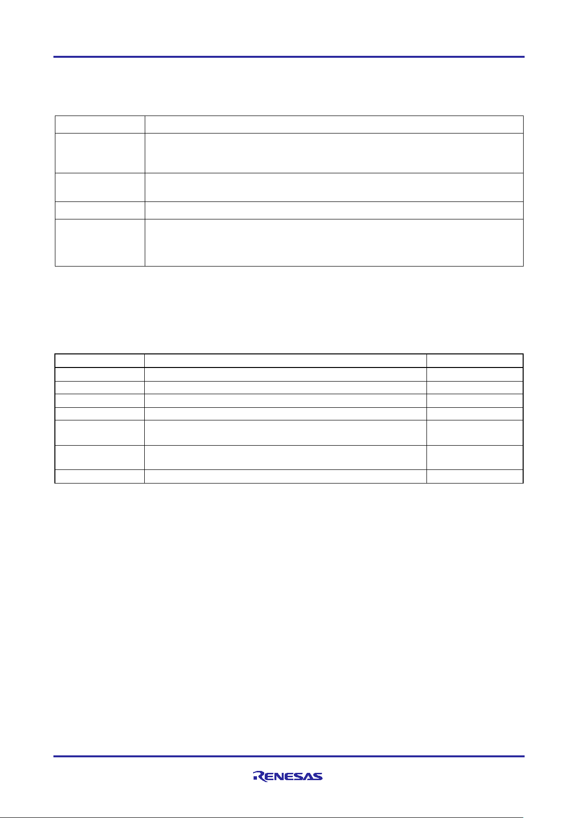
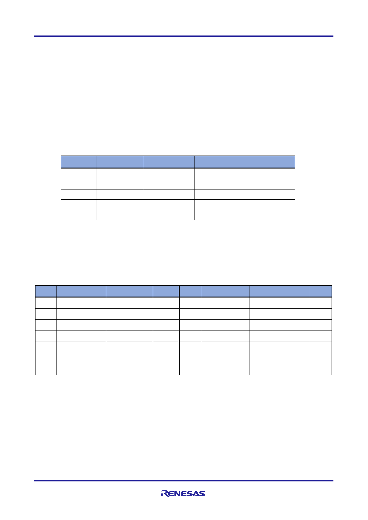
Terms
Description
This board
R-IN32M3 Module Evaluation Board: SEMB1320 (manufactured by Shimafuji Electric
This sample
The sample program for the host microcomputer (RX66T) that is explained in this
API
Application Programming Interface
GOAL
Generic Open Abstraction Layer
Document Type
Document Title
Document No.
Data Sheet
R-IN32M3 Module Datasheet
R19DS0109ED****
User’s Manual
R-IN32M3 Module User’s Manual: Hardware
R19UH0122ED****
User’s Manual
R-IN32M3 Module User’s Manual: Software
R17US0002ED****
Quick Start Guide
R-IN32M3 Module Application Note: Quick Start Guide
R12QS0042ED****
Application Note
Sensorless Vector Control for Permanent Magnet Synchronous
R01AN4244EJ****
User's Manual
Renesas Solution Starter Kit 24V Motor Control Evaluation
System for RX23T (Motor RSSK)
R20UT3697EJ****
Application Note
RX Smart Configurator User’s Guide: e² studio
R20AN0451ES****
List of Abbreviations and Acronyms
In this document, the terms below are defined as follows:
Co., Ltd.), which is the target board for the sample programs explained in this
document
software (SW)
document
See "R-IN32M3 Module User's Manual: Software API description”
(R17US0002ED****)』
Related documents
Motor (Implementation)
R12AN0111EJ0204 Rev.2.04 Page 3 of 88
Apr.26.2021
Page 4
R-IN32M3 Module (RY9012A0) R-IN32M3 Module Evaluation Board
1. Overview
1.1 Overview
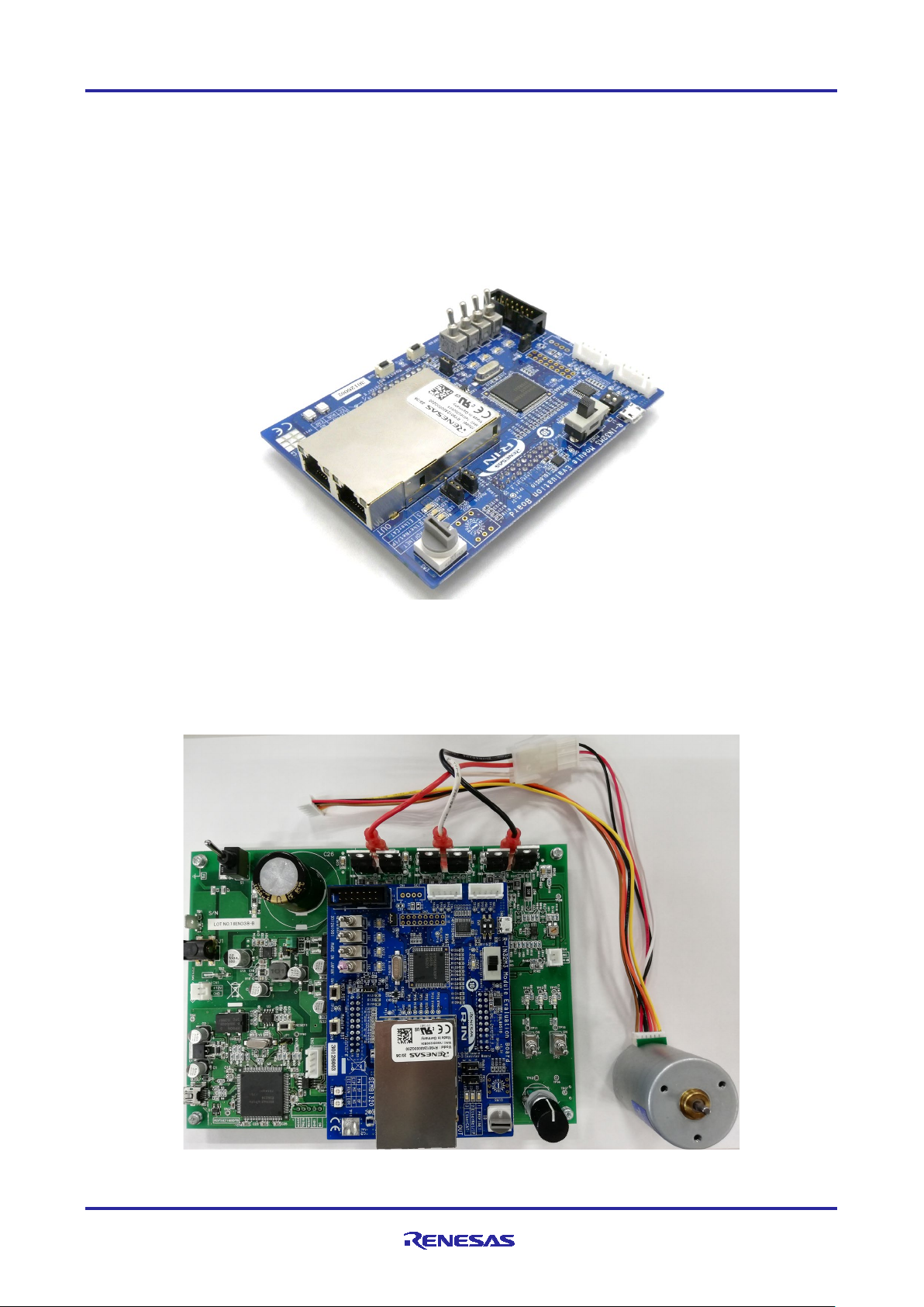
This document describes sample software for host microcomputers (RX66T) mounted on theR-IN32M3
Module Evaluation Board (SEMB1320), which is manufactured by Shimafuji Electric Co., Ltd.
RX66T is mounted on this board as the host microcomputer of the R-IN32M3 Module and communicate via
SPI.
Figure 1-1 R-IN32M3 Module Evaluation Board
This board can be connected to an optional inverter board, which is included in "24V Motor Control
Evaluation System for RX23T", to evaluate motor control by industrial Ethernet protocol communication.
Figure 1-2 Photos of this board connected to the Inverter Board
R12AN0111EJ0204 Rev.2.04 Page 4 of 88
Apr.26.2021
Page 5
R-IN32M3 Module (RY9012A0) R-IN32M3 Module Evaluation Board
Category
Name
Version
Link
Remarks
R-IN32M3
package
Sample
-
r18an0052xx0***
Integrated
e2studio
64bit version:
V7.8.0 or later
https://www.renesas.com/softwa
RX family
package
CC-RX
V3.03.00
https://www.renesas.com/softwa
Not necessary for OS
RX family
GCC for
RX
V8.3.0.202004
https://gcc-renesas.com/rx-
RX family real-
RI600V4
V1.06.00
https://www.renesas.com/softwa
family
Not necessary for OS
RX family
FreeRTOS
FreeRTOS
V10.0.04
https://www.renesas.com/softwa
Not necessary for OS
Management
ICE
V1.3.1 or later
-
port industrial
package
Software PLC
TwinCAT
V3.1
Beckhoff Automation
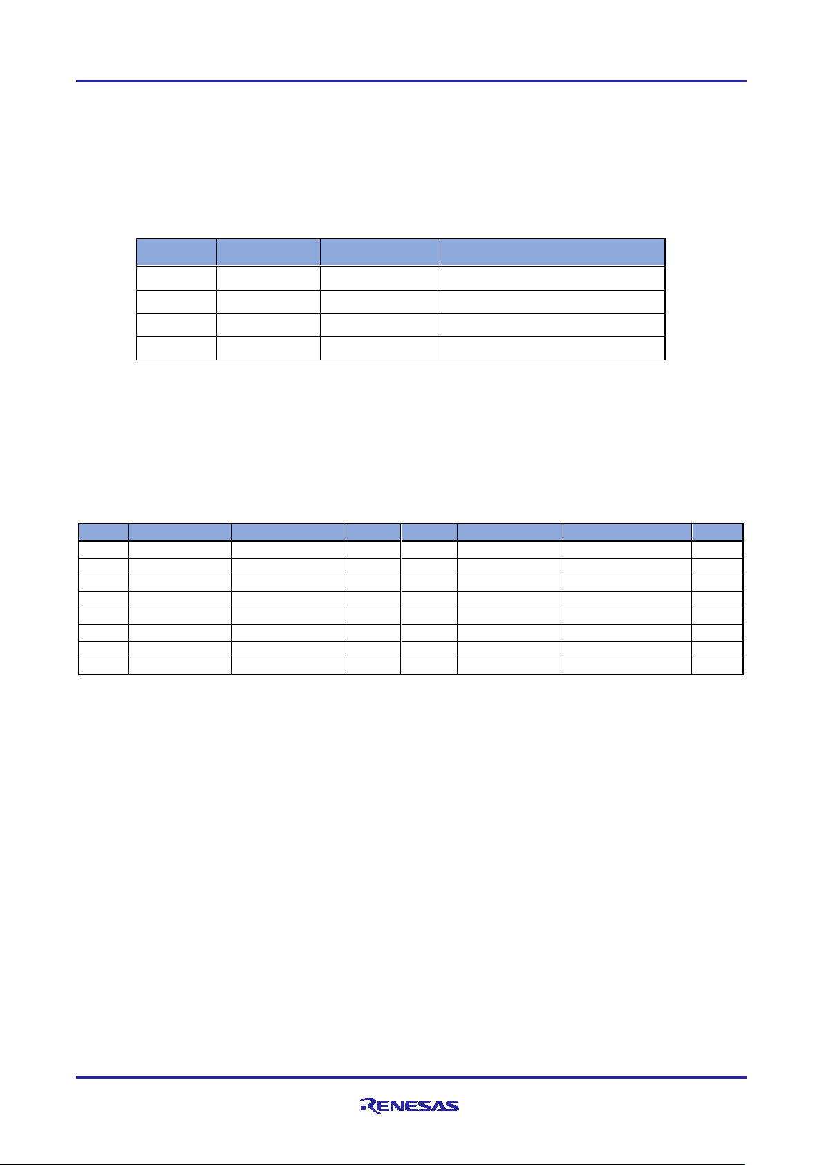
1.2 Operating environment
The operating environment of this sample software is shown in Table 1-1.
Table 1-1 Operating Environments
module
Sample
development
environment
C/C++
Compiler
GNU
Toolchain
time OS
Renesas
Tool, simple
software PLC
package
Renesas
2021-01 or later
32bit version:
re-tool/e-studio
re-tool/cc-compiler-package-rxfamily
download-toolchains
re-tool/ri600v4-real-time-os-rx-
re-tool/rx-family-renesas-freertos
less sample projects
less sample projects
less sample projects
automation GmbH
Including with Sample
of EtherCAT
GmbH
R12AN0111EJ0204 Rev.2.04 Page 5 of 88
Apr.26.2021
Page 6

R-IN32M3 Module (RY9012A0) R-IN32M3 Module Evaluation Board
Abbreviation
Name
Description
E1
E1 emulator
On-chip debugging emulator and flash programmer
Type name:R0E000010KCE00
E2 Lite
E2 emulator Lite
On-chip debugging emulator and flash programmer
Type name:RTE0T0002LKCE00000R
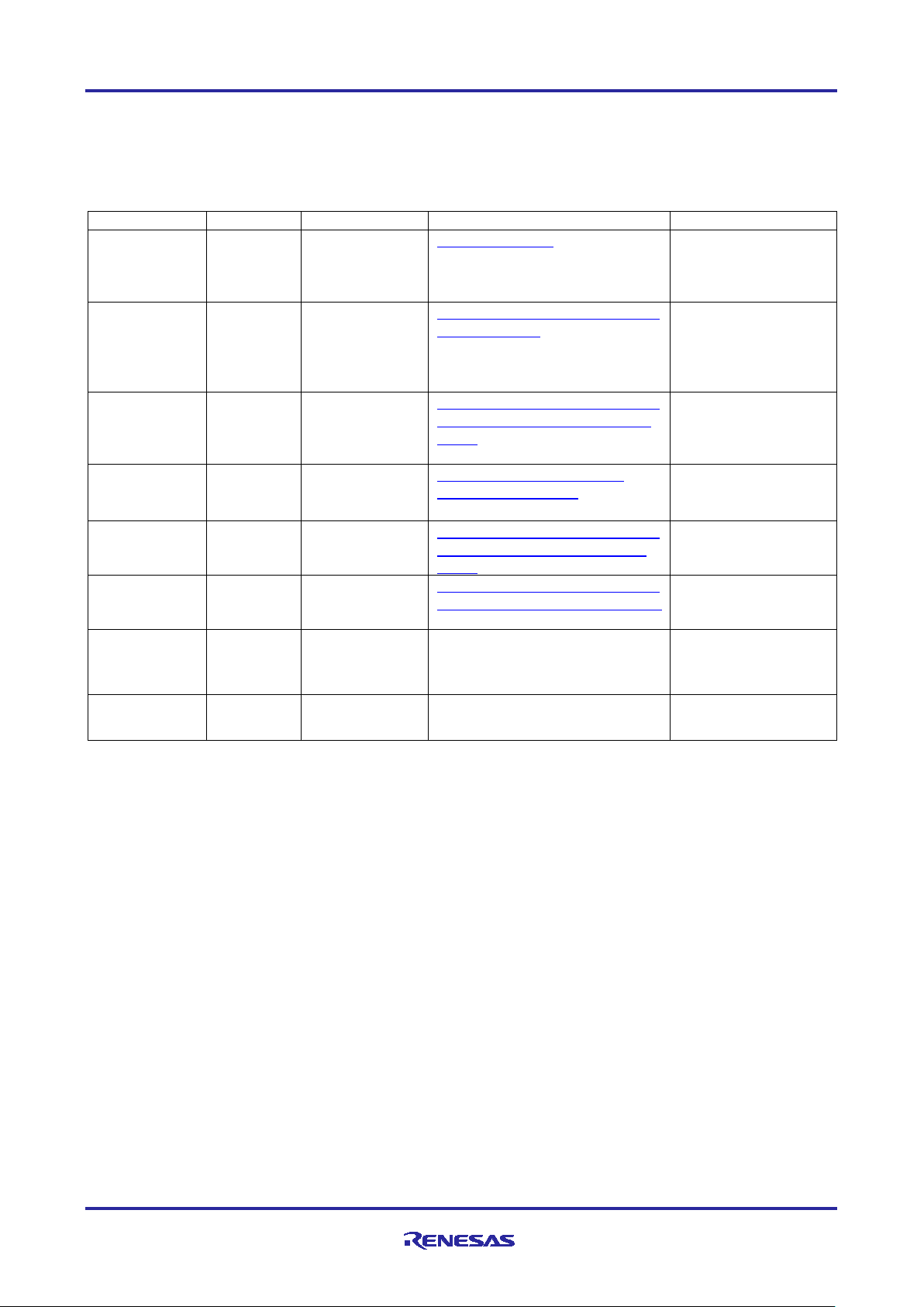
Product name
Type name
Link
24V Motor Control Evaluation
RTK0EM0006S01212BJ
https://www.renesas.com/products/
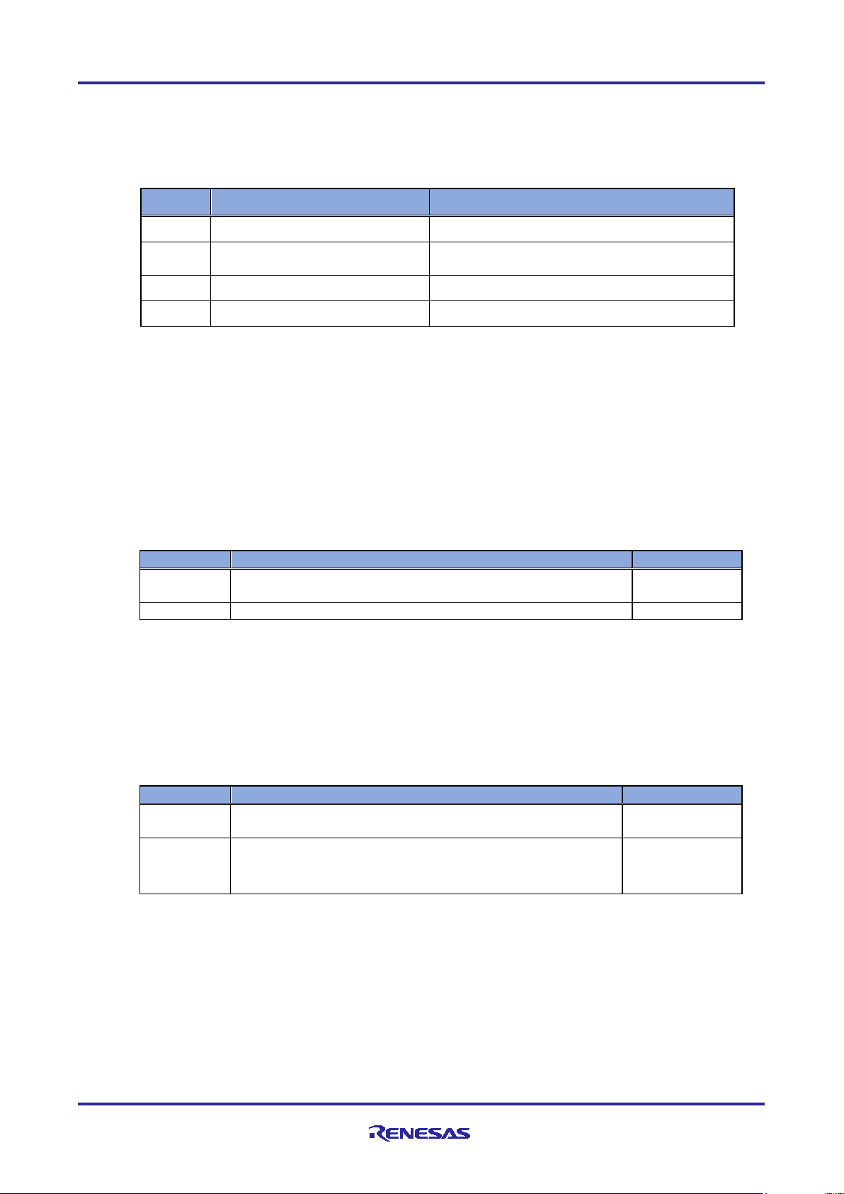
One of the following emulators is required separately to run this sample software.
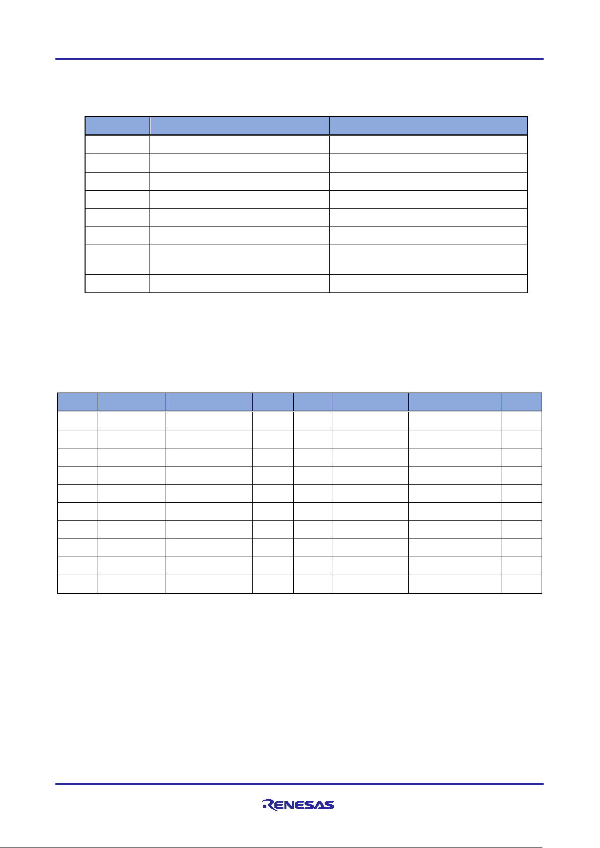
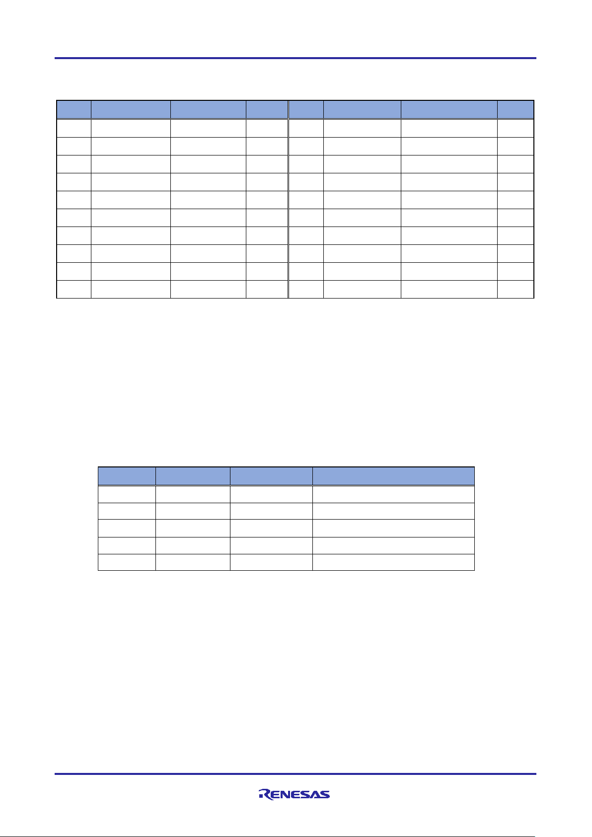
Table 1-2 Supported emulators
To execute the motor control samples included in this sample software, a 24V inverter board included below,
and a BLDC motor are required. In addition, a separate DC24V stabilized power supply is required.
Table 1-3 Corresponding motor control board
System for RX23T
R12AN0111EJ0204 Rev.2.04 Page 6 of 88
Apr.26.2021
Page 7

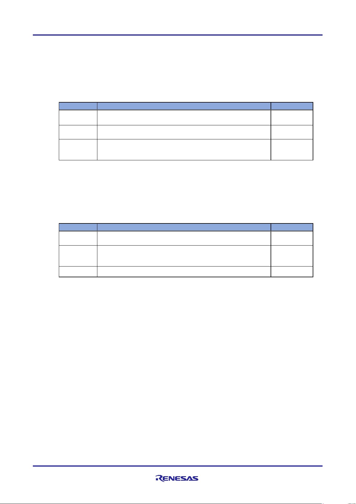
R-IN32M3 Module (RY9012A0) R-IN32M3 Module Evaluation Board
Item
Functions and specification
5V (Supply from USB Micro B or inverter board.)
or 3.3V (from inverter board)
Flash memory
1MB
Data flash memory
32KB
MCU Input Clock
Oscillator
8MHz
E1 / E2 Lite emulator
2.54mm pitch 14pins
CNA:2.54mm pitch 20pins
CNB:2.54mm pitch 20pins
Hall sensor
B5B-XH-A
Encoder
B5B-XH-A
SCI
B4B-XH-A (not mounted)
Power input switch
DIP switch 2bit
rotary switch Hexadecimal (not mounted)
EtherCAT ID
rotary switch Hexadecimal
CPU Reset
Push switch 1bit
R-IN32M3 Module Reset
Push switch 1bit
5V power in
Red 1bit
Generic
Green 4bit
Protocol display
Green 3bit
Protocol status
Bi-Color(2bit) x 2
Pin Headers for External Extensions
2.54mm pitch 16 pins (not mounted)
while executing motor program
60mA typ.
while executing ethernet
communication program
Operating Temperature
0 ~ 45℃
Board Dimension
80mm × 110mm t = 1.6mm
2. Hardware configuration
2.1 List of specifications
Table 2-1 shows a list of specifications for this board.
Table 2-1 Board specifications
Input Power Input voltage
Type name R5F566TKADFP
MCU
Connectors
Switches
LED
RAM 128KB
USB Micro B only input power (data line is not connected)
JTAG
Inverter Board
Slide switch SPDT
Generic
toggle switch 4bit
consumption
R12AN0111EJ0204 Rev.2.04 Page 7 of 88
Apr.26.2021
260mA typ.
Page 8
R-IN32M3 Module (RY9012A0) R-IN32M3 Module Evaluation Board
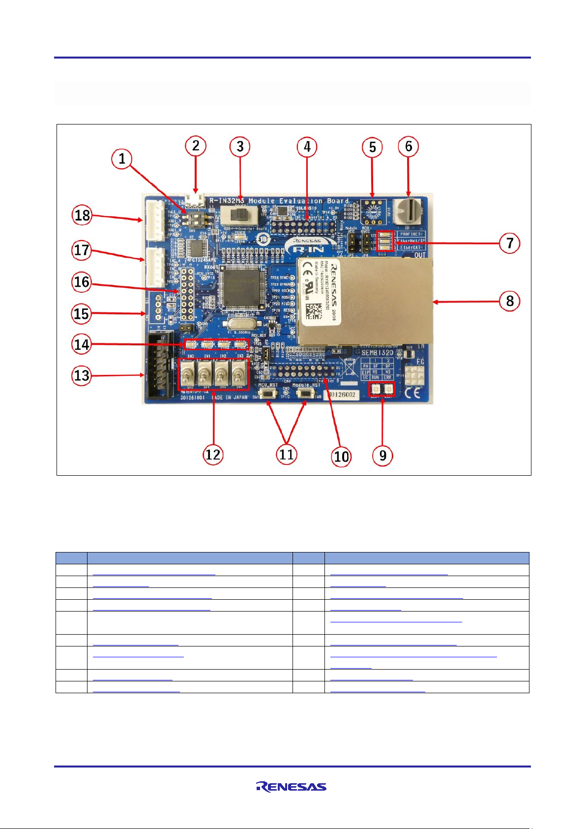
No.
Component Description
No.
Component Description
1
General purpose DIP switch
10
Inverter Board connector B
2
USB Micro B
11
Reset switch
3
Power input selector switch
12
General purpose toggle switch
4
Inverter Board connector A
13
JTAG connector
5
General-purpose rotary switch (not
mounted)
14
General purpose LED (Green)
6
EtherCAT ID switch
15
SCI connector (not mounted)
7
Protocol display LED
16
Pin header for external expansion (not
mounted)
8
R-IN32M3 Module
17
Encoder connector
9
Protocol status LED
18
Hall sensor connector
2.2 Appearance of the board
Figure 2-1 shows the appearance of this board, and Table 2-2 shows the main parts and external
interfaces.
Table 2-2
Main parts and external interfaces
Figure 2-1 Board appearance
R12AN0111EJ0204 Rev.2.04 Page 8 of 88
Apr.26.2021
Page 9
R-IN32M3 Module (RY9012A0) R-IN32M3 Module Evaluation Board
LED
3bit
0Ω
0Ω
MCU
RX66T
0Ω
User SW
DIP-SW
2bit
E1 Emulator
Connector
Jumper
General LED
LED
4bit
INV_+5VA
USB_+5VA
+3.3V
INV_VCC33_ A
MCU_UVC C
Module_VCC
+5V
UVCC
AVCC
General SW
Toggle SW
4bit
RX66T
100pin
Inverter Board
Connector B
Encoder
Connector
E1 Emulator
Connector
Hall Senso r
Connector
Protocol-display
UVCC
AVCC
Power Block
Logic Block
USB Micro-B
Connector
LED
2bit
Protocol Status
Reset
SW
R-IN32M3
Modu le
R-IN32M3
Modu le
Reserve
Rotary SW
4bit
(NMT)
SCI
Connector
(NMT)
Inverter Board B
Connector
Inverter Board A
Connector
Encoder
Connector
Hall-Sensor
Connector
LDO
3.3V/1A
Jumper
Jumper
Inverter Board
Connector A
EtherCAT-ID
Rotary SW
4bit
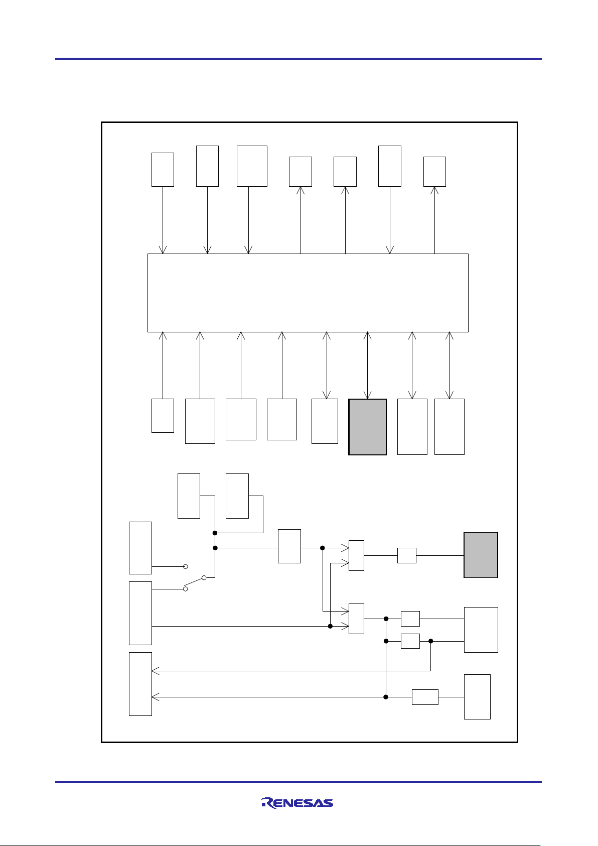
2.3 Block diagram
The block diagram of this board is shown below.
R12AN0111EJ0204 Rev.2.04 Page 9 of 88
Figure 2-2 Block diagram
Apr.26.2021
Page 10
R-IN32M3 Module (RY9012A0) R-IN32M3 Module Evaluation Board
CN8
USB Micro B
CN1
Inverter Board
CNA
SW7
3.3V
LDO
LED10
+5V
+3.3V
INV_+3.3V
19
20
15
16
MCU_UVCC
Module_VCC
JP5
JP4
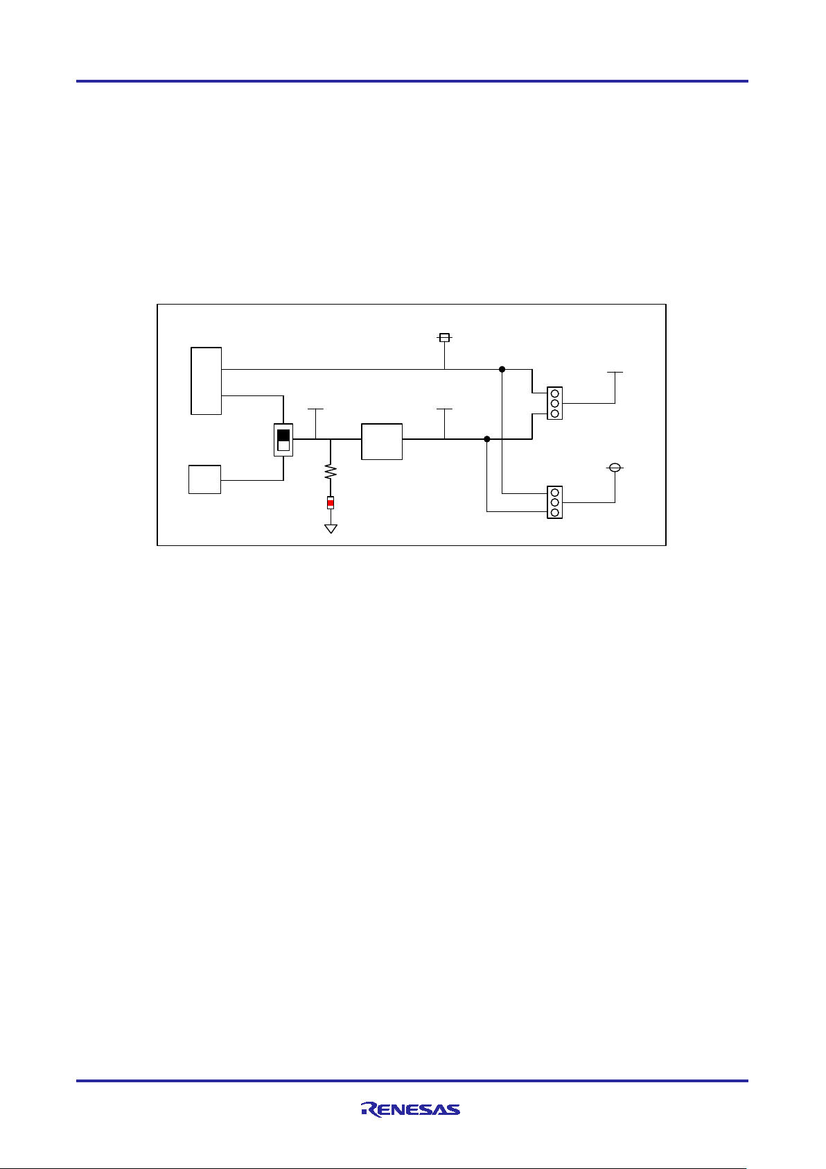
2.4 Features
2.4.1 Power supply
The board is powered by a USB Micro B connector or an Integer Board connector.
Normally, if you want to use this board alone, set SW7 at the USB Micro B connector side.
3.3V power supply method to RX66T MCU and the Module can be selected with jumper pins. For more
information, 2.5.5(3) JP4、2.5.5(4) JP5
Figure 2-3 shows power supply configuration diagram of this board.
Figure 2-3 Power diagram
R12AN0111EJ0204 Rev.2.04 Page 10 of 88
Apr.26.2021
Page 11
R-IN32M3 Module (RY9012A0) R-IN32M3 Module Evaluation Board
CN4
Inverter Board
CNB
4
19
20
PGAVSS1
GND1
GND2
5
IU
6
IV
7
IW
8
VPN
10
VU
11
VV
12
VW
15
VR1
GND
AVSS
PH0/AN007/PGAVSS0
AVSS
VSS
GND
P40/AN000
P41/AN001
P42/AN002
P43/AN003
P52/AN200
P53/AN201
P54/AN202
PH4/AN107/PGAVSS1
R39
0Ω
1MEGΩ
JP2
MCU
RX66T
U1
FG
GND
R-IN32M3
Module
U3
FG
GND
R69
(NM)
GND
TP11
(NM)
FG Terminal
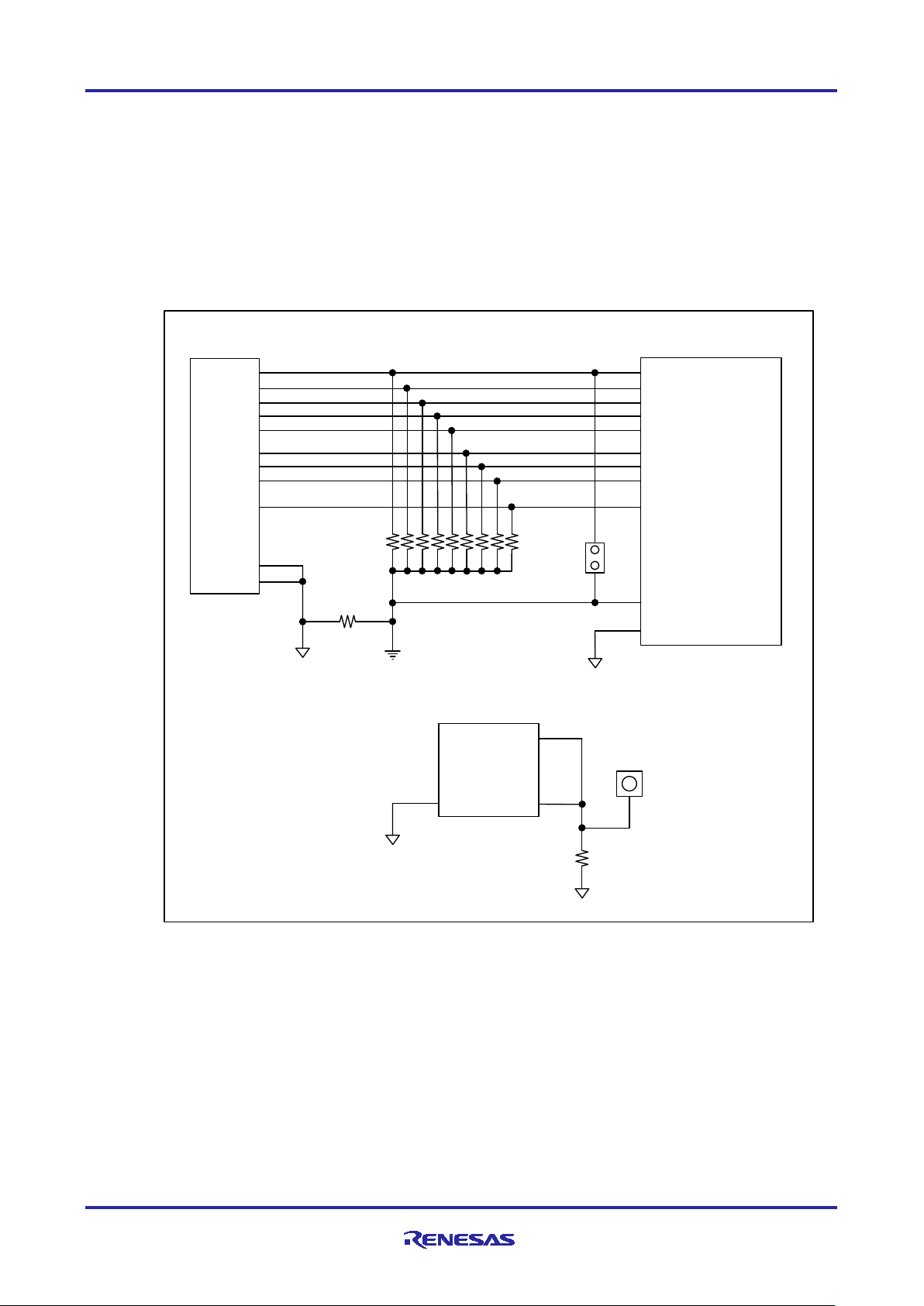
2.4.2 GND
The board's GND and AVSS are connected by R39 near CN4.
In the shipping state, JP2 is shorted, and the PGAVSS0 terminal of the MCU is connected to the AVSS.
The FG terminal of the R-IN32M3 Module is connected to the TP11 and can be connected to the GND by
mounting R69.
The connection diagram of the GND of this board is shown below.
R12AN0111EJ0204 Rev.2.04 Page 11 of 88
Apr.26.2021
Figure 2-4 GND
Page 12
R-IN32M3 Module (RY9012A0) R-IN32M3 Module Evaluation Board
CN1
JTAG
Connector
1
2
3
4
5
6
7
8
9
10
11
12
13
14
JP3
MCU_UVCC
MCU_UVCC
MCU
RX66T
U1
TCK
TRST#
EMLE
TDO/TXD
MD/FINED
TMS
UB
TDI/RXD
RESET#
MCU_UVCC
Module
_RESET#
RESET
IC
Module_VCC
RESET#
SW8
SW1
R-IN32M3
Module
U3
Module_VCC
VCC
2.4.3 RESET and JTAG
This board has three method of reset, "Power ON Reset", "Reset by JTAG Emulator", and "Reset by
External Switch". The reset and JTAM diagram of this board shows in Figure 2-5
Figure 2-5 RESET diagram
R12AN0111EJ0204 Rev.2.04 Page 12 of 88
Apr.26.2021
Page 13
R-IN32M3 Module (RY9012A0) R-IN32M3 Module Evaluation Board
U3
R-IN32M3
Module
SS#
MISO
MOSI
SCLK
SYNC0
SYNC1
MCU
RX66T
U1
PA3
PD1/SMISO8
PD2/SCK8
PD0/SMOSI8
PB6/IRQ2
PB3/IRQ9
SCLK
MOSI
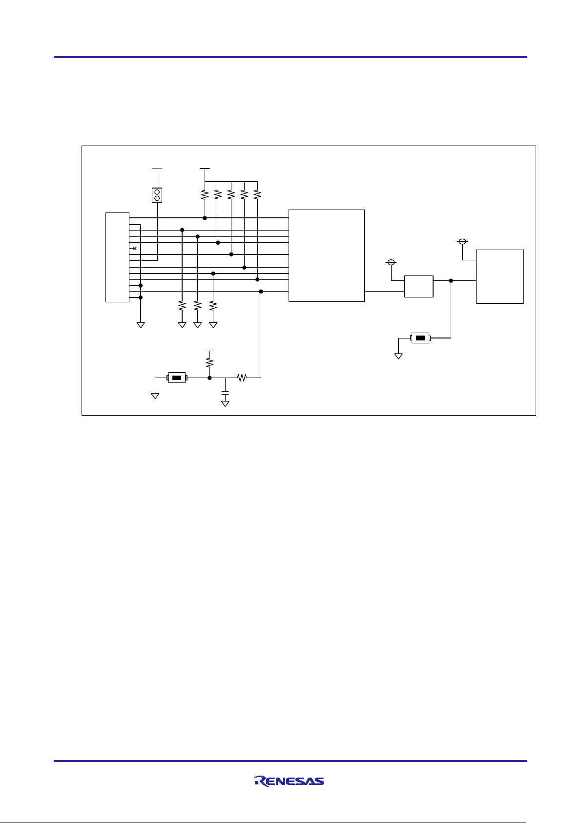
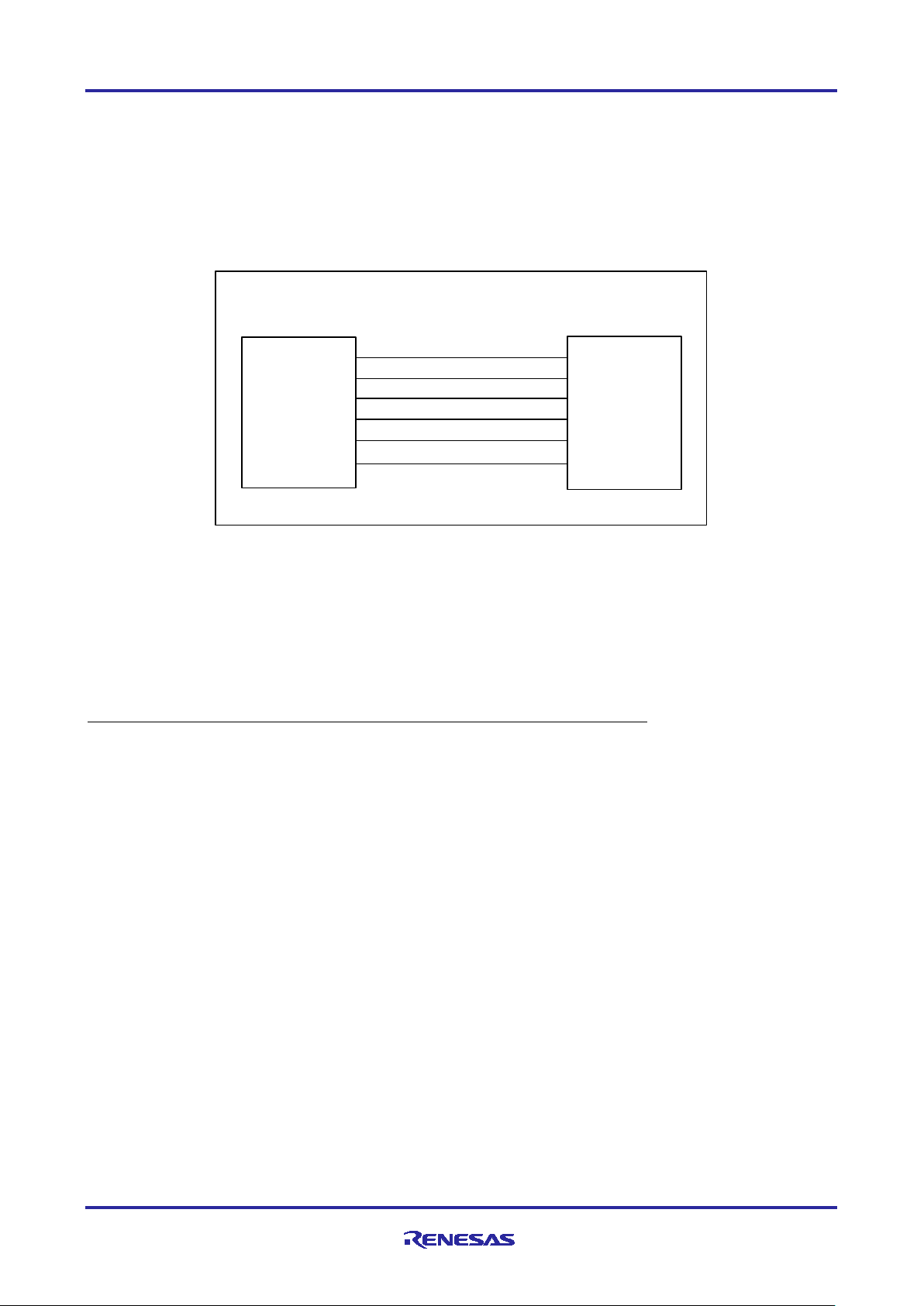
2.4.4 R-IN32M3 Module
For more information about the R-IN32M3 Module mounted on this board, see the R-IN32M3 Module User's
Manual Hardware Edition (R19UH0122EJ****).
The communication between the R-IN32M3 Module and the MCU is done via 4-wire SPI.
The SPI connection is shown in Figure 2-6. Each signal line in the SPI is not processed on this board
because a Pull-Up or Pull-Down resistor is granted in the R-IN32M3 Module.
Figure 2-6 SPI
2.4.5 Emulator connection
The RX66T program is rewritten using E1 or E2 Lite, an on-chip debugging emulator from Renesas
Electronics. The program is written by connecting E1 or E2 Lite to the Emulator connector on this board and
the USB on PC.
Do not supply power from E1, E2 Lite in the integrated development environment.
R12AN0111EJ0204 Rev.2.04 Page 13 of 88
Apr.26.2021
Page 14
R-IN32M3 Module (RY9012A0) R-IN32M3 Module Evaluation Board
protocol
MCU
RX66T
U1
P
94
P
95
LED
1
LED2 LED
3
MCU_
UVCC
P96
プトル表示
2.5 External interfaces
2.5.1 Ethernet connector
The R-IN32M3 Module on this board has two RJ45 network connectors.
The Ethernet switch function of the R-IN32M3 allows external connections in several network topologies,
such as dizzy chain connections. The internal PHY layer of R-IN32M3-EC can handle a variety of industrial
communication protocols and supports 10BASE-T and 100BASE-TX/FX.
2.5.2 LED
This board is equipped with a 5V power display LED, a protocol display LED, a protocol status LED
representing the status of each protocol, and a general-purpose output LED.
(1) 5V power display (LED10)
The LED10 (Red) is lit by a +5V power supply from the USB Micro B connector or the Inverter Board
connector. See Figure 2-3 for the configuration.
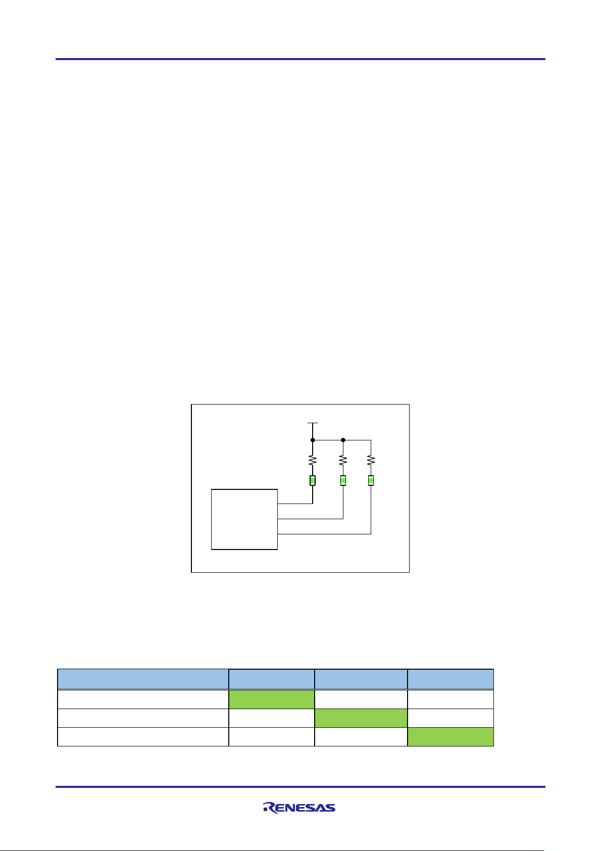
(2) Protocol display (LED1~3)
Depending on the industrial ethernet protocol selected, the project in the sample software is executed on
RX66T. Depending on the protocol running, one of LED1-3 (Green) will light up.
Figure 2-7 protocol display LED
LED display depending on the protocol is shown in Table 2-3.
Table 2-3 protocol display LED
PROFINET ON OFF OFF
LED1 (P94) LED2 (P95) LED3 (P96)
EtherNet/IP OFF ON OFF
EtherCAT OFF OFF ON
R12AN0111EJ0204 Rev.2.04 Page 14 of 88
Apr.26.2021
Page 15
R-IN32M3 Module (RY9012A0) R-IN32M3 Module Evaluation Board
GREEN
RED
GREEN
RED
PA0
PA1
PA2
PA4
DCP indicator
(Blink)
2
EtherNet/IP
NS
NS
MS
MS
3
EtherCAT
OFF
ERR
RUN
OFF
MCU
RX
66
T
U
1
PA2
PA4
LED4
MCU_UVCC
PA0
プ ト ルステ タス
PA1
Bi-Color
LED7
Bi-Color
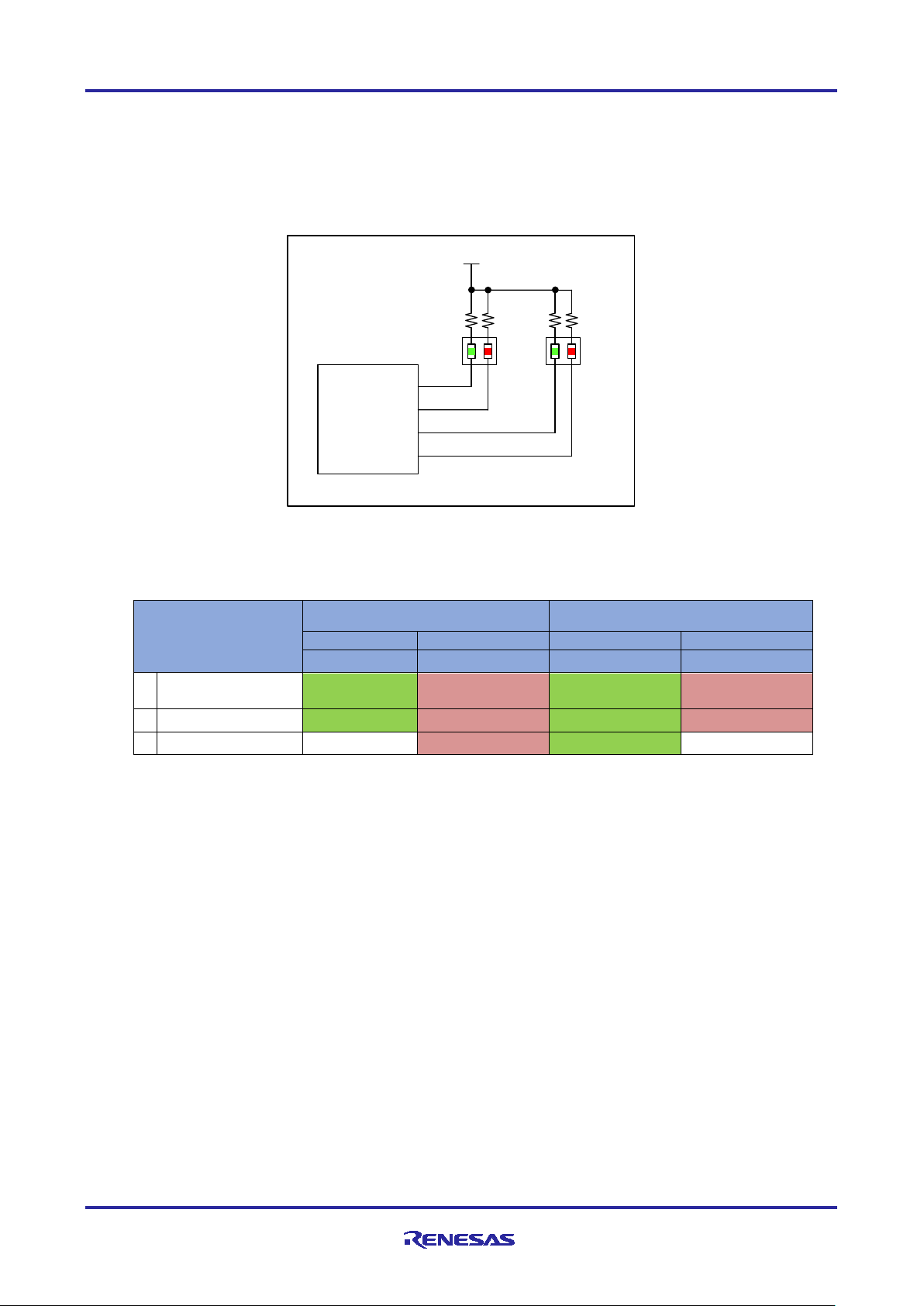
(3) Protocol status (LED4,7)
LED4 and LED7 are Bi-Color LEDs (Green / Red) that display the LED status specified in each protocol
standard.
For more information, see “R-IN32M3 Module User's Manual Software” (R17US0002ED****).
Figure 2-8 protocol status LED
Table 2-4 Protocol Status LED
LED7 LED4
Mode
1 PROFINET Connection BF
SF: system failure, BF: bus failure, DCP: discovery and configuration protocol
MS: module status indicator, NS: network status indicator,
SF
R12AN0111EJ0204 Rev.2.04 Page 15 of 88
Apr.26.2021
Page 16
R-IN32M3 Module (RY9012A0) R-IN32M3 Module Evaluation Board
EtherCAT Device ID
SW3
P93
P92
P91
P90
0 0 0 0 0 0 1 1 0 0 0 1 2 2 0 0 1 0 3 3 0 0 1 1 4 4 0 1 0 0 -
-
15 F 1 1 1
1
MCU
RX66
T
U
1
PE3
PE
4
LED
5
LED6
LED8
MCU_UVCC
PE1
Remote I/O LED
LED9
PE0
プトル切替スイッチ
1
2
4
8
COM
0
1
2
3
4
5
6
7
8
9
A
B
C
D
E
F
MCU
_
UVCC
MCU
RX66T
U1
P90
P91
P92
P93
SW3
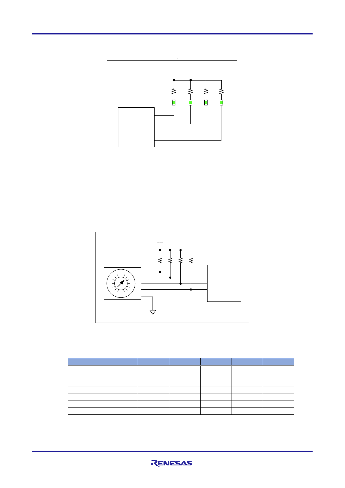
(4) General-purpose output LED (LED5,6,8,9)
4bit green LEDs (LED5, LED6, LED8, and LED9) are available for general purpose I/O applications.
Figure 2-9 General purpose LED
2.5.3 Switch
This board has several switches for EtherCAT Explicit Device ID, input for general-purpose I/O applications,
general-purpose DIP, input power, and resets.
(1) EtherCAT Explicit Device ID Switch (SW3)
When EtherCAT is selected as the protocol setting, the ID is set by SW3.
Figure 2-10 EtherCAT Explicit Device ID Switch
Table 2-5 EtherCAT ID setting
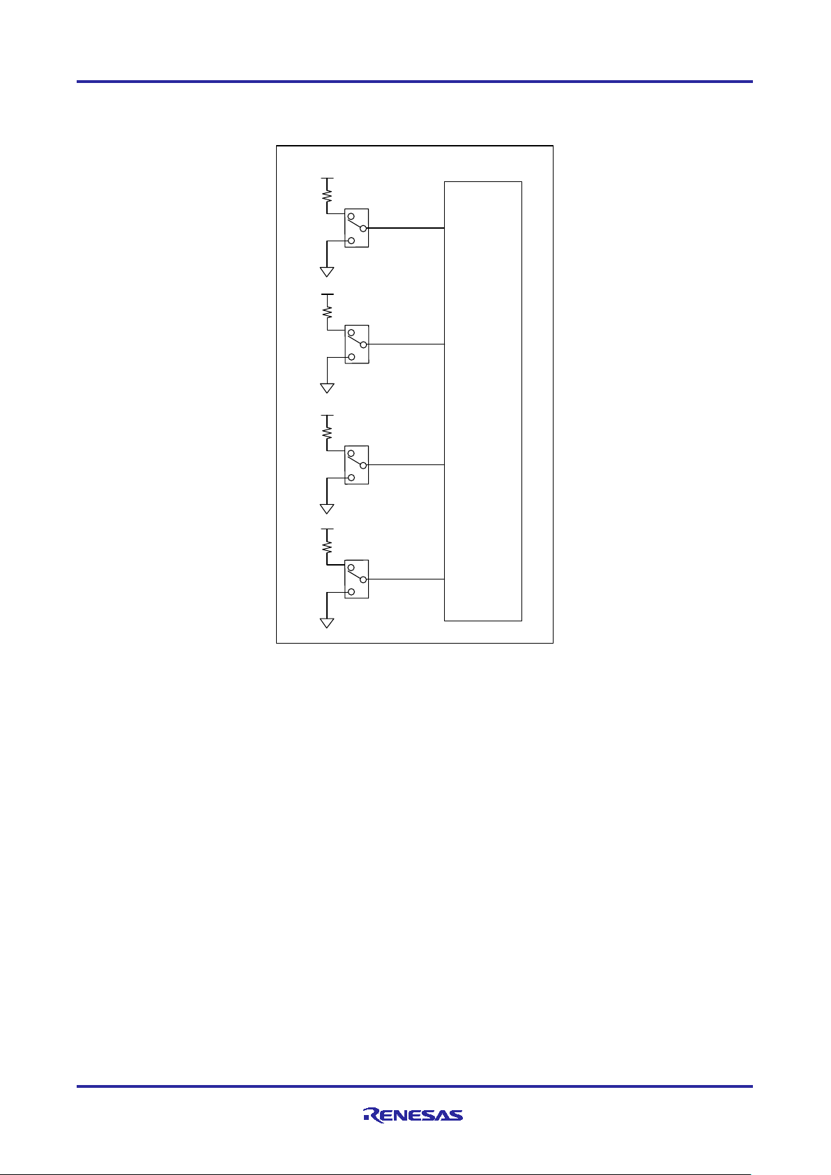
(2) General-purpose input SW (SW2,4,5,6)
SW2,4,5,6 (toggle switch) is available as an input switch for each 4bit for general purpose I/O applications.
R12AN0111EJ0204 Rev.2.04 Page 16 of 88
Apr.26.2021
Page 17
R-IN32M3 Module (RY9012A0) R-IN32M3 Module Evaluation Board
SW2
SW4
SW5
SW6
MCU
RX66T
U1
PB4
PB2
PB1
PB0
/ スイッチ
MCU_UVCC
MCU_UVCC
MCU_UVCC
MCU_UVCC
Figure 2-11 General purpose input SW
R12AN0111EJ0204 Rev.2.04 Page 17 of 88
Apr.26.2021
Page 18
R-IN32M3 Module (RY9012A0) R-IN32M3 Module Evaluation Board
SW7 Select
Description
1-2 ("USB" silkscreen side)
USB connector (CN8) supplies 5V power to this board
2-3 ("Inverter Board" silkscreen side)
5V power is supplied from the Integer Board connector A (CN1).
汎用
スイッチ
MCU_UVCC
MCU
RX66T
U1
P62
P63
SW9
ON
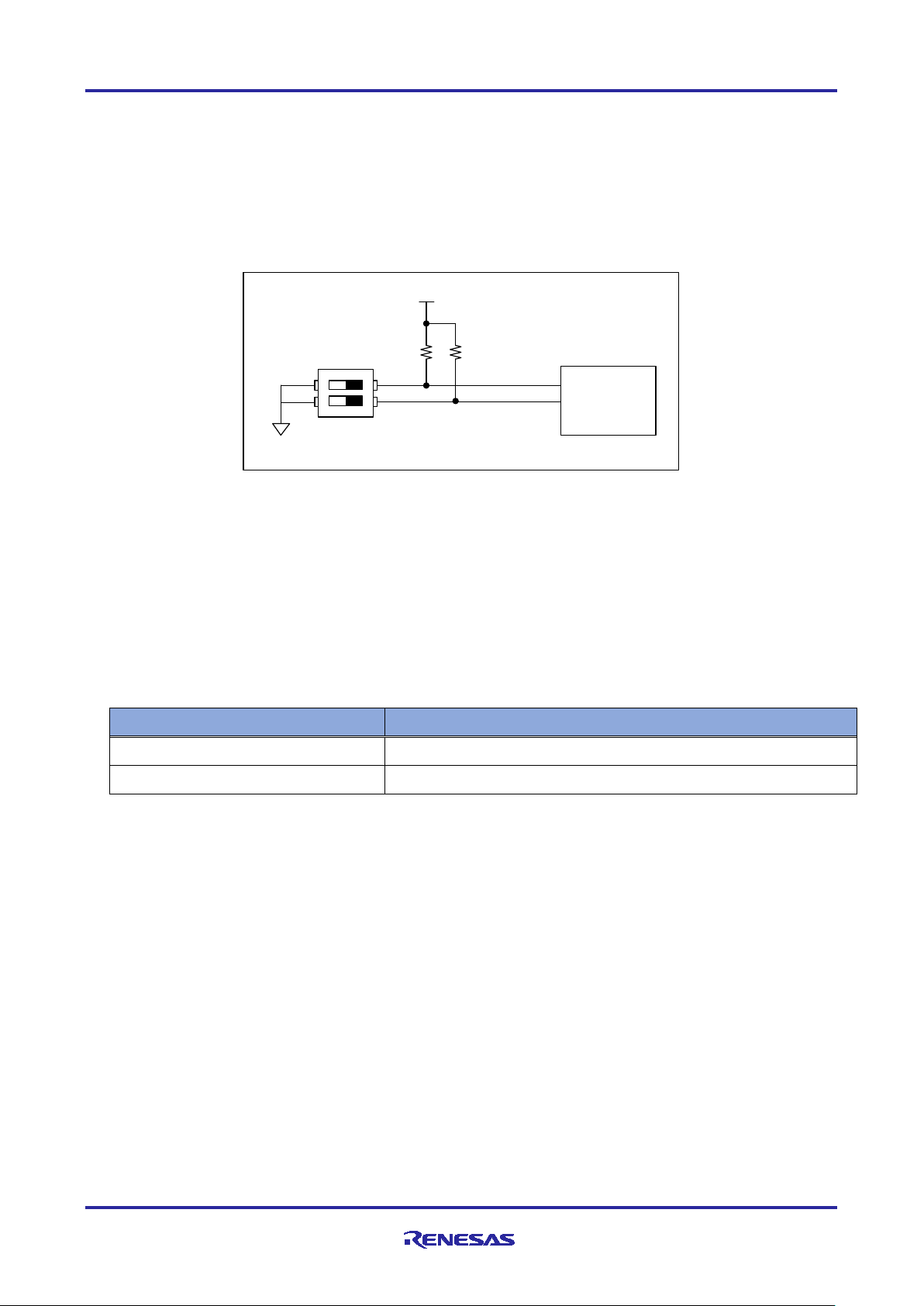
(3) General-input SW (SW9)
Figure 2-12 shows DIP switch, SW9, input for general purpose.
It is not used in this sample software.
Figure 2-12 Generic SW
(4) Power SW (SW7)
SW7 is a switch that selects the 5V power supply to this board. Select from the USB Micro B connector or
the Inverter Board connector to power it.
See Figure 2-3for the configuration.
Table 2-6 SW7
(5) Reset SW (SW1, SW8)
SW1 is push switch to reset the RX66T microcomputer and SW8 is one to reset the R-IN32M3 module.
See Figure 2-5 for reset configuration.
R12AN0111EJ0204 Rev.2.04 Page 18 of 88
Apr.26.2021
Page 19
R-IN32M3 Module (RY9012A0) R-IN32M3 Module Evaluation Board
CN
Type name
description
CN1
SFH11-PBPC-D10-ST-BK
Inverter Board connector A
CN2
B5B-XH-A
Hall sensor connector
CN3
B5B-XH-A
Encoder connector
CN4
SFH11-PBPC-D10-ST-BK
Inverter Board connector B
CN5
XG4C-1431
JTAG connector
CN6
B4B-XH-A (not mounted)
SCI connector (not mounted)
CN7
A1-16PA-2.54DSA (not mounted)
Pin Headers for External Extensions(not
CN8
10118194-0001LF
USB Micro B
pin
signal
MCU Port
Note
pin
signal
MCU Port
Note
1
LED1#
P22 2
LED2#
P21 3
LED3#
P20 4
VRL
P24 5
FO#
P70 6
NC - NC 7 WN
P76/ MTIOC4D
8 VN
P75/ MTIOC4C
9 UN
P74/ MTIOC3D
10
WP
P73/ MTIOC4B
11
VP
P72/ MTIOC4A
12
UP
P71/ MTIOC3B
13
SW1#
P23 14
SW2#
P27 15
+5VA1
- 16
+5VA2
- 17
GND
- 18
GND
- 19
VCC33_A1
- 20
VCC33_A2
-
2.5.4 Connector
Table 2-7 shows the connectors on this board (except for the RJ-45 connector with the R-IN32M3 Module).
Table 2-7 Connector List
mounted)
(1) Inverter Board Connector (CN1, CN4)
This board is equipped with an Inventor Board connector for use as a CPU card for "24V Motor Control
Evaluation System". The following is a pin assignment for the Integer Board connector:
Table 2-8 Inverter Board Connector A (CN1)
R12AN0111EJ0204 Rev.2.04 Page 19 of 88
Apr.26.2021
Page 20
R-IN32M3 Module (RY9012A0) R-IN32M3 Module Evaluation Board
pin
signal
MCU Port
Note
pin
signal
MCU Port
Note
1
AVCC1
- 2
AVCC2
- 3
NC - NC 4 PGAVSS1
PH0/ PGAVSS1
5 IU
P40/AN000
6 IV
P41/AN001
7 IW
P42/AN002
8 VPN
P43/AN003
9 TEMP(VOT)
-
NC
10
VU
P52 /AN200
11
VV
P53/AN201
12
VW
P54/ AN202
13
VAC
-
NC
14
IPFC
-
NC
15
VR1
PH4/AN107
16
VN - NC
17
VCCIO1
- 18
VCCIO2
- 19
GND1
- 20
GND2
-
pin
signal
MCU Port
Note
1
VCC
-
5V output
2
GND
-
3
HALL_U
P61/ IRQ5
Converted to 3.3V on this board
4
HALL_V
P60/IRQ4
Converted to 3.3V on this board
5
HALL_W
P55/IRQ3
Converted to 3.3V on this board
Table 2-9
(2) Hall sensor connector (CN2)
The Hall sensor connector (CN2) on this board is only compatible with 5V Hall sensors.
Because 5V is connected to the VCC pin, connecting the Hall sensor of 3.3V might be broken.
The signal line converts the 5V input signal to 3.3V by the level conversion IC on the board and connects it
to the MCU.
Inverter Board Connector B (CN4)
(This sample software is not supported.)
The pin assignment of the Hall sensor connector is shown below.
Table 2-10 Hall sensor connector
R12AN0111EJ0204 Rev.2.04 Page 20 of 88
Apr.26.2021
Page 21
R-IN32M3 Module (RY9012A0) R-IN32M3 Module Evaluation Board
pin
signal
MCU Port
Note
1
VCC
-
5V output
2
GND
-
3
ENC_A
P33/MTCLKA
Converted to 3.3V on this board
4
ENC_B
P32/MTCLKB
Converted to 3.3V on this board
5
ENC_Z
PA5/MTIOC1A
Converted to 3.3V on this board
pin
signal
MCU Port
Note
pin
signal
MCU Port
Note
1
TCK/FINEC
PD4/TCK
2 GND
-
3
TRST#
PD7/TRST#
4 EMLE
EMLE
5 TDO /TXD1
PD3/TXD1
6 NC - NC 7 MD/FINED
MD/FINED
8 VCC
- 9
TMS
PD6_TMS
10
UB
P00_UB
11
TDI/RXD1
PD5_RXD1
12
GND
- 13
RESET#
RESET#
14
GND
-
(3) Encoder connector (CN3)
The Encoder connector on this board is only compatible with Encoder with 5V operation.
Because 5V is connected to the VCC pin, connecting encoder of 3.3V might be broken.
The signal line converts the 5V input signal to 3.3V by the level conversion IC on the board and connects it
to the MCU.
(This sample software is not supported.)
The pin assignments for the Encoder connector are as follows:
Table 2-11 Encoder connector (CN3)
(4) JTAG Connector (CN5)
The pin assignments for JTAG connector is shown below.
Table 2-12 JTAG Connector (CN5)
R12AN0111EJ0204 Rev.2.04 Page 21 of 88
Apr.26.2021
Page 22
R-IN32M3 Module (RY9012A0) R-IN32M3 Module Evaluation Board
pin
signal
MCU Port
Note
1
VCC
-
2
TXD
P81/TXD6
3
RXD
P80/RXD6
4
GND
pin
signal
MCU Port
Note
pin
signal
MCU Port
Note
1
MCU_UVCC
- 2
MCU_UVCC
- 3
MCU_PE5
PE5 4
MCU_P01
P01 5
MCU_PE2
PE2 6
MCU_P10
P10 7
MCU_P11
P11 8
MCU_P82
P82 9
MCU_P44
P44 10
MCU_P45
P45 11
MCU_P46
P46 12
MCU_P47
P47 13
MCU_PB7
PB7 14
GND
- 15
GND
- 16
GND
-
(5) SCI Connector (CN6
The pin assignments for SCI connector, CN6 is shown below.
CN6 is not mounded on this board.
Table 2-13 SCI Connector (CN6)
(6) Connectors for external expansion (CN7
The external expansion connector (CN7) has an unused pin connected to the MCU.
The pin assignments for external expansion connectors are shown below. CN7 connectors (pin headers) are
not implemented.
Table 2-14 Connectors for external extension (CN7)
:Not Mounted)
:Not Mounted)
(7) USB micro B (CN8)
CN8 is USB Micro B connector for 5V power supply to this board. See Figure 2-3 for the power supply
diagram. By switching SW7 to the one described as "USB" with silkscreen, 5V power is supplied from CN8 to
the board.
R12AN0111EJ0204 Rev.2.04 Page 22 of 88
Apr.26.2021
Page 23
R-IN32M3 Module (RY9012A0) R-IN32M3 Module Evaluation Board
pin
signal
Feature
Select connection of JTAG_VCC and
MCU_UVCC
JP
Description
shipped state
Connect PGAVSS0 terminal and AVSS
# Please use this normally.
not connect
Do not connect PGAVSS0 terminal and AVSS
JP
Description
shipped state
Connect VCC pin and MCU_UVCC of the JTAG connector.
# Please use this normally.
2.5.5 Jumper
Below is a list of jumper pins on this board. Normally, please use it in the shipping state.
Table 2-15 List of Jumper pins
JP2 XJ8C-0211 Select connection of PGAVSS0 and AVSS
JP3 XJ8C-0211
JP4 XJ8D-0311 Select input of MCU_UVCC
JP5 XJ8D-0311 Select input of Module_VCC
The settings for each jumper pin are shown below.
(1) JP2
JP2 is a jumper pin for connecting the PGAVSS0 pin and AVSS of the MCU. (See Figure 2-4)
The configuration table of JP2 is shown below.
When using the inverter board, please use JP2 of this board while keeping it short (shipped state).
Table 2-16
(2) JP3
JP3 is a jumper pin for connecting the VCC pin of JTAG connector (CCN5) to the MCU_UVCC. (See Figure
2-5). The configuration table of JP3 is shown below.
Table 2-17
JP2
1-2
JP3
1-2
not connect
Do not connect VCC pin and MCU_UVCC of the JTAG
connector.
○
○
R12AN0111EJ0204 Rev.2.04 Page 23 of 88
Apr.26.2021
Page 24
R-IN32M3 Module (RY9012A0) R-IN32M3 Module Evaluation Board
JP
Description
shipped state
Use 3.3V LDO output on this board as MCU_UVCC input
# Please use this normally.。
Use VCC33_A of Inverter Board Connector A as MCU_UVCC.
There is no power to the MCU.
required.
JP
Description
shipped state
3.3V LDO output on this board is selected as Module_VCC
# Please use this normally.
Module_VCC.
(3) JP4
JP4 is jumper to select MCU_UVCC input. (See Figure 2-3)
The configuration table of JP4 is shown below.
Table 2-18
(4) JP5
JP5 is jumper to select Module_VCC input. (See Figure 2-3)
The configuration table of JP5 is shown below.
Table 2-19 JP5
JP4
1-2
2-3
not connect
1-2
2-3
# Select this setting in case of power supply from JTAG is
VCC33_A from Inverter Board connector A is selected as
○
○
not connect No power input to R-IN32M3 Module
R12AN0111EJ0204 Rev.2.04 Page 24 of 88
Apr.26.2021
Page 25

R-IN32M3 Module (RY9012A0) R-IN32M3 Module Evaluation Board
#
Item
This board
RX66T CPU Card
RTK0EMX870C00000BJ
Conn
Note
1
MPU
Type
R5F566TKADFP
R5F566TEADFP
2
ROM
1024KByte
512KByte
3
RAM
128KByte
64KByte
4
Package
LFQFP / 100 pin
The same on the left
5
Operating
3.3V
5V
6
Encoder
ENCA
58pin (P33 / MTCLKA)
The same on the left
CN3
7 ENCB
59pin (P32 / MTCLKB)
The same on the left
CN3
8
ENCZ
36pin (PA5 /
The same on the left
CN3
9
Hall sensor
HU
76pin (P61 / IRQ5)
17pin (PE0 / IRQ7)
CN2
10
HV
77pin (P60 / IRQ4)
16pin (PE1 / IRQ15)
CN2
11
HW
78pin (P55 / IRQ3)
1pin (PE5 / IEQ0)
CN2
12
Volume in
VR_1
86pin (PH4 / AN107)
68pin (P21 / AN217)
CN4
Need Volt
13
DC Link
VPN
87pin (P43 / AN003)
75pin (P62 / AN208)
CN4
14
waveform
TXD6
97pin (P81 / TXD6)
35pin (PB0 / TXD6)
CN6
Unusable
15
RXD6
98pin (P80 / RXD6)
34pin (PB1 / RXD6)
CN6
Unusable
16
Inverter
SW2#
64pin (P27)
97pin (P81)
CN1
error
17
SW1#
66pin (P23)
98pin (P80)
CN1
enable
18
LED1#
67pin (P22)
9pin (PE3)
CN1
Normal
19
LED2#
68pin (P21)
26pin (PB7)
CN1
Error
20
LED3#
69pin (P20)
32pin (PB3)
CN1
2.6 Difference between RX66T CPU Card
This board is developed referring to the RX66T CPU card (RTK0EMX870C00000BJ) and is configured to
add an industrial Ethernet communication module, but there are several differences in MCU and the
peripheral circuits. For this reason, in order for the sample software for the original RX66T CPU card to work
with this board, it is necessary to make changes that take into account the following hardware differences:
Please refer to Chapter 4.3 about changes of motor control sample software for this board.
Table 2-20 shows the major differences between original RX55T CPU card and this board about MPU
peripheral circuits and R-IN32M3 Module-related circuit.
Table 2-20
Input
input
Differences b/w RX66T CPU card and this board
(SEMB1320)
Name
power
supply
voltage
(MPU spec: 2.7~5.5V)
MTIOC1A)
(MPU spec: 2.7~5.5V)
ection
Volt detect
monitor
tool
board
interface
(*) By changing the input supply voltage from 5V to 3.3V, the voltage loading process of sample software
must be corrected. Here, this sample software is already corrected.
R12AN0111EJ0204 Rev.2.04 Page 25 of 88
Apr.26.2021
Conv (*1)
release
motor
control
Page 26

R-IN32M3 Module (RY9012A0) R-IN32M3 Module Evaluation Board
3. Sample software configuration
3.1 Folder structure
The folder structure of this sample software is shown below.
RX66T_CCM_V***
├─appl User application
│ ├─goal_net Sample application of udp_server, tcp_client, tcp_server and udp_client
│ ├─mirror_io_sample Sample application of mirror I/O response (PROFINET, EtherNetI/P and EtherCAT)
│ ├─motor_sample Sample application of motor control (PROFINET, EtherNet/IP and EtherCAT)
│ └─remote_io_sample Sample application of Remote I/O (PROFINET, EtherNet/IP and EtherCAT)
│
├─ext Software component by 3rd party
├─goal Main part of GOAL (Generic Open Abstraction Layer *)
├─goal_global Configuration of SPI mode
├─goal_media Wrapper part to absorb device-dependent and non-dependent components
├─plat HW-dependent components (OS-dependent part, board spec, drivers)
├─projects Project files corresponding to each user application
│ ├─goal_net uITRON, FreeRTOS and OS less project files against 4 sample applications
│ ├─mirror_io_sample uITRON, FreeRTOS and OS less project files against 3 sample applications
│ ├─motor_sample uITRON, FreeRTOS and OS less project files against 3 sample applications
│ └─remote_io_sample uITRON, FreeRTOS and OS less project files against 3 samples applications
│
└─protos enhancements such as the NW protocol and MCTC (Micro Core To Core)
* For more information about GOAL, see “R-IN32M3 Module User's Manual Software API Description” (R17US0002ED****).
R12AN0111EJ0204 Rev.2.04 Page 26 of 88
Apr.26.2021
Page 27

R-IN32M3 Module (RY9012A0) R-IN32M3 Module Evaluation Board
Protocol
Feature
PROFINET
Conformance : CC-B (RT)
I&M : 1-4
EtherNet/IP
DLR : Support
EtherCAT
DC : Support
3.1.1 Overview of the project
The protocols (PROFINET, EtherNet/IP and EtherCAT) in this sample software support the following
features:
Table 3-1 Protocol and feature
・
・Netload : I
Min Interval : 1ms
・
・
・
・Mailbox : CoE / FoE / EoE
・Profile : CiA401
I/O mirror response, motor control and Remote I/O can be evaluated with industrial ethernet protocol,
PROFINET, EtherNet/IP and EtherCAT by using the projects in this sample software.
In addition, every project supports RTOS of uITRON and FreeRTOS, and OS less system. The source code
is shared, and the project files are packaged independently.
R12AN0111EJ0204 Rev.2.04 Page 27 of 88
Apr.26.2021
Page 28

R-IN32M3 Module (RY9012A0) R-IN32M3 Module Evaluation Board
3.2 Setup of development environment
Please refer to Chapter 1.2 for the operating environment of this sample software.
3.2.1 Install
(1) IDE e2studio
Download the version of e2studio listed in Table 1-1 from the following web site and install it on your PC.
https://www.renesas.com/software-tool/e-studio
Do not forget to check for "RX" at the screen to select [Device Family] in the middle of the installation.
(multiple selections can be made together with others)
Figure 3-1 Select device family
(2) CC-RX
If you use uITRON environment, please install CC-RX, the C/C++ compiler package for the RX family.
Download the version of this listed in Table 1-1 from the following website:
https://www.renesas.com/software-tool/cc-compiler-package-rx-family
Because it is a free trial version, the license has an expiration date and is a 60-day trial version. After 60
days, the ROM size will be limited to 128Kbyte. For more information, please refer to “CC-RX Compiler
User's Manual”.
(3) RI600V4
If you use a uITRON environment, please install a real-time OS for the RX family. Download the version
of RI6000V4 listed in Table 1-1 from the following website:
https://www.renesas.com/software-tool/ri600v4-real-time-os-rx-family
(4) GCC for Renesas RX
If you use FreeRTOS environment, please install GCC for Renesas RX, the GNU Toolchain for the RX
family. Download the version of GCC for Renesas RX listed in Table 1-1 from the following website:
https://gcc-renesas.com/rx-download-toolchains
(5) FreeRTOS
If you use FreeRTOS environment, please download FreeRTOS package through the e2studio. Specifically,
create a new temporary project in e2studio and download FreeRTOS in the process. After the download is
complete, cancel the project creation.
R12AN0111EJ0204 Rev.2.04 Page 28 of 88
Apr.26.2021
Page 29

R-IN32M3 Module (RY9012A0) R-IN32M3 Module Evaluation Board
Since the source code of FreeRTOS is already implemented in this sample software, it does not directly
affect the build and debug of this sample software, but by downloading this, you can set the OS functions
(memory, interrupt, etc.) and generate those code in the smart configurator of e2studio.
If every project uses the same version of FreeRTOS, the download should be carried out only once on your
PC. (It is not necessary to carry out it for each project after that.) If you have already downloaded it, please
go to the next section.
2
To start the e
\Renesas\e2_studio\eclipse\e2studio.exe
Select [File] -> [New] -> [C/C++Project].
studio, execute "e2studio.exe" in the following installation folder (default case).
Figure 3-2 Select new project
In the [Templates for New C/C++ Project] dialog, select [Renesas RX] -> [Renesas CC-RX C/C++
Executable Project] -> [Next].
Figure 3-3 Select detailed project
R12AN0111EJ0204 Rev.2.04 Page 29 of 88
Apr.26.2021
Page 30

R-IN32M3 Module (RY9012A0) R-IN32M3 Module Evaluation Board
In the [New Renesas CC-RX C/C++ Executable Project] dialog, enter a temporary project name and select
[Next].
Figure 3-4 GCC for Renesas RX dialog
After select “FreeRTOS from “RTOS” pull down menu, select [Manage RTOS version…]. If region selection
dialog is displayed, select your region.
Figure 3-5 Select FreeRTOS
Check [RX Family Renesas FreeRTOS] and select [Download]. If the disclaimer dialog is displayed, select [I
Agree].
That is all about the download of the FreeRTOS package. Please cancel the project creation and finish.
R12AN0111EJ0204 Rev.2.04 Page 30 of 88
Apr.26.2021
Page 31

R-IN32M3 Module (RY9012A0) R-IN32M3 Module Evaluation Board
USB micro B
cable
PC
(LAN) Ethernet cable
e2studio
E1 emulator
Software PLC
3.2.2 Connection
(1) One board operation
Connect this board to the E1 emulator and your PC as follows:
After setting the power input switch SW7 of this board to the "USB" side (yellow arrow in Figure 3-6), power
is supplied to this board by connecting a USB micro B cable to this board.
Figure 3-6 Connection of one board operation
R12AN0111EJ0204 Rev.2.04 Page 31 of 88
Apr.26.2021
Page 32

R-IN32M3 Module (RY9012A0) R-IN32M3 Module Evaluation Board
PC
DC24V output AC Adapter
(LAN) Ethernet cable
e2studio
E1 emulator
Motor
Software PLC
(2) Operation with Inverter Board
To evaluate motor solution, connect the inverter board and motor to this board as follows. For information on
how to connect the inverter board to the motor, please refer to “Renesas Solution Starter Kit 24V Motor
Control Evaluation System for RX23T (Motor RSSK) Manual” (R20UT3697J).
The motor control program included in this sample software is based on " RX66T Sensorless Vector Control
for Permanent Magnet Synchronous Motor (Implementation) (R01AN4244EJ), so the encoder connector
(CN3) and the Hall sensor connector (CN2) are not required to be connected.
After setting the power input switch SW7 of this board to the "Inverter Board" side (yellow arrow in Figure
), turning on the inverter control circuit switch (S1) and connecting the +24V power supply (please
3-7
prepare separately) to the inverter board, then, power is supplied to the inverter board.
Figure 3-7 Connection with Inverter Board
R12AN0111EJ0204 Rev.2.04 Page 32 of 88
Apr.26.2021
Page 33

R-IN32M3 Module (RY9012A0) R-IN32M3 Module Evaluation Board
3.2.3 Import project
(1) Unzip package
First, unzip the archived package of this sample software (RX66T_CCM_V***.zip) and store it in arbitrary
folder. Because e2studio cannot recognize project properly if file path is too long in the folder hierarchy,
place it in shorter path. Also, do not use multi-byte character, such as Japanese, in the folder path.
(2) Execute e2studio
Execute "e2studio.exe" to start e2studio in the following folder (default case) installed (default case):
\Renesas\e2_studio\eclipse\e2studio.exe
To check the compiler installed above, select [Window] -> [Preferences], and then select [C/C++] ->
[Renesas] -> [Renesas Toolchain Management] in the Settings dialog. In the dialog [Renesas Toolchain
Management], it can be seen whether an appropriate compiler has been added to "Renesas CCRX" or "GCC
for Renesas RX".
Figure 3-8 Renesas Toolchain Management
R12AN0111EJ0204 Rev.2.04 Page 33 of 88
Apr.26.2021
Page 34

R-IN32M3 Module (RY9012A0) R-IN32M3 Module Evaluation Board
(3) Import project
Import the sample project into e2studio from the following steps:
[File] -> [Import…] on the right of the screen.
Figure 3-9 Import
In the [Select] dialog, select [General] -> [Existing Project into Workspace], and then select [Next>].
Figure 3-10 Select
R12AN0111EJ0204 Rev.2.04 Page 34 of 88
Apr.26.2021
Page 35

R-IN32M3 Module (RY9012A0) R-IN32M3 Module Evaluation Board
In the [Import Projects] dialog, select [Select root directory] check box, and then select [Browse].
Select the package of this sample software "RX66T_CCM_V***" stored in arbitrary folder at 3.2.3(1) and
select [OK].
Figure 3-11 Import Projects
After confirming that each sample project listed in [Projects] is checked, select [Finish] to import the
project.
Figure 3-12 Imported projects
R12AN0111EJ0204 Rev.2.04 Page 35 of 88
Apr.26.2021
Page 36

R-IN32M3 Module (RY9012A0) R-IN32M3 Module Evaluation Board
3.2.4 FIT Module
(1) Download FIT Module
Sample projects in this sample software apply the FIT module. Download the FIT module from Smart
Configurator in e2studio. If every project uses the same version of FIT module, the download should be
carried out only once on the PC. (It is not necessary to carry out it for each project after that.)
If you have already downloaded it, please go to the next section. For more information, see "RX Smart
Configurator User’s Guide: e² studio" (R20AN0451ES****).
In the [Project Explorer] on e2studio, expand the sample project and select the configuration file.
Figure 3-13 Project Explore
If you see a dialog below, select [Open Perspective].
Figure 3-14 Open Perspective
R12AN0111EJ0204 Rev.2.04 Page 36 of 88
Apr.26.2021
Page 37

R-IN32M3 Module (RY9012A0) R-IN32M3 Module Evaluation Board
Go to the [Components] tab of the Smart Configurator perspective screen and select the [Add component]
button.
Figure 3-15 Add component
In the [Software Component Selection] dialog, select [Download more software components]. If the region
selection dialog appears, select your region.
Figure 3-16 Download selection of Software Component
R12AN0111EJ0204 Rev.2.04 Page 37 of 88
Apr.26.2021
Page 38

R-IN32M3 Module (RY9012A0) R-IN32M3 Module Evaluation Board
After checking "RX Family Driver Package", select Download.
Figure 3-17 FIT Module Download
After the download is complete, close the [Software Component Selection] dialog. If successfully
downloaded, each element of the FIT module will be activated.
Figure 3-18 Activated FIT module
R12AN0111EJ0204 Rev.2.04 Page 38 of 88
Apr.26.2021
Page 39

R-IN32M3 Module (RY9012A0) R-IN32M3 Module Evaluation Board
If each component is not activated, or if each component is not latest version, go to the [Components] tab of
the Smart Configurator perspective screen and select the [Add component] button (Figure 3-15). So that, in
the [Software Component Selection] dialog, select [Configure general settings…].
Figure 3-19 General settings of Software Component
In component settings, check [Allow blocked FIT modules to be displayed] and select [Apply].
Figure 3-20 Check of component display setting
R12AN0111EJ0204 Rev.2.04 Page 39 of 88
Apr.26.2021
Page 40

R-IN32M3 Module (RY9012A0) R-IN32M3 Module Evaluation Board
Right-click each component and select [Change version…].
Figure 3-21 Change version of component
Select [Next] -> [Finish].
If there is latest version in available versions, select [Next] -> [Finish] after selecting its version.
(2) Code generation for FIT Module
Generate the source code of the FIT module to use. Code generation needs to be done on a project-byproject level. Go to [Overview] tab of the Smart Configurator perspective screen and select [Generate Code]
button to generate the required source code.
Figure 3-22 Generate code
Now, it is ready to build the project.
R12AN0111EJ0204 Rev.2.04 Page 40 of 88
Apr.26.2021
Page 41

R-IN32M3 Module (RY9012A0) R-IN32M3 Module Evaluation Board
3.2.5 Build project
In the [Project Explorer] on e2studio, select the sample project, select the arrow next to the [Build] button
(hammer icon), and select [HardwareDebug] from the drop-down menu.
Figure 3-23 Build project
e2studio builds the selected project. When the build is complete, "Build Finished" message can be seen in
the [Console] at the bottom of the screen.
Figure 3-24 Build finished
R12AN0111EJ0204 Rev.2.04 Page 41 of 88
Apr.26.2021
Page 42

R-IN32M3 Module (RY9012A0) R-IN32M3 Module Evaluation Board
3.2.6 Debug
Once the build is complete, it is possible to start debugging immediately. Select the arrow next to the [Debug]
button (bug icon) and select [Debug Configurations…].
Figure 3-25 Debug Configurations
In the [Debug Configuration] dialog, select the appropriate "xxxx HardwareDebug" from [Renesas GDB
Hardware Debugging] and select the [Debug] button to launch the debug screen.
Figure 3-26 Debug start
If a firewall warning for "e2-server-gdb.exe" is shown, check all check boxes, "Domain", "Private" and
"Public", and select [Allow access].
If asked to change the perspective in the Confirm Perspective Switch dialog, check the check box of [Always
use this setting] and select [Yes].
When the debugger screen is up and the program download is complete, select the [Restart] button to run
the program.
R12AN0111EJ0204 Rev.2.04 Page 42 of 88
Apr.26.2021
Page 43

R-IN32M3 Module (RY9012A0) R-IN32M3 Module Evaluation Board
Sample Application
\appl\mirror_io_sample\01_pnio
Project File
\projects\mirror_io_sample\01_pnio\e2studio\RX66T\FreeRTOS
IP address
192.168.0.1
Netmask
255.255.255.0
3.3 How to use
3.3.1 I/O mirror response (via PROFINET)
This chapter describes an example of I/O mirror response via PROFINET communication by running the
following sample project (FreeRTOS version):
Project file name on e2studio:
mirror_io_sample __01_pnio __RX66T_FreeRTOS
At first, refer to Chapter 3.2. to prepare the development environment.
(1) This sample application does not require an inverter board, so connect it as shown in Figure 3-6.
(2) Build the project and run the sample application, referring to Chapters 3.2.4 to 3.2.6.
When the sample application is run, a totally 5 LEDs light up. (protocol display LED (LED1) and generalpurpose output LED (LED5, 6, 8, 9)).
Next, set fixed IP address of the PC. Open the [Network Properties] of the network adapter connected to the
R-IN32M3 Module and set the fixed IP (using 192.168.0.1 as an example, considering the description
below).
Table 3-2 Set IP address of the PC
Here, Management tool can be used as a PROFINET master. It is included with " R-IN32M3 Module
(RY9012A0) Sample Package" (R18AN0052EJ****) along with this sample software.
Execute "ice.exe" file in the folder below to start the Management tool. For more information about the
Management tool, refer to “R-IN32M3 Module (RY9012A0) Quick Start Guide” (R12QS0042ED****).
\Tool\iCommExplorer-win32.win32.x86_64_ci117-v1.3.1\iCommExplorer\ice.exe
(This path is an example of version 1.3.1. The path and folder name may differ depending on the tool
version.)
By referring to the following operation of Management tool, confirm PRIFINET connection to this sample
application and verify the I/O mirror response by cyclic communication.
R12AN0111EJ0204 Rev.2.04 Page 43 of 88
Apr.26.2021
Page 44
R-IN32M3 Module (RY9012A0) R-IN32M3 Module Evaluation Board
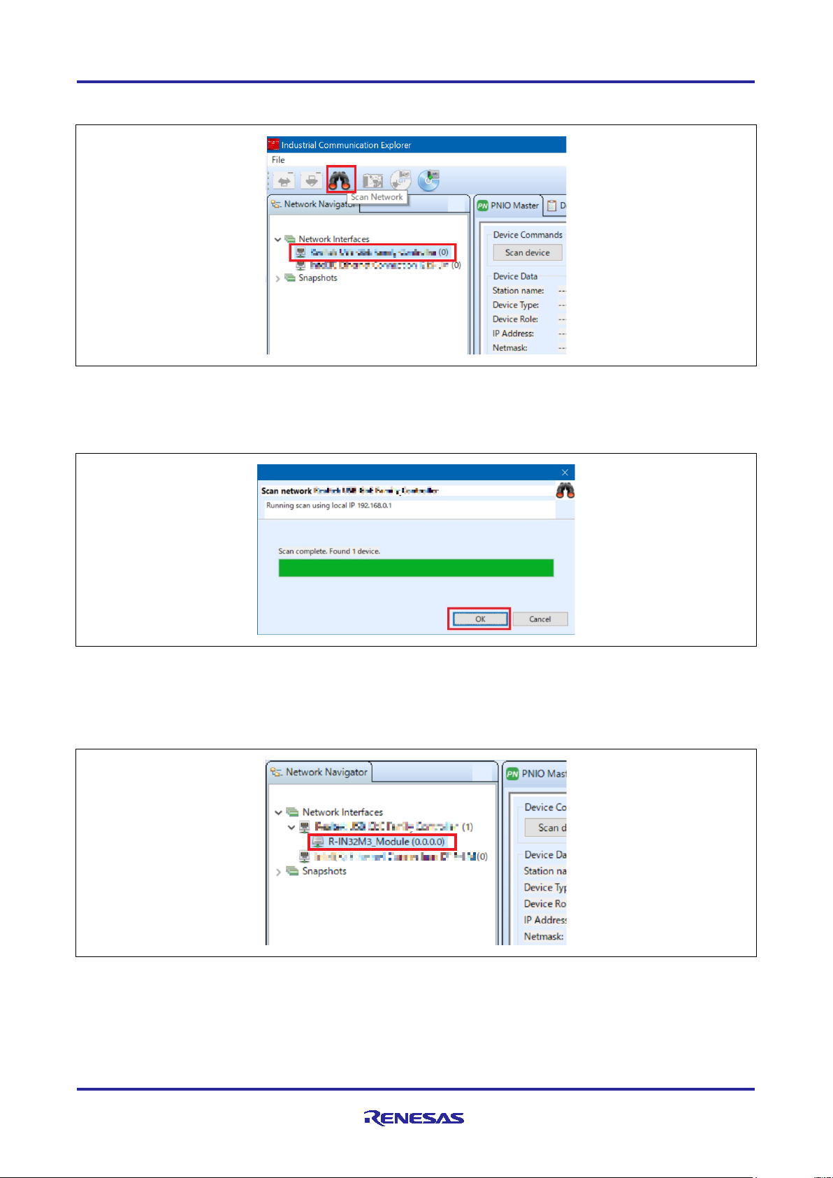
(1) Select network to use in [Network Navigator] panel and select [Scan Network] button.
Figure 3-27 Scan network
(2) “Scan complete. found 1 device” message is displayed in [Network Scan] dialog, then select [OK].
Figure 3-28 Scan completed
(3) In [Network Navigator] panel in the scanned network, R-IN32M3 Module is displayed as the new device,
so select [R-IN32M3 Module].
Figure 3-29 Select R-IN32M3 Module
R12AN0111EJ0204 Rev.2.04 Page 44 of 88
Apr.26.2021
Page 45

R-IN32M3 Module (RY9012A0) R-IN32M3 Module Evaluation Board
(4) In order to communicate with the R-IN32M3 Module, the IP address of the R-IN32M3 Module must be in
the same IP network as the IP address of the PC. Therefore, access the configuration manager variables
(volatile memory and non-volatile memory stored configuration variables) of the R-IN32M3 Module to set the
IP address, Netmask, and Gateway.
With [R-IN32M3 Module] selected, select [Read Configuration] button while displaying the [ConfigManager]
panel.
Figure 3-30 ConfigManager
(5) In the configurations displayed in the [ConfigManager] panel, change the following items: The changed
Value will be highlighted in yellow.
- Module = GOAL_ID_NET、Variable = IP, Value = IP address (Here, for example 192.168.0.100)
- Module = GOAL_ID_NET、Variable = NETMASK, Value = Netmask (Here, for example 255.255.255.0)
- Module = GOAL_ID_NET、Variable = VALID, Value = 0x01
Figure 3-31 Set IP address
R12AN0111EJ0204 Rev.2.04 Page 45 of 88
Apr.26.2021
Page 46

R-IN32M3 Module (RY9012A0) R-IN32M3 Module Evaluation Board
(6) Select [Write Configuration] button to download the changed Configuration Manager variables to the RIN32M3 Module.
Figure 3-32 Download Config variables
(7) If a change confirmation dialog is displayed, select [Yes]. The changed value is then transferred to the RIN32M3 Module and changed in RAM only. If change the value of Flash incorporated in the R-IN32M3
Module, use the [Save config to flash]. The changed IP address setting is applied after the system is
restarted, so restart this board.
(8) Select [PNIO Master] panel, and then select [Scan device].
Figure 3-33 PNIO Master
R12AN0111EJ0204 Rev.2.04 Page 46 of 88
Apr.26.2021
Page 47

R-IN32M3 Module (RY9012A0) R-IN32M3 Module Evaluation Board
(9) When a PROFINET device is detected, "PNIO: Found 1 device" appears in [Messages] panel at the
bottom of the screen, and [Device Data] in the [PNIO Master] panel displays the Device Type = Renes
Electronics, IP Address = 192.168.0.10, Netmask = 255.255.255.0, displays device information of the RIN32M3 Module.
Figure 3-34 Device Data display
(10) Open the I/O panel of [PNIO Master] panel and select [Load GSDML file] button to import the GSDML
file. GSDML files can be found in the following folder:
\appl\mirror_io_sample\01_pnio\gsdml
Verify that [Slots:] and [Modules] display contents as set in GSDML, and then select [Connect] button. If the
connection is successful, this button switches to [Disconnect] button. In addition, the protocol status LED
(LED4) on this board lights up.
Figure 3-35 GSDML
R12AN0111EJ0204 Rev.2.04 Page 47 of 88
Apr.26.2021
Page 48

R-IN32M3 Module (RY9012A0) R-IN32M3 Module Evaluation Board
Sample Application
\appl\mirror_io_sample\02_eip
Project File
\projects\mirror_io_sample\02_eip\e2studio\RX66T\FreeRTOS
(11) After the connection is complete, move the slider bar down in [PNIO Master] panel to display [I/O Data],
which monitors cyclic communication. The I/O mirror response is verified by operating 1 byte and 2byte data
of [Output Data].
<example>
- Type "0x11" in [Output Data] of [O Signed8], then "0x11" in [Input Data] of [I Signed8] is displayed
- Type "0x2233" in [Output Data] of [O Signed16], then “0x2233" in [Input Data] of [I Signed16] is displayed
Figure 3-36 Confirmation of I/O mirror
3.3.2 I/O mirror response (via EtherNet/IP)
This chapter describes an example of I/O mirror response via EtherNet/IP communication by running the
following sample project (FreeRTOS version):
Project file name on e2studio:
mirror_io_sample__02_eip__RX66T_FreeRTOS
Preparation of development environment is the same as Chapter 3.3.1.
When the sample application is run, a totally 5 LEDs light up. (protocol display LED (LED2) and generalpurpose output LED (LED5, 6, 8, 9)). Also, protocol status LED4 is light up and LED7 flashes.
Network adapter setting is the same as Chapter 3.3.1.
Management tool can be used as a EtherNet/IP master, which is also the same as Chapter 3.3.1.
By referring to the following operation of Management tool, confirm EtherNet/IP connection to this sample
application and verify the I/O mirror response by cyclic communication.
R12AN0111EJ0204 Rev.2.04 Page 48 of 88
Apr.26.2021
Page 49

R-IN32M3 Module (RY9012A0) R-IN32M3 Module Evaluation Board
(1) In [Network Navigator] panel, select the network to use, and then select the Scan Network button.
Figure 3-37 Scan network
(2) ”Scan complete. found 1 device” message is displayed in [Network Scan] dialog, then select [OK].
Figure 3-38 Scan completed
(3) In [Network Navigator] panel in the scanned network, R-IN32M3 Module is displayed as the new device,
so select [R-IN32M3 Module].
Note that in the I/O mirror response sample application via EtherNet/IP, the IP address of the R-IN32M3
Module is fixed (the default value is 192.168.0.100)). It is in the same IP network as the PC; therefore, it is
not necessary to access the configuration manager variable of the R-IN32M3 Module to set the IP address,
Netmask, or Gateway.
Figure 3-39 Select R-IN32M3 Module
R12AN0111EJ0204 Rev.2.04 Page 49 of 88
Apr.26.2021
Page 50

R-IN32M3 Module (RY9012A0) R-IN32M3 Module Evaluation Board
(4) Open [EtherNet/IP Master] panel and select [Scan device] button.
Figure 3-40 Scan device
(5) When an EtherNet/IP device is detected, [Messages panel] at the bottom of the screen displays "EIP:
Found 1 device" and [Device Data] in [EtherNet/IP Master] panel displays the device information for the RIN32M3 Module at 192.168.0.100.
Figure 3-41 Device Data display
R12AN0111EJ0204 Rev.2.04 Page 50 of 88
Apr.26.2021
Page 51

R-IN32M3 Module (RY9012A0) R-IN32M3 Module Evaluation Board
(6) Open [I/O Data] panel in [EtherNet/IP Master] panel and select [Connect] button. If the connection is
successful, this button switches to [Disconnect] button. In addition, the protocol status LED (LED7) on this
board changes from flashing to lighting up (LED4 remains lit).
Figure 3-42 I/O Data panel
(7) After the connection is complete, move the slider bar down in [EtherNet/IP Master] panel to display [I/O
Data O->T] and [I/O Data T->O], which monitor cyclic communication. The I/O mirror response is verified by
operating the 32byte data of [I/O Data O->T].
<example>
- Type "12 34 56 78 90 00 00 00 00 ... 00 00 00 09 87 65 43 21" in [I/O Data O-> T], then "12 34 56 78 90 00
00 00 ... 00 00 00 09 87 65 43 21" in [I/O Data T->O] is displayed
Figure 3-43 Confirmation of I/O mirror response
R12AN0111EJ0204 Rev.2.04 Page 51 of 88
Apr.26.2021
Page 52

R-IN32M3 Module (RY9012A0) R-IN32M3 Module Evaluation Board
Sample Application
\appl\mirror_io_sample\03_ecat
Project File
\projects\mirror_io_sample\03_ecat\e2studio\RX66T\FreeRTOS
3.3.3 I/O mirror response (via EtherCAT)
This chapter describes an example of I/O mirror response via EtherCAT communication by running the
following sample project (FreeRTOS version):
Project file name on e2studio:
mirror_io_sample__03_ecat__RX66T_FreeRTOS
To use this sample application, you need to update the firmware version of the R-IN32M3 Module to 2.0.0.0
or later. For the firmware update method, refer to “R-IN32M3 Module (RY9012A0) Quick Start Guide”
(R12QS0042ED****).
Preparation of development environment is the same as Chapter 3.3.1.
When the sample application is run, a totally 5 LEDs light up. (protocol display LED (LED3) and generalpurpose output LED (LED5, 6, 8, 9).
TwinCAT made by Beckhoff Automation can be used as a EtherCAT master. TwinCAT is available from the
Beckhoff Automation website.
http://www.beckhoff.com/
As a preparation before TwinCAT startup, you need to store the sample application’s EtherCAT Slave
information (ESI) file to TwinCAT folder on your PC.
[ESI file]
\appl\mirror_io_sample\03_ecat\esi\03_ecat_slave_renesas.xml
(Displayed name on TwinCAT: RIN32M3 Module)
[Folder to store ESI file]
C:\TwinCAT\3.1\Config\Io\EtherCAT
By referring to the following operation of TwinCAT, confirm EtherCAT connection to this sample application
and verify the I/O mirror response by cyclic communication.
(1) From the start menu on your PC, select [Beckhoff] -> [TwinCAT 3] -> [TwinCAT XAE (VS 20 xx)].
(2) After starting TwinCAT, select [File] -> [New] -> [Project] and create a new project of type [TwinCAT XAE
Project].
R12AN0111EJ0204 Rev.2.04 Page 52 of 88
Apr.26.2021
Page 53

R-IN32M3 Module (RY9012A0) R-IN32M3 Module Evaluation Board
(3) In TwinCAT project tree, right-click [I/O] -> [Devices] and select [Scan].
Figure 3-44 Scan network
(4) Click [OK] on [HINT: Not all types of devices can be found automatically] dialog.
(5) In the [new I/O devices found] dialog, select the check box of Ethernet adapter to be scanned and click
[OK].
(6) Click [Yes] in [Scan for Boxes] dialog, scanning is started and the devices in the EtherCAT segment are
recognized automatically.
(7) When [Active Free Run] dialog is displayed, click [Yes]. In TwinCAT project tree, display [Device x] ->
[Box 1] is added under [I/O] -> [Devices].
Figure 3-45 Box 1
R12AN0111EJ0204 Rev.2.04 Page 53 of 88
Apr.26.2021
Page 54

R-IN32M3 Module (RY9012A0) R-IN32M3 Module Evaluation Board
(8) If the EEPROM is blank and [Box 1 (PFFFFFFFF RFFFFFFFF)] is displayed, or if the ESI of different
sample application is written, it is necessary to write the ESI file of corresponding sample application to the
EEPROM. In TwinCAT project tree, double-click [Device x] -> [Box 1] -> [I/O] -> [Devices], the window is
displayed on the right side. Select the [EtherCAT] panel and click the [Advanced Settings].
If the ESI file of corresponding sample application has already been written to EEPROM, please go to steps
(14).
Figure 3-46 EEPROM setting
(9) Select [ESC Access] -> [EEPROM] -> [Hex Editor] in the left side of [Advanced Settings] dialog.
(10) In the [Hex Editor] window, click [Download from list].
(11) In [Write EEPROM] dialog, select [Renesas Electronics Corp] -> [RIN32M3 Module]. Select the ESI file
of corresponding sample application and click [OK]. This writes the ESI file is written to EEPROM. When the
writing is complete, click [OK] to close [Advanced Settings] dialog.
(12) In order to reflect the changed ESI file settings in TwinCAT project, disconnect the connected device
once. Right-click [I/O] -> [Devices] -> [Device x] and select [Remove].
Figure 3-47 Remove device
(13) Follow steps (3) to (7) for connection the device again.
R12AN0111EJ0204 Rev.2.04 Page 54 of 88
Apr.26.2021
Page 55

R-IN32M3 Module (RY9012A0) R-IN32M3 Module Evaluation Board
(14) Double-click [I/O] -> [Devices] -> [Device x] -> [Box 1] in TwinCAT project tree, the window is displayed
on the right side. Select [Online] panel. If connection is successful, "OP" is displayed in [Current Status] and
[Requested State]. In addition, the protocol status LED (LED4) on this board lights up.
Figure 3-48 Connection successful
(15) After the connection is complete, expand [Box 1] in TwinCAT project tree and expand [TxPDO 1] and
[RxPDO 1], which monitor cyclic communication. The I/O mirror response is verified by operating 1byte data
of [digital Inputs 1-8] and [digital Outputs 1-8].
Right-click [digital Inputs 1-8], select [Add to Watch]. Similarly, right-click [digital Outputs 1-8], and select
[Add to Watch]. This can watch IN and OUT data on one screen in the [symbol Watch] panel.
Figure 3-49 Add to Watch
R12AN0111EJ0204 Rev.2.04 Page 55 of 88
Apr.26.2021
Page 56

R-IN32M3 Module (RY9012A0) R-IN32M3 Module Evaluation Board
(16) For operating each value, Right-click [digital Outputs 1-8] or [digital Inputs 1-8], select [Online Write…]. It
is enabled to set the value on [Set Value Dialog] dialog that is displayed.
Figure 3-50 Online Write
Figure 3-51 Set Value Dialog
<example>
- Type "12" in [Dec] of [digital Outputs 1-8], then “12” in [digital Inputs 1-8] is displayed
Figure 3-52 Confirmation I/O mirror response
R12AN0111EJ0204 Rev.2.04 Page 56 of 88
Apr.26.2021
Page 57

R-IN32M3 Module (RY9012A0) R-IN32M3 Module Evaluation Board
Sample
\appl\motor_sample\01_pnio
Project File
\projects\motor_sample\01_pnio\e2studio\RX66T\OSless
3.3.4 Motor Sample (via PROFINET)
This chapter describes an example of motor control via PROFINET communication by running the following
sample project (OS less version):
Application
Project file name on e2studio:
motor_sample__01_pnio__RX66T_OSless
At first, refer to Chapter 3.2. to prepare the development environment.
(1) This sample application requires an inverter board, so connect it as shown in Figure 3-7.
(2) Build the project and run the sample application, referring to Chapters 3.2.4 to 3.2.6.
When the sample application is run, a totally 5 LEDs light up. (protocol display LED (LED1) and generalpurpose output LED (LED5, 6, 8, 9).
Network adapter setting is the same as Chapter 3.3.1.
Management tool can be used as a PROFINET master, which is also the same as Chapter 3.3.1.
By referring to the following operation of Management tool, confirm PROFINET connection to this sample
application and verify the motor control by cyclic communication. Since steps (1) to (9) are the same as
Chapter 3.3.1, only steps (10) and beyond are described below.
(10) Open the I/O panel of [PNIO Master] panel and select [Load GSDML file] button to import the GSDML
file. GSDML files can be found in the following folder:
\appl\motor_sample\01_pnio\gsdml
Verify that [Slots:] and [Modules] display contents as set in GSDML, and then select [Connect] button. If the
connection is successful, this button switches to [Disconnect] button. In addition, the protocol status LED
(LED4) on this board lights up.
Figure 3-53 GSDML
R12AN0111EJ0204 Rev.2.04 Page 57 of 88
Apr.26.2021
Page 58

R-IN32M3 Module (RY9012A0) R-IN32M3 Module Evaluation Board
Operating Data
Motor control
[O Signed8] -> [Output Data]
Select movement
[O Signed16] -> [Output Data]
Specify rotation speed (Big Endian)
(11) After the connection is complete, move the slider bar down in [PNIO Master] panel to display [I/O Data],
which monitors cyclic communication. The motor control is verified by operating 1byte and 2byte data of
[Output Data].
0x00:Stop
0x01:FWD rotation (clockwise(CW))
0x02:RVS rotation (counter-clockwise(CCW))
By typing data as follows, the motor rotates FWD (CW) at the specified rotational speed.
- [O Signed8] -> [Output Data] = ”0x01”, [O Signed16] -> [Output Data] = ”0080”
Figure 3-54 CW
Also, by typing data as follows, the motor rotates RVS (CCW) at the specified rotational speed.
- [O Signed8] -> [Output Data] = ”0x02”, [O Signed16] -> [Output Data] = ”0x0070”
Figure 3-55 CCW
R12AN0111EJ0204 Rev.2.04 Page 58 of 88
Apr.26.2021
Page 59

R-IN32M3 Module (RY9012A0) R-IN32M3 Module Evaluation Board
Sample Application
\appl\motor_sample\02_eip
Project File
\projects\motor_sample\02_eip \e2studio\RX66T\OSless
Operating Data
Motor control
1st byte in [I/O Data O->T]
Select movement
3rd and 4th byte in [I/O Data O->T]
Specify rotation speed (Big Endian)
3.3.5 Motor Sample (via EtherNet/IP)
This chapter describes an example of motor control via EtherNet/IP communication by running the following
sample project (OS less version):
Project file name on e2studio:
motor_sample__02_eip__RX66T_OSless
Preparation of development environment is the same as Chapter 3.3.4.
When the sample application is run, a totally 5 LEDs light up. (protocol display LED (LED2) and generalpurpose output LED (LED5, 6, 8, 9). Also, protocol status LED4 is light up and LED7 flashes.
Network adapter setting is the same as Chapter 3.3.1.
Management tool can be used as a EtherNet/IP master, which is also the same as Chapter 3.3.1.
By referring to the following operation of Management tool, confirm EtherNet/IP connection to this sample
application and verify the motor control by cyclic communication. Since steps (1) to (6) are the same as
Chapter 3.3.2, only step (7) and beyond are described below.
(7) After the connection is complete, move the slider bar down in the EtherNet/IP Master panel and display
[I/O Data O->T] and [I/O Data T->O], which monitor cyclic communication. The motor control is verified by
operating 32byte data of [I/O Data O->T].
0x00:Stop
0x01:FWD rotation (clockwise(CW))
0x02:RVS rotation (counter-clockwise(CCW))
R12AN0111EJ0204 Rev.2.04 Page 59 of 88
Apr.26.2021
Page 60

R-IN32M3 Module (RY9012A0) R-IN32M3 Module Evaluation Board
<example>
By typing data as follows, the motor rotates FWD (CW) at the specified rotational speed.
st
- 1
byte in [I/O Data O->T] = “01”, 3rd byte and 4
th
byte in [I/O Data O->T] = ”00 60”
Figure 3-56 CW
Also, by typing data as follows, the motor rotates RVS (CCW) at the specified rotational speed.
st
- 1
byte in [I/O Data O->T] = ”02”, 3rd and 4th byte in [I/O Data O->T] = ”00 70”
Figure 3-57 CCW
R12AN0111EJ0204 Rev.2.04 Page 60 of 88
Apr.26.2021
Page 61

R-IN32M3 Module (RY9012A0) R-IN32M3 Module Evaluation Board
Sample Application
\appl\motor_sample\03_ecat
Project File
\projects\motor_sample\03_ecat\e2studio\RX66T\OSless
3.3.6 Motor control (via EtherCAT)
This chapter describes an example of motor control via EtherCAT communication by running the following
sample project (OS less version):
Project file name on e2studio:
motor_sample__03_ecat__RX66T_OSless
To use this sample application, you need to update the firmware version of the R-IN32M3 Module to 2.0.0.0
or later. For the firmware update method, refer to “R-IN32M3 Module (RY9012A0) Quick Start Guide”
(R12QS0042ED****).
Preparation of development environment is the same as Chapter 3.3.4.
When the sample application is run, a totally 5 LEDs light up. (protocol display LED (LED3) and generalpurpose output LED (LED5, 6, 8, 9).
TwinCAT can be used as a EtherCAT master, which is also the same as Chapter 3.3.3.
As a preparation before TwinCAT startup, you need to store the sample application’s EtherCAT Slave
information (ESI) file to TwinCAT folder on your PC.
[ESI file]
\appl\motor_sample\03_ecat \esi\03_ecat_mtr_slave_renesas.xml
(Displayed name on TwinCAT: RIN32M3 Module (Motor sample))
[Folder to store ESI file]
C:\TwinCAT\3.1\Config\Io\EtherCAT
By referring to the following operation of TwinCAT, confirm EtherCAT connection to this sample application
and verify the motor control by cyclic communication. Since steps (1) to (14) are the same as Chapter 3.3.3,
only step (15) and beyond are described below.
R12AN0111EJ0204 Rev.2.04 Page 61 of 88
Apr.26.2021
Page 62

R-IN32M3 Module (RY9012A0) R-IN32M3 Module Evaluation Board
Operating Data
Motor control
[Motor start/stop switch]
Select movement
[Motor velocity]
Specify rotation speed (Big Endian)
(15) After the connection is complete, expand [Box 1] in TwinCAT project tree and expand [RxPDO 1], which
monitors cyclic communication. The motor control is verified by operating 1byte data of [Motor start/stop
switch] and 2byte data of [Motor velocity].
0x00:Stop
0x01:FWD rotation (clockwise(CW))
0x02:RVS rotation (counter-clockwise(CCW))
For operating each value, Right-click [Motor start/stop switch] or [Motor velocity], select [Online Write…]. It is
enabled to set the value on [Set Value Dialog] dialog that is displayed.
<example>
By typing data as follows, the motor rotates FWD (CW) at the specified rotational speed.
- [Dec] of [Motor start/stop switch] = ”1”, [Dec] of [Motor velocity] = ”128”
Figure 3-58 CW
Also, by typing data as follows, the motor rotates RVS (CCW) at the specified rotational speed.
- [Dec] of [Motor start/stop switch] = ”2”, [Dec] of [Motor velocity] = ”80”
Figure 3-59 CCW
R12AN0111EJ0204 Rev.2.04 Page 62 of 88
Apr.26.2021
Page 63

R-IN32M3 Module (RY9012A0) R-IN32M3 Module Evaluation Board
Sample Application
\appl\remote_io_sample\01_pnio
Project File
\projects\remote_io_sample\01_pnio\e2studio\RX66T\RI600V4
3.3.7 Remote I/O (via PROFINET)
This chapter describes an example of Remote I/O via PROFINET communication by running the following
sample project (uITRON version):
Project file name on e2studio:
remote_io_sample__01_pnio__RX66T_RI600V4
Preparation of development environment is the same as Chapter 3.3.1.
When the sample application is run, protocol display LED (LED1) light up.
Network adapter setting is the same as Chapter 3.3.1.
Management tool can be used as a PROFINET master, which is also the same as Chapter 3.3.1.
By referring to the following operation of Management tool, confirm PROFINET connection to this sample
application and verify the Remote I/O by cyclic communication. Since steps (1) to (9) are the same as
Chapter 3.3.1, only steps (10) and beyond are described below.
(10) Open the I/O panel of [PNIO Master] panel and select [Load GSDML file] button to import the GSDML
file. GSDML files can be found in the following folder:
\appl\remote_io_sample\01_pnio\gsdml
Verify that [Slots:] and [Modules] display contents as set in GSDML, and then select [Connect] button. If the
connection is successful, this button switches to [Disconnect] button. In addition, the protocol status LED
(LED4) on this board lights up.
Figure 3-60 GSDML
R12AN0111EJ0204 Rev.2.04 Page 63 of 88
Apr.26.2021
Page 64

R-IN32M3 Module (RY9012A0) R-IN32M3 Module Evaluation Board
Corresponding data
Corresponding
Remote control
[Switch]
SW2,4,5,6
By operating SW2,4,5,6 on this board, the bit value of
SW6 : bit3
[LED]
LED5,6,8,9
By operating the bit value of [LED] on Management tool,
bit3 : LED9
(11) After the connection is complete, move the slider bar down in [PNIO Master] panel to display [I/O Data],
which monitors cyclic communication. The Remote I/O is verified by operating 1byte data of [Switch] and
[LED], and operating SW and LED on this board.
on Management tool
<example>
- Set SW2,6 on this board to "H" side, then "9" in [Switch] on Management tool is displayed
function on this board
[Switch] on Management tool change (High : 1, Low : 0).
Each link is below:
SW2 : bit0
SW4 : bit1
SW5 : bit2
LED5,6,8,9 on this board change (1 : light up, 0 : turn
off).
Each link is below:
bit0 : LED5
bit1 : LED6
bit2 : LED8
Figure 3-61 Confirmation of Input
- Type “0x07” in [LED] on Management tool, general-purpose output LED (LED5,6,8) on this board is lighted
up
Figure 3-62 Confirmation of Output
R12AN0111EJ0204 Rev.2.04 Page 64 of 88
Apr.26.2021
Page 65

R-IN32M3 Module (RY9012A0) R-IN32M3 Module Evaluation Board
Sample Application
\appl\remote_io_sample\02_eip
Project File
\projects\remote_io_sample\02_eip\e2studio\RX66T\RI600V4
Corresponding data
Corresponding
Remote control
1st byte in [I/O Data
LED5,6,8,9
By operating the bit value of 1st byte in [I/O Data O->T]
bit3 : LED9
1st byte in [I/O Data
SW2,4,5,6
By operating SW2,4,5,6 on this board, the bit value of 1st
SW6 : bit3
3.3.8 Remote I/O (via EtherNet/IP)
This chapter describes an example of Remote I/O via EtherNet/IP communication by running the following
sample project (uITRON version):
Project file name on e2studio:
remote_io_sample__02_eip__RX66T_RI600V4
Preparation of development environment is the same as Chapter 3.3.1.
When the sample application is run, protocol display LED (LED2) light up. Also, protocol status LED4 is light
up and LED7 flashes.
Network adapter setting is the same as Chapter 3.3.1.
Management tool can be used as a EtherNet/IP master, which is also the same as Chapter 3.3.1.
By referring to the following operation of Management tool, confirm EtherNet/IP connection to this sample
application and verify the Remote I/O by cyclic communication. Since steps (1) to (6) are the same as
Chapter 3.3.2, only steps (7) and beyond are described below.
(7) After the connection is complete, move the slider bar down in [EtherNet/IP Master] panel to display [I/O
Data O->T] and [I/O Data T->O], which monitor cyclic communication. The Remote I/O is verified by
operating 32byte data of [I/O Data O->T] and [I/O Data T->O], and operating SW and LED on this board.
on Management tool
O->T]
T->O]
function on this board
on Management tool, LED5,6,8,9 on this board change
(1 : light up, 0 : turn off).
Each link is below:
bit0 : LED5
bit1 : LED6
bit2 : LED8
byte in [I/O Data T->O] on Management tool change
(High : 1, Low : 0).
Each link is below:
SW2 : bit0
SW4 : bit1
SW5 : bit2
R12AN0111EJ0204 Rev.2.04 Page 65 of 88
Apr.26.2021
Page 66

R-IN32M3 Module (RY9012A0) R-IN32M3 Module Evaluation Board
<example>
- Type “0A” in [I/O Data O->T] on Management tool, general-purpose output LED (LED6,9) on this board is
lighted up
Figure 3-63 Confirmation of Output
- Set SW4,5,6 on this board to "H" side, then "0E" in [I/O Data T->O] on Management tool is displayed
Figure 3-64 Confirmation of Input
R12AN0111EJ0204 Rev.2.04 Page 66 of 88
Apr.26.2021
Page 67

R-IN32M3 Module (RY9012A0) R-IN32M3 Module Evaluation Board
Sample Application
\appl\remote_io_sample\03_ecat
Project File
\projects\remote_io_sample\03_ecat\e2studio\RX66T\RI600V4
3.3.9 Remote I/O (via EtherCAT)
This chapter describes an example of Remote I/O via EtherCAT communication by running the following
sample project (uITRON version):
Project file name on e2studio:
remote_io_sample__03_ecat__RX66T_RI600V4
To use this sample application, you need to update the firmware version of the R-IN32M3 Module to 2.0.0.0
or later. For the firmware update method, refer to “R-IN32M3 Module (RY9012A0) Quick Start Guide”
(R12QS0042ED****).
Preparation of development environment is the same as Chapter 3.3.1.
When the sample application is run, protocol display LED (LED3) light up.
TwinCAT can be used as a EtherCAT master, which is also the same as Chapter 3.3.3.
As a preparation before TwinCAT startup, you need to store the sample application’s EtherCAT Slave
information (ESI) file to TwinCAT folder on your PC.
[ESI file]
\appl\remote_io_sample\03_ecat\esi\03_ecat_slave_rmtio_renesas.xml
(Displayed name on TwinCAT: RIN32M3 Module (Remote I/O sample))
[Folder to store ESI file]
C:\TwinCAT\3.1\Config\Io\EtherCAT
By referring to the following operation of TwinCAT confirm EtherCAT connection to this sample application
and verify the Remote I/O by cyclic communication. Since steps (1) to (14) are the same as Chapter 3.3.3,
only steps (15) and beyond are described below.
R12AN0111EJ0204 Rev.2.04 Page 67 of 88
Apr.26.2021
Page 68

R-IN32M3 Module (RY9012A0) R-IN32M3 Module Evaluation Board
Corresponding data
Corresponding
Remote control
[SW]
SW2,4,5,6
By operating SW2,4,5,6 on this board, the bit value of
SW6 : bit3
[LED]
LED5,6,8,9
By operating the bit value of [LED] on TwinCAT,
bit3 : LED9
(15) After the connection is complete, expand [Box 1] in TwinCAT project tree and expand [TxPDO 1] and
[RxPDO 1], which monitor cyclic communication. The Remote I/O is verified by operating 1byte data of [SW]
and [LED], and operating SW and LED on this board.
on TwinCAT
For confirming [SW] value, select [SW], select [Online Write…]. Since window is displayed on the right side,
it is enabled to watch current value in [Value] of this panel.
For operating [LED] value, Right-click [LED], select [Online Write…]. It is enabled to set the value on [Set
Value Dialog] dialog that is displayed.
function on this board
[SW] on TwinCAT (High : 1, Low : 0).
Each link is below:
SW2 : bit0
SW4 : bit1
SW5 : bit2
LED5,6,8,9 on this board change (1 : light up, 0 : turn
off).
Each link is below:
bit0 : LED5
bit1 : LED6
bit2 : LED8
R12AN0111EJ0204 Rev.2.04 Page 68 of 88
Apr.26.2021
Page 69

R-IN32M3 Module (RY9012A0) R-IN32M3 Module Evaluation Board
<example>
- Set SW2,5 on this board to "H" side, then "5" in [Switch] on TwinCAT is displayed
Figure 3-65 Confirmation of Input
- Type “15” in [Dec] of [LED] on TwinCAT, general-purpose output LED (LED5,6,8,9) on this board is lighted
up
Figure 3-66 Confirmation of Output
R12AN0111EJ0204 Rev.2.04 Page 69 of 88
Apr.26.2021
Page 70

R-IN32M3 Module (RY9012A0) R-IN32M3 Module Evaluation Board
Use Application
Unique Processing
appl_init()
Perform initialization steps before the GOAL core part is initialized, such
appl_setup()
Configure profile settings for each protocol stack, such as vendor ID
appl_loop()
Perform normal operations, including loop control functions.
GOAL initial phase
GOAL loop phase
appl_init()
appl_setup()
appl_loop()
user application
GOAL
3.4 Application Implement Guide
This chapter describes the steps to implement unique processing as a user application.
This sample software is equipped with GOAL middleware and is structured based on its design
philosophy. GOAL provides appl_init(), appl_setup(), and appl_loop() functions for user application-specific
processing, with appl_init() and appl_setup() executed in the initial phase of goal, followed by periodic
appl_loop() in the subsequent loop phases.
Figure 3-67
The following is an overview of the unique processing of functions in the user application. These are also
defined in goal_appl.c, which is the main source code of each sample.
Table 3-3 User applications and unique processing
as initialization of each protocol stack, initialization of board-dependent
hardware.
settings. It also registers callback functions and receives data from the RIN32M3 Module through each protocol.
Overall flow of the program
R12AN0111EJ0204 Rev.2.04 Page 70 of 88
Apr.26.2021
Page 71

R-IN32M3 Module (RY9012A0) R-IN32M3 Module Evaluation Board
3.4.1 PROFINET
This chapter describes the implementation of the user application part in the motor control sample
application by PROFINET. For more information about each API, see "R-IN32M3 Module (RY9012A0) User's
Manual Software" (R17US0002ED****).
(1) appl_init
This function includes application-specific initialization steps before the GOAL core module, etc. is initialized.
To enable PROFINET in GOAL, it is necessary to call goal_pnioInit first and register the GOAL's PROFINET
stack with GOAL, therefore call the initialization routine for each module, including goal_pnioInit. The sample
program also registers board-dependent hardware initialization routines.
GOAL_STATUS_T appl_init(
void
)
{
GOAL_STATUS_T res = GOAL_OK; /* result */
/* initialize DD */
res = goal_ddInit();
if (GOAL_RES_ERR(res)) {
goal_logErr("Initialization of DD failed");
}
res = goal_snmpInit();
if (GOAL_RES_ERR(res)) {
goal_logErr("Initialization of SNMP failed");
}
/* initialize PROFINET */
res = goal_pnioInit();
if (GOAL_RES_ERR(res)) {
goal_logErr("Initialization of PROFINET failed");
}
/* initialize ccm RPC interface */
res = appl_ccmRpcInit();
if (GOAL_RES_ERR(res)) {
goal_logErr("Initialization of ccm RPC failed");
}
/* register local setup stage */
res = goal_mainStageReg(GOAL_STAGE_MODULES, &stageApplSetup, GOAL_STAGE_INIT, appl_setupLocal);
if (GOAL_RES_ERR(res)) {
goal_logErr("failed to register local appl setup stage");
}
/* initialize HTTP module */
res = goal_httpInit();
if (GOAL_RES_ERR(res)) {
goal_logErr("Initialization of http module failed");
return res;
}
return res;
}
① Initialize each module of GOAL. goal_pnioInit must be called from appl_init
①
②
①
② Registers a callback function (appl_setupLocal) to be called with the specified stage ID.
appl_setupLocal performs board-specific initialization, such as LED initialization and motor controlrelated initialization.
R12AN0111EJ0204 Rev.2.04 Page 71 of 88
Apr.26.2021
Page 72

R-IN32M3 Module (RY9012A0) R-IN32M3 Module Evaluation Board
③
(2) appl_setup
This function defines static settings for protocols, such as creating instance of PROFINET.
An instance of PROFINET is created in goal_pnioNew and ready for use. Some settings, such as how much
slot memory is reserved and which vendor ID to use, must be defined between goal_pnioInit and
goal_pnioNew. These settings are set by the API group starting with goal_pnioCfg. After goal_pnioNew, all
other APIs, such as creating slots and modules can be used.
GOAL_STATUS_T appl_setup(
void
)
{
・・・
/* initialize timeout timestamp */
tsTout = goal_timerTsGet();
res = appl_ccmLogEnable();
if (GOAL_RES_ERR(res)) {
goal_logErr("failed to enable LOG to CC");
return res;
}
res = goal_snmpNew(&pInstanceSnmp, APPL_SNMP_ID);
if (GOAL_RES_ERR(res)) {
goal_logErr("failed to create SNMP instance");
return res;
}
/* set SNMP instance id for new PNIO instance */
res = goal_pnioCfgSnmpIdSet(APPL_SNMP_ID);
if (GOAL_RES_ERR(res)) {
goal_logErr("failed to set SNMP instance id");
return res;
}
・・・
/* set identification of the slave (vendor name) */
res = goal_pnioCfgVendorNameSet(APPL_PNIO_VENDOR_NAME);
if (GOAL_RES_ERR(res)) {
goal_logErr("failed to set vendor name");
return res;
}
/* create new PROFINET instance */
res = goal_pnioNew(&pPnio, APPL_PNIO_ID, appl_pnioCb);
if (GOAL_RES_ERR(res)) {
goal_logErr("failed to create a new PROFINET instance");
return res;
}
①
②
① Create an instance of SNMP.
② Define static settings in the protocol. In this sample, the vendor ID, device ID and else are set.
③ Create an instance of PRFINET and register the main callback (appl_pnioCb) The main callback
function describes what to do depending on the state reported by the protocol stack. For information
about the reported status, see "R-IN32M3 Module (RY9012A0) User's Manual Software"
(R17US0002ED****).
R12AN0111EJ0204 Rev.2.04 Page 72 of 88
Apr.26.2021
Page 73

R-IN32M3 Module (RY9012A0) R-IN32M3 Module Evaluation Board
⑤
goal_logInfo("Initializing device structure");
/* create subslots */
res = goal_pnioSubslotNew(pPnio, APPL_API, APPL_SLOT_1, APPL_SLOT_1_SUB_1, GOAL_PNIO_FLG_AUTO_GEN);
if (GOAL_RES_ERR(res)) {
goal_logErr("failed to add subslot");
return res;
}
・・・
/* create submodules */
res = goal_pnioSubmodNew(pPnio, APPL_MOD_1, APPL_MOD_1_SUB_1, GOAL_PNIO_MOD_TYPE_INPUT,
APPL_SIZE_1_SUB_1_IN, 0, GOAL_PNIO_FLG_AUTO_GEN);
if (GOAL_RES_ERR(res)) {
goal_logErr("failed to add submodule");
return res;
}
・・・
/* plug modules into slots */
res = goal_pnioSubmodPlug(pPnio, APPL_API, APPL_SLOT_1, APPL_SLOT_1_SUB_1,
APPL_MOD_1, APPL_MOD_1_SUB_1);
if (GOAL_RES_ERR(res)) {
goal_logErr("failed to plug submodule");
return res;
}
・・・
/* PROFINET configuration succesful */
goal_logInfo("PROFINET ready");
goal_logInfo("Configuring DD");
/* start DD instance */
if (GOAL_RES_OK(res)) {
res = goal_ddNew(&pHdlDd, GOAL_DD_FEAT_ALL);
}
・・・
④
⑥
④ Create an instance of a sub-slot.
⑤ Create an instance of the sub-module and associate it with the sub-slot.
⑥ Create an instance of DD (Device Detection) and configure the static definitions. In this sample, the
customer ID and module name are set.
R12AN0111EJ0204 Rev.2.04 Page 73 of 88
Apr.26.2021
Page 74

R-IN32M3 Module (RY9012A0) R-IN32M3 Module Evaluation Board
⑧ ⑦ ⑩
/* RX DATA */
goal_logInfo("mapping of ctc rx data (CC -> AC)");
/* PROFINET: add CS of Slot 1 Subslot 1 to cyclic RX data */
if (GOAL_RES_OK(res)) {
goal_logInfo("CC: input IOCS -> AC");
mMapIoxs[APPL_IOXS_RX_SL1_SU1_CS].strDesc = APPL_IOXS_RX_SL1_SU1_CS_DESC;
res = goal_pnioDmSubslotIoxsAdd(
pPnio, /* PROFINET instance */
・・・
APPL_SLOT_1, /* slot */
APPL_SLOT_1_SUB_1 /* subslot */
);
goal_logInfo("RX: Slot 1 Subslot 1 CS: %"FMT_u32"",
goal_miDmPartIdxGet(mMapIoxs[APPL_IOXS_RX_SL1_SU1_CS].pPart));
}
・・・
/* TX DATA */
goal_logInfo("mapping of ctc tx data (AC -> CC)");
/* PROFINET: add PS of Slot 1 Subslot 1 to cyclic TX data */
if (GOAL_RES_OK(res)) {
goal_logInfo("AC: input IOPS -> CC");
res = goal_pnioDmSubslotIoxsAdd(
pPnio, /* PROFINET instance */
・・・
APPL_SLOT_1, /* slot */
APPL_SLOT_1_SUB_1 /* subslot */
);
goal_logInfo("TX: Slot 1 Subslot 1 PS: %"FMT_u32"",
goal_miDmPartIdxGet(mMapIoxs[APPL_IOXS_TX_SL1_SU1_PS].pPart));
}
・・・
/* register read callback for cyclic data, use rx mapping to get group id */
if (GOAL_RES_OK(res)) {
res = goal_miDmCbReg(NULL, pPartRxSl2Su1Data->pGroup, GOAL_MI_DM_CB_READ, appl_dmCbCyclicRx, NULL);
}
/* setup web server */
if (GOAL_RES_OK(res)) {
res = appl_httpSetup();
}
・・・
return res;
}
⑨
⑦ Map the receive data of the sub-slot to the specified DM (Data Mapper) instance.
⑧ Map the transmission data of the sub-slot to the specified DM (Data Mapper) instance.
⑨ Register a callback function (appl_dmCbCyclicRx) which performs update of cyclic data. The callback
function copies data from the receive slot to the transmission slot and removes the motor control data
(motor rotation direction and rotational speed).
⑩ Setting Web server (HTTP)
R12AN0111EJ0204 Rev.2.04 Page 74 of 88
Apr.26.2021
Page 75

R-IN32M3 Module (RY9012A0) R-IN32M3 Module Evaluation Board
(3) appl_loop
Process the data after initialization of GOAL.
void appl_loop(
void
)
{
GOAL_TIMESTAMP_T tsCur; /* current timestamp */
unsigned int cnt; /* counter */
/* Processing Motor control */
mces_motorControl();
/* get current timestamp */
tsCur = goal_timerTsGet();
/* mirror output data from submod 0:2:1 to input data from submod 0:1:1 */
if ((tsTout <= tsCur)) {
if (genericDp.leds & GOAL_MCTC_DP_LED_RED_1) {
goal_maLedSet(pMaLed, GOAL_MA_LED_LED1_RED, GOAL_MA_LED_STATE_ON);
}
else {
goal_maLedSet(pMaLed, GOAL_MA_LED_LED1_RED, GOAL_MA_LED_STATE_OFF);
}
・・・
if (genericDp.leds & GOAL_MCTC_DP_LED_GREEN_2) {
goal_maLedSet(pMaLed, GOAL_MA_LED_LED2_GREEN, GOAL_MA_LED_STATE_ON);
}
else {
goal_maLedSet(pMaLed, GOAL_MA_LED_LED2_GREEN, GOAL_MA_LED_STATE_OFF);
}
/* update timeout value */
tsTout = goal_timerTsGet() + APPL_TIMEOUT_TRIGGER_VAL;
}
/* show changes in IOXS states */
for (cnt = 0; cnt < APPL_IOXS_CNT_ELEM; cnt += 2) {
if (GOAL_TRUE == mMapIoxs[cnt].flgChg) {
mMapIoxs[cnt].flgChg = GOAL_FALSE;
goal_logInfo("IOXS changed: '%s' = 0x%x", mMapIoxs[cnt].strDesc, mMapIoxs[cnt].valPrev);
}
}
}
①
②
③
① Update the motor control according to the instructions of the host side.
② The LED lights/turns off at regular intervals, depending on the reception state of the data,
③ Clear the update state of the cyclic data.
R12AN0111EJ0204 Rev.2.04 Page 75 of 88
Apr.26.2021
Page 76

R-IN32M3 Module (RY9012A0) R-IN32M3 Module Evaluation Board
3.4.2 EtherNet/IP
This chapter describes the implementation of the user application part in the motor control sample
application by EtherNet/IP. For more information about each API, see "R-IN32M3 Module (RY9012A0)
User's Manual Software" (R17US0002ED****).
(1) appl_init
This function includes application-specific initialization steps before the GOAL core module, etc. is initialized.
To enable EtherNet/IP in GOAL, it is necessary to call goal_eipInit and register the EtherNet/IP stack with
GOAL. Therefore, call the initialization routine for each module, including goal_eipInit. The sample program
also registers board-dependent hardware initialization routines.
GOAL_STATUS_T appl_init(
void
)
{
GOAL_STATUS_T res; /* result */
/* initialize DD */
res = goal_ddInit();
if (GOAL_RES_ERR(res)) {
goal_logErr("Initialization of DD failed");
}
/* initialize ccm RPC interface */
res = appl_ccmRpcInit();
if (GOAL_RES_ERR(res)) {
goal_logErr("Initialization of ccm RPC failed");
}
res = goal_eipInit();
if (GOAL_RES_ERR(res)) {
goal_logErr("Initialization of Ethernet/IP failed");
}
/* register local setup stage */
res = goal_mainStageReg(GOAL_STAGE_MODULES, &stageApplSetup, GOAL_STAGE_INIT, appl_setupLocal);
if (GOAL_RES_ERR(res)) {
goal_logErr("failed to register local appl setup stage");
}
/* initialize HTTP module */
res = goal_httpInit();
if (GOAL_RES_ERR(res)) {
goal_logErr("Initialization of http module failed");
return res;
}
return res;
}
①
②
①
① Initialize each module of GOAL. goal_eipInit must be called from appl_init.
② Registers a callback function (appl_setupLocal) to be called with the specified stage ID.
R12AN0111EJ0204 Rev.2.04 Page 76 of 88
Apr.26.2021
Page 77

R-IN32M3 Module (RY9012A0) R-IN32M3 Module Evaluation Board
④
(2) appl_setup
This function defines static settings for protocols, such as creating instance of EtherNet/IP.
Instance of EtherNet/IP is created in goal_eipNew and available for use.
Some settings like vendor ID are necessary to be set between goal_eipInit and goal_eipNew. These settings
are set by the API group starting with goal_eipCfg. After goal_eipNew, various types of data. are accessible.
GOAL_STATUS_T appl_setup(
void
)
{
GOAL_STATUS_T res; /* result */
GOAL_MI_MCTC_INST_T *pMiMctcInst = NULL; /* MI MCTC instance */
char strVersion[APPL_VERSION_LEN]; /* version string */
GOAL_ETH_MAC_ADDR_T mac; /* mac address */
uint16_t devType = 0; /* device type */
GOAL_DD_T *pHdlDd = NULL; /* dd handle */
res = appl_ccmLogEnable();
if (GOAL_RES_ERR(res)) {
goal_logErr("failed to enable LOG to CC");
return res;
}
/* for a real device the serial number should be unique per device */
res = goal_eipCfgSerialNumSet(123456789);
if (GOAL_RES_ERR(res)) {
goal_logErr("failed to set Serial Number");
return res;
}
・・・
goal_logInfo("create new EIP instance");
res = goal_eipNew(&pHdlEip, EIP_INSTANCE_DEFAULT, main_eipCallback);
if (GOAL_RES_ERR(res)) {
goal_logErr("failed to create a new EtherNet/IP instance");
return res;
}
if (GOAL_RES_OK(res)) {
res = goal_miMctcOpen(&pMiMctcInst, GOAL_ID_DEFAULT);
}
/* add generic dp to cyclic RX data */
res = goal_eipDmDpAdd(pHdlEip, GOAL_MI_MCTC_DIR_PEER_FROM, &mpPartRxDp);
if (GOAL_RES_ERR(res)) {
goal_logErr("failed to add generic data provider");
return res;
}
①
②
③
① Defines static settings in the protocol. In this sample, the vendor ID, product code, etc. are set.
② Create an instance of EtherNet/IP. Registering the main callback (main_eipCallback). The callback
function copies data from the received data to the transmission data and removes the motor control data
(motor rotation direction and rotational speed).
③ Open an instance of the Micro Core (MCTC) module.
④ Register the allocation of received data on the data buffer.
R12AN0111EJ0204 Rev.2.04 Page 77 of 88
Apr.26.2021
Page 78

R-IN32M3 Module (RY9012A0) R-IN32M3 Module Evaluation Board
res = main_eipApplInit(pHdlEip);
if (GOAL_RES_ERR(res)) {
goal_logErr("failed to initialize assembly and attribute configuration");
return res;
}
if (GOAL_RES_OK(res)) {
res = appl_httpSetup();
}
goal_logInfo("Configuring DD");
/* start DD instance */
if (GOAL_RES_OK(res)) {
res = goal_ddNew(&pHdlDd, GOAL_DD_FEAT_ALL);
}
/* configure DD properties */
res = goal_ddCustomerIdSet(pHdlDd, APPL_DD_CUSTOMER_ID);
if (GOAL_RES_ERR(res)) {
goal_logErr("failed to configure DD customer id");
}
res = goal_ddModuleNameSet(pHdlDd, (uint8_t *) APPL_DD_MODULE_NAME);
if (GOAL_RES_ERR(res)) {
goal_logErr("failed to configure DD module name");
}
res = goal_ddFeaturesSet(pHdlDd, APPL_DD_FEATURES);
if (GOAL_RES_ERR(res)) {
goal_logErr("failed to configure DD features");
}
if (GOAL_RES_OK(res)) {
goal_logInfo("DD ready");
}
else {
goal_logErr("DD initialization failed");
}
if (GOAL_RES_OK(res)) {
res = appl_ccmInfo(strVersion, APPL_VERSION_LEN, &mac, &devType);
}
goal_logInfo("CCM version : %s", strVersion);
goal_logInfo("CCM device : %u", devType);
goal_logInfo("CCM Serial : %02x:%02x:%02x:%02x:%02x:%02x",
mac[0], mac[1], mac[2], mac[3], mac[4], mac[5]);
return res;
}
⑤
⑥
⑦
⑤ Set the created instance of EtherNet/IP to a CIP object.
⑥ Set Web server (HTTP)
⑦ Creating Instantance and setting up static definitions for the Device Detection (DD) module. In this
sample, customer ID and module name are set.
R12AN0111EJ0204 Rev.2.04 Page 78 of 88
Apr.26.2021
Page 79

void appl_loop(
}
②
R-IN32M3 Module (RY9012A0) R-IN32M3 Module Evaluation Board
(3) appl_loop
Process the data after initialization of GOAL.
void
)
{
GOAL_TIMESTAMP_T tsCur; /* current timestamp */
GOAL_STATUS_T res; /* result */
/* Processing Motor control */
mces_motorControl();
/* get current timestamp */
tsCur = goal_timerTsGet();
if ((tsTout <= tsCur)) {
/* retrieve data provider state */
res = goal_miDmSingleRead(mpPartRxDp, (uint8_t *) &genericDp);
if (GOAL_RES_ERR(res)) {
return;
}
if (genericDp.leds & GOAL_MCTC_DP_LED_RED_1) {
goal_maLedSet(pMaLed, GOAL_MA_LED_LED1_RED, GOAL_MA_LED_STATE_ON);
}
else {
goal_maLedSet(pMaLed, GOAL_MA_LED_LED1_RED, GOAL_MA_LED_STATE_OFF);
}
・・・
if (genericDp.leds & GOAL_MCTC_DP_LED_GREEN_2) {
goal_maLedSet(pMaLed, GOAL_MA_LED_LED2_GREEN, GOAL_MA_LED_STATE_ON);
}
else {
goal_maLedSet(pMaLed, GOAL_MA_LED_LED2_GREEN, GOAL_MA_LED_STATE_OFF);
}
/* update timeout value */
tsTout = goal_timerTsGet() + APPL_TIMEOUT_TRIGGER_VAL;
}
①
① The motor control is updated according to the instructions of the host.
② The LED lights/turns off at regular intervals depending on the reception state of the data.
R12AN0111EJ0204 Rev.2.04 Page 79 of 88
Apr.26.2021
Page 80

R-IN32M3 Module (RY9012A0) R-IN32M3 Module Evaluation Board
②
3.4.3 EtherCAT
This chapter describes the implementation of the user application part in the motor control sample
application by EtherCAT. For more information about each API, see "R-IN32M3 Module (RY9012A0) User's
Manual Software" (R17US0002ED****).
(1) appl_init
This function includes application-specific initialization steps before the GOAL core module, etc. is initialized.
To enable EtherCAT in GOAL, it is necessary to call goal_ecatInit first and register the EtherCAT stack with
GOAL. Therefore, call the initialization routine for each module, including goal_ecatInit. The sample program
also registers board-dependent hardware initialization routines.
GOAL_STATUS_T appl_init(
void
)
{
GOAL_STATUS_T res; /* result */
/* initialize ccm RPC interface */
res = appl_ccmRpcInit();
if (GOAL_RES_ERR(res)) {
goal_logErr("Initialization of ccm RPC failed");
}
/* initialize DD */
res = goal_ddInit();
if (GOAL_RES_ERR(res)) {
goal_logErr("Initialization of DD failed");
}
/* initialize EtherCAT */
res = goal_ecatInit();
if (GOAL_RES_ERR(res)) {
goal_logErr("Initialization of EtherCAT failed");
}
/* initialize HTTP */
res = goal_httpInit();
if (GOAL_RES_ERR(res)) {
goal_logErr("Initialization of HTTP failed");
}
/* register setup stage handler which contains steps not covered by CSAP */
if (GOAL_RES_OK(res)) {
res = goal_mainStageReg(GOAL_STAGE_MODULES, &stageApplSetup, GOAL_STAGE_INIT, appl_setupLocal);
}
return res;
}
①
① Initialize each module of GOAL. goal_ecatInit must be called from appl_init
② Register a callback function (appl_setupLocal) called with the specified stage ID.
R12AN0111EJ0204 Rev.2.04 Page 80 of 88
Apr.26.2021
Page 81

R-IN32M3 Module (RY9012A0) R-IN32M3 Module Evaluation Board
(2) appl_setup
This function defines static settings for protocols, such as creating instance of EtherCAT.
An instance of EtherCAT is created in goal_ecatNew and ready for use. Also, if necessary, configure
EtherCAT protocol before creating instance set by the API group starting with goal_ecatCfg. After creating
instance, generate the required object dictionary and set the initial values.
GOAL_STATUS_T appl_setup(
void
)
{
GOAL_STATUS_T res; /* result */
char strVersion[APPL_VERSION_LEN]; /* version string */
uint16_t devType = 0; /* device type */
GOAL_ETH_MAC_ADDR_T mac; /* mac address */
uint8_t fwSignature[16]; /* firmware signature */
uint32_t valObj = 0; /* object dictionary value */
/* enable logging from AC to CC */
res = appl_ccmLogToAcEnable();
if (GOAL_RES_ERR(res)) {
goal_logErr("failed to enable logging from CC to AC");
}
/* enable CoE emergency */
res = goal_ecatCfgEmergencyOn(GOAL_TRUE);
if (GOAL_RES_ERR(res)) {
goal_logErr("failed to enable CoE Emergency support");
}
・・・
#if APPL_ECAT_SII_INIT == 1
goal_logInfo("initializing EtherCAT SSI data");
res = appl_ccmCfgSsiVendorId(
&__03_ecat_mtr_slave_eeprom_bin[0], /* data buffer */
__03_ecat_mtr_slave_eeprom_bin_len, /* data buffer length */
APPL_ECAT_VENDOR_ID);
if (GOAL_RES_ERR(res)) {
goal_logErr("failed to configure EEPROM ssi vendor id");
}
・・・
/* configure SII in EEPROM before creating the EtherCAT instance */
res = appl_ccmEcatSsiUpdate(
&__03_ecat_mtr_slave_eeprom_bin[0], /* data buffer */
__03_ecat_mtr_slave_eeprom_bin_len, /* data buffer length */
GOAL_FALSE); /* always overwrite ssi data */
if (GOAL_RES_ERR(res)) {
goal_logErr("failed to configure EEPROM ssi data");
}
#endif
①
②
① Setting EtherCAT protocol. goal_ecatNew must be performed before an instance can be created in the
application.
② Initialization of SII. (Disabled by default)
R12AN0111EJ0204 Rev.2.04 Page 81 of 88
Apr.26.2021
Page 82

R-IN32M3 Module (RY9012A0) R-IN32M3 Module Evaluation Board
⑤ ④ ⑥
goal_logInfo("create new instance");
res = goal_ecatNew(&pHdlEcat, GOAL_ECAT_INSTANCE_DEFAULT, appl_ecatCallback);
if (GOAL_RES_ERR(res)) {
goal_logErr("failed to create a new EtherCAT instance");
return res;
}
res = appl_ecatInit(pHdlEcat);
if (GOAL_RES_ERR(res)) {
goal_logErr("failed to initialize application resources");
return res;
}
res = appl_ecatCreateObjects(pHdlEcat);
if (GOAL_RES_ERR(res)) {
goal_logErr("failed to initialize object dictionary");
return res;
}
res = goal_ecatObjValSet(
pHdlEcat,
0x1008,
0x00,
(uint8_t *) APPL_ECAT_PRODUCT_NAME,
GOAL_STRLEN(APPL_ECAT_PRODUCT_NAME));
if (GOAL_RES_ERR(res)) {
goal_logErr("failed to set product name in object dictionary");
return res;
}
・・・
/* set settings for ccm firmware update via FoE */
res = appl_ccmFoeUpdateSettings(
"ccm.efw", /* filename beginning */
0, /* 0 -> match all characters */
0, /* password */
GOAL_TRUE); /* only update in ESM state bootstrap */
if (GOAL_RES_ERR(res)) {
goal_logErr("failed to configure FoE firmware update of CC");
return res;
}
/* register a callback function to handle update events */
if (GOAL_RES_OK(res)) {
res = appl_ccmFwUpdateCbReg(appl_fwUpdateCb);
}
③
⑦
③ Create an instance of EtherCAT and register main callback (main_ecatCallback). The callback function
describes operation depending on the state reported by the protocol stack. For information about the
reported status, see “R-IN32M3 Module (RY9012A0) User's Manual Software” (R17US0002ED****)
④ Initialize the module for setting the EtherCAT Explicit Device ID. The EtherCAT Explicit Device ID switch
(SW3) is required to set the ID. For details, please refer to Chapter 2.5.3(1).
⑤ Generates each object dictionary (OD). OD is added by goal_ecatdynOdObjAdd or else, and end OD
generation by goal_ecatdynOdFinish in the end.
⑥ Set the initial value for each OD definition.
⑦ Set up firmware update via FoE.
R12AN0111EJ0204 Rev.2.04 Page 82 of 88
Apr.26.2021
Page 83

R-IN32M3 Module (RY9012A0) R-IN32M3 Module Evaluation Board
/* register http web server after 83nitialization of EtherCAT stack */
if (GOAL_RES_OK(res)) {
res = appl_httpSetup();
}
/* initialize timeout timestamp */
tsTout = goal_timerTsGet();
/* get version and information of ccm */
if (GOAL_RES_OK(res)) {
res = appl_ccmInfo(strVersion, APPL_VERSION_LEN, &mac, &devType);
}
/* update object Manufacturer Software Version */
if (GOAL_RES_OK(res)) {
res = goal_ecatObjValSet(
pHdlEcat,
0x100a,
0x00,
(uint8_t *) strVersion,
GOAL_STRLEN(strVersion));
}
・・・
valObj = 0;
if (GOAL_RES_OK(res)) {
res = appl_ccmCfgVarSet(
34, /* module id ccm */
1, /* variable id foe password */
&valObj,
sizeof(valObj)
);
}
if (GOAL_RES_OK(res)) {
goal_logInfo(“cfg variable (dd:customer id) changed to %”FMT_x32”.”, valObj);
}
return res;
}
⑧
⑨
⑧ Set Web server (HTTP)
⑨ Exchange the data with CC (R-IN32M3 Module main unit) by using RPC. Set the acquired data for OD
definition.
R12AN0111EJ0204 Rev.2.04 Page 83 of 88
Apr.26.2021
Page 84

R-IN32M3 Module (RY9012A0) R-IN32M3 Module Evaluation Board
(3) appl_loop
Process the data after initialization of GOAL.
void appl_loop(
void
)
{
GOAL_TIMESTAMP_T tsCur; /* current timestamp */
/* Processing Motor control */
mces_motorControl();
/* get current timestamp */
tsCur = goal_timerTsGet();
/* set leds */
if ((tsTout <= tsCur) && (GOAL_TRUE != flgError)) {
}
}
① The motor control is updated according to the instructions of the host.
①
R12AN0111EJ0204 Rev.2.04 Page 84 of 88
Apr.26.2021
Page 85

R-IN32M3 Module (RY9012A0) R-IN32M3 Module Evaluation Board
API
Description
RI600V4(uITRON)
FreeRTOS
1
vsta_knl
vTaskStartScheduler
Start OS
2
Creation of static instances
xEventGroupCreate
Create event flag
3
wai_flg
xEventGroupWaitBits
Monitor event flags
4
set_flg
xEventGroupSetBits
Set event flags
5
Creation of static instances
xSemaphoreCreateRecursiveMutex
Create Mutex
6
Creation of static instances
vSemaphoreDelete
Delete Mutex
7
tloc_mtx
xSemaphoreTakeRecursive
Lock Mutex
8
unl_mtx
xSemaphoreGiveRecursive
Un-Lock Mutex
9
Creation of static instances
xSemaphoreCreateBinary
Create Semaphore
10
twai_sem
xSemaphoreTake
Acquire Semaphore
11
sig_sem
xSemaphoreGive
Return Semaphore
12
act_tsk,sta_tsk
xTaskCreate
Create/Start Tasks
13
get_tid
xTaskGetCurrentTaskHandle
Get Task in Running State
14
get_pri
uxTaskPriorityGet
Get Priority of Task
15
chg_pri
vTaskPrioritySet
Set Priority of Task
16
rem_tsk
vTaskResume
Release Suspend State
17
tslp_tsk
vTaskDelay
Task Delays
18
sus_tsk
vTaskSuspend
Transit to Suspend State
19
ter_tsk
vTaskDelete
End/Delete Task
4. Appendix
4.1 GOAL API
The host microcomputer communicates with the R-IN32M3 Module via an API function to control the RIN32M3 Module provided by GOAL. The APIs are categorized by protocol, and for more information, see “RIN32M3 Module (RY9012A0) User's Manual Software” (R17US0002ED****).
4.2 OS Service Call
Table 4-1 shows the service calls used in operating environments of uITORN and FreeRTOS projects.
Table 4-1 Comparison table with OS service call
#
only
only
only
only
irem_tsk
xTaskResumeFromISR
R12AN0111EJ0204 Rev.2.04 Page 85 of 88
Apr.26.2021
Page 86

R-IN32M3 Module (RY9012A0) R-IN32M3 Module Evaluation Board
factor
changes
change reason
HW
Changed ADC channels for analog input
For changing the MCU pin allocation of
HW
Changed the conversion ratio of the inverter bus
The supply voltage of the RX66T has
HW
Changed the terminal corresponding to LED1 to 3
For changing the MCU pin allocation of
SW
Timer used for 500 [us] cycle interrupt for motor
To increase the number of free channels
SW
Changed to disable the variable resistance (VR1)
In order not to overlap with the operation
SW
Changed interrupt processing to a call via the FIT
To put the interrupt handler under OS
SW
Delete serial communication processing (SCI6).
Non-support of RMW tool.
SW
Add include files
To be able to build with both CC-RX/GNU
4.3 Motor Sample
The motor control sample software included in this sample software has made the following changes based
on the sample software for the CPU card, "Sensorless Vector Control for Permanent Magnet Synchronous
Motor (Implementation)" (R01AN4244EJ****).
Regarding hardware differences, please refer to Chapter 2.6.
Table 4-2 Changes of Motor control sample software
measurement.
VPN:AN208 -> AN003
VR1:AN217 -> AN107
voltage.
/ SW1 to 2 of the inverter board.
control changed from CMT to TMR
and toggle switch (SW1) of the inverter board
during protocol communication.
module (BSP).
the board.
been changed from 5.0[V] -> 3.3 [V]
according to the specifications of the RIN32M3 module.
the board.
of CMT timer which is used for hard
timers in GOAL.
on the board during various protocol
communication.
control (FreeRTOS and uITRON version).
To put the interrupt handler under FIT
module control (OS less version).
Change macros for interrupt-allow/prohibit
Add Padding to Structures
Change description method of #pragma
R12AN0111EJ0204 Rev.2.04 Page 86 of 88
Apr.26.2021
compilers
Page 87

R-IN32M3 Module (RY9012A0) R-IN32M3 Module Evaluation Board
Rev.
Date
Description
Page
Summary
1.00
Oct/16/2020
First Edition
2.00
Nov/06/2020
27,52,61,6
7,80
Add description about EtherCAT(Chapter 3.1.1, 3.3.3, 3.3.6,
3.3.9 and 3.4.3)
26
Change Folder Structure
28
Add FreeRTOS package download procedure
63
Add Remote I/O sample
2.01
Jan/15/2021
52,61,67
Add version and update method of FW
2.02
Jan/29/2021
5,43
Changed the description due to the version upgrade of
Management tool
16
Removed the statement that the switch is unused
2.03
Mar/31/2021
5
Update each version of operating environment
26, 27, 43
- Unify OS less environment of RX sample program
folder path
36
Add the procedure when the component is not activated in FIT
module generation
2.04
Apr/26/2021
5
Add Sample package DL link
86
Add trademark
13, 15
Modify Figure 2-6 and Table 2-4
-
-
-
-
respective owners.
Revision History
- Change the folder name and project name to shorten the
Trademark
ARM and Cortex are registered trademarks of ARM Limited (or its subsidiaries) in the EU and/or elsewhere. All rights reserved.
Ethernet is a registered trademark of Fuji Xerox Co., Ltd.
EtherCAT® and TwinCAT® are registered trademark and patented technology, licensed by Beckhoff Automation GmbH, Germany.
Additionally all product names and service names in this document are a trademark or a registered trademark which belongs to the
R12AN0111EJ0204 Rev.2.04 Page 87 of 88
Apr.26.2021
Page 88

R-IN32M3 Module (RY9012A0) R-IN32M3 Module Evaluation Board
General Precautions in the Handling of Microprocessing Unit and Microcontroller Unit Products
The following usage notes are applicable to all Microprocessing unit and Microcontroller unit products from Renesas. For detailed usage notes on the
products covered by this document, refer to the relevant sections of the document as w ell as any technical updates that have been issued for the products.
1. Precaution against Electrostatic Discharge (ESD)
A strong electrical field, when exposed to a CMOS device, can cause destruction of the gate oxide and ultimately degrade the device operation. Steps
must be taken to stop the generation of static electricity as much as possible, and quickly dissipate it when it occurs. Environmental control must be
adequate. When it is dry, a humidifier should be used. This is recommended to avoid usi ng insulators that can easily build up static electricity.
Semiconductor devices must be stored and transported in an anti-static container, static shielding bag or conductive material. All test and
measurement tools including work benches and floors must be grounded. The operator must also be grounded using a wrist strap. Semiconductor
devices must not be touched with bare hands. Similar precautions must be taken for printed circuit boards with mounted semiconductor devices.
2. Processing at power-on
The state of the product is undefined at the time when power is supplied. The states of internal circuits in the LSI are indeterminate and the states of
register settings and pins are undefined at the time when power is supplied. In a finished product where the reset signal is applied to the external reset
pin, the states of pins are not guaranteed from the time when power is supplied until the reset process is completed. In a similar way, the states of pins
in a product that is reset by an on-chip power-on reset function are not guaranteed from the time when power is supplied until the power reaches the
level at which resetting is specified.
3. Input of signal during power-off state
Do not input signals or an I/O pull-up power supply while the device is powered off. The current injection that results from input of such a signal or I/O
pull-up power supply may cause malfunction and the abnormal current that passes in the device at this time may cause degradation of internal
elements. Follow the guideline for input signal during power-off state as described in your product documentation.
4. Handling of unused pins
Handle unused pins in accordance with the directions given under handling of unused pins in the manual. The input pins of CMOS products are
generally in the high-impedance state. In operation with an unused pi n in the open-circuit state, extra electromagnetic noise is induced in the vicinity of
the LSI, an associated shoot-through current flows internally, and malfunctions occur due to the false recognition of the pin state as an input signal
become possible.
5. Clock signals
After applying a reset, only release the reset line after the operating clock signal becomes stable. When switching the clock signal during program
execution, wait until the target clock signal is stabilized. When the clock signal is generated with an external resonator or from an external oscillator
during a reset, ensure that the reset line is only released after full stabilization of the clock signal. Additionally, when switching to a clock signal
produced with an external resonator or by an external oscillator while program execution is in progress, wait until the target clock signal is stable.
6. Voltage application w aveform at input pin
Waveform distortion due to input noise or a reflected wave may cause malfunction. If the input of the CMOS device stays in the area between V
(Max.) and V
input level is fixed, and also in the transition period when the input level passes through the area between V
7. Prohibition of access to reserved addresses
Access to reserved addresses is prohibited. The reserved addresses are provided for possible future expansion of functions. Do not access these
addresses as the correct operation of the LSI is not guaranteed.
8. Differences between products
Before changing from one product to another, for example to a product with a different part number, confirm that the change will not lead to problems.
The characteristics of a microprocessing unit or microcontroller unit products in the same group but having a different part number might differ in terms
of internal memory capacity, layout pattern, and other factors, which can affect the ranges of electrical characteristics, such as characteristic values,
operating margins, immunity to noise, and amount of radiated noise. When changing to a product with a different part number, implement a system-
evaluation test for the given product.
(Min.) due to noise, for example, the device may malfunction. Take care to prevent chattering noise from entering the device when the
IH
(Max.) and VIH (Min.).
IL
IL
R12AN0111EJ0204 Rev.2.04 Page 88 of 88
Apr.26.2021
Page 89

Notice
Corporate Headquarters
Contact information
www.renesas.com
Trademarks
of their respective owners.
1. Descriptions of circuits, software and other related i nformation in this document are provided only to illustrate the operation of semiconductor products
and application examples. You are fully responsible for the incorporation or any other use of the circuits, software, and information i n the design of your
product or system. Renesas Electronics disclaims any and all liability for any losses and damages incurred by you or third parties arising from the use
of these circuits, software, or information.
2. Renesas Electronics hereby expressly disclaims any warranties against and liability for infringement or any other claims involving patents, copyrights,
or other intellectual property rights of third parties, by or arising from the use of Renesas Electronics products or technical information described in this
document, including but not limited to, the product data, drawings, charts, programs, algorithms, and application examples.
3. No license, express, implied or otherwise, is granted hereby under any patents, copyrights or other intellectual property rights of Renesas Electronics
or others.
4. You shall not alter, modify, copy, or reverse engineer any Renesas Electronics product, whether in whole or in part. Renesas Electronics disclaims any
and all liability for any losses or damages incurred by you or third parties arising from such alteration, modification, copying or reverse engineering.
5. Renesas Electronics products are classified according to the following two quality grades: “Standard” and “High Quality”. The intended applications for
each Renesas Electronics product depends on the product’s quality grade, as indicated below.
"Standard": Computers; office equipment; communications equipment; test and measurement equipment; audio and visual equipment; home
"High Quality": Transportation equipment (automobiles, trains, ships, etc.); traffic control (traffic lights); large-scale communication equipment; key
Unless expressly designated as a high reliability product or a product for harsh environments in a Renesas Electronics data sheet or other Renesas
Electronics document, Renesas Electronics products are not intended or authorized for use in products or systems that may pose a direct threat to
human life or bodily injury (artificial life support devices or systems; surgical implantations; etc.), or may cause serious property damage (space
system; undersea repeaters; nuclear power control systems; aircraft control systems; key plant systems; military equipment; etc.). Renesas Electronics
disclaims any and all liability for any damages or losses incurred by you or any third parties arising from the use of any Renesas Electronics product
that is inconsistent with any Renesas Electronics data sheet, user’s manual or other Renesas Electronics document.
6. When using Renesas Electronics products, refer to the l atest product information (data sheets, user’s manuals, application notes, “General Notes for
Handling and Using Semiconductor Devices” in the reliability handbook, etc.), and ensure that usage conditions are within the ranges specified by
Renesas Electronics with respect to maximum ratings, operating power supply voltage range, heat dissipation characteristics, installation, etc. Renesas
Electronics disclaims any and all liability for any malfunctions, failure or accident arising out of the use of Renesas Electronics products outside of such
specified ranges.
7. Although Renesas Electronics endeavors to improve the quality and reliability of Renesas Electronics products, semiconductor products have specific
characteristics, such as the occurrence of failure at a certain rate and malfunctions under certain use conditions. Unless designated as a high reliability
product or a product for harsh environments in a Renesas Electronics data sheet or other Renesas Electronics document, Renesas Electronics
products are not subject to radiation resistance design. You are responsible for implementing safety measures to guard against the possibility of bodily
injury, injury or damage caused by fire, and/or danger to the public in the event of a failure or malfunction of Renesas Electronics products, such as
safety design for hardware and software, including but not limited to redundancy, fire control and malfunction prevention, appropriate treatment for
aging degradation or any other appropriate measures. Because the evaluation of microcomputer software alone is very difficult and impractical, you are
responsible for evaluating the safety of the final products or systems manufactured by you.
8. Please contact a Renesas Electronics sales office for details as to environmental matters such as the environmental compatibility of each Renesas
Electronics product. You are responsible for carefully and sufficiently investigating applicable laws and regulations that regulate the inclusion or use of
controlled substances, including without limitation, the EU RoHS Directive, and using Renesas Electronics products in compliance with all these
applicable laws and regulations. Renesas Electronics disclaims any and all liability for damages or losses occurring as a result of your noncompliance
with applicable laws and regulations.
9. Renesas Electronics products and technologies shall not be used for or incorporated into any products or systems whose manufacture, use, or sale is
prohibited under any applicable domestic or foreign laws or regulations. You shall comply with any applicable export control laws and regulations
promulgated and administered by the governments of any countries asserting jurisdi ction over the parties or transactions.
10. It is the responsibility of the buyer or distributor of Renesas Electronics products, or any other party who distributes, disposes of, or otherwise sells or
transfers the product to a third party, to notify such third party in advance of the contents and conditions set forth in this document.
11. This document shall not be reprinted, reproduced or duplicated in any form, in whole or in part, without prior written consent of Renesas Electronics.
12. Please contact a Renesas Electronics sales office if you have any questions regarding the information contained in this document or Renesas
Electronics products.
(Note1) “Renesas Electronics” as used in this document means Renesas Electronics Corporation and also includes its directly or indirectly controlled
(Note2) “Renesas Electronics product(s)” means any product developed or manufactured by or for Renesas Electronics.
subsidiaries.
electronic appliances; machine tools; personal electronic equipment; industrial robots; etc.
financial terminal systems; safety control equipment; etc.
(Rev.4.0-1 November 2017)
TOYOSU FORESIA, 3-2-24 Toyosu,
Koto-ku, Tokyo 135-0061, Japan
Renesas and the Renesas logo are trademarks of Renesas Electronics
Corporation. All trademarks and registered trademarks are the property
For further information on a product, technology, the most up-to-date
version of a document, or your nearest sales office, please visit:
www.renesas.com/contact/
.
© 2019 Renesas Electronics Corporation. All rights reserved.
 Loading...