

Page 1

STZAN0114EN0100
1
Application Note
STZAN0114EN0100
Revision 1.00
April 2019
Getting Started with Embedded Trust and the RX65x
Introduction
This application note describes the use of the Embedded Trust and C-Trust security development environments
with the Renesas RSK+RX65N-2MB Starter Kit. The Renesas RSK series includes an LCD display module and
E2 Lite debugging emulator. The RSK also offers additional peripherals to extend the features of the board and
ease the development of custom security designs.
Target Devices
This application note refers to the following secure microcontroller :
➢ Renesas Electronics R5F565NEHDFC microcontrollers
Related Documents
➢ Renesas RSK+RX65N-2MB User’s Manual (R20UT3888EG0200 Rev 2.00 Dec 2017)
➢ E1/E20/E2 Emulator, E2 Emulator Lite (R20UT0399EJ1200 Rev.12.00 Nov 2018)
➢ Embedded Trust User Guide (available from Secure Thingz & IAR Systems websites)
Page 2
STZAN0114EN0100
2
1. Kit Overview
The Renesas RSK+RX65N-2MB Starter Kit is a hardware platform for the evaluation of the Renesas RX65N
device. The Renesas RSK+RX65N-2MB Starter Kit part number is as follows:
• YRTK50565N200010BE (Renesas RSK+RX65N-2MB Kit CS+ & E2Lite-Encrypted)
The board offers a set of features that enables the user to get started with the microcontroller peripherals
immediately and to obtain an understanding of how to integrate the device in their required design.
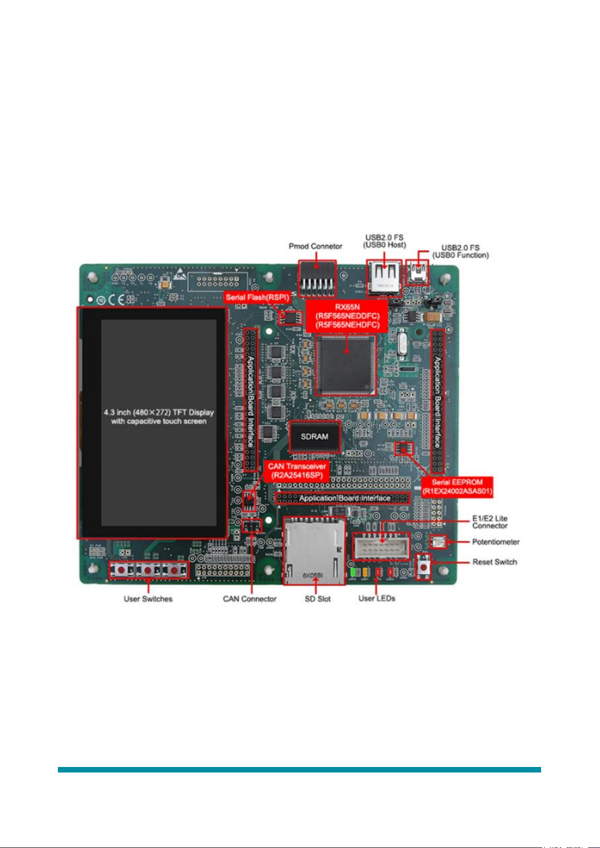
This application note is primarily concerned with the RX65N-2MB device and RSK+RX65N-2MB Kit. Figure 1
shows the features of the Renesas RSK+RX65N-2MB Starter Kit.
Figure 1: Renesas RSK+RX65N-2MB Starter Kit features
Please refer to the Renesas RSK+RX65N-2MB User’s Manual (section 7) (see Related Documents) for details of
the implementation of connectors and headers on the starter kit.
Page 3
STZAN0114EN0100
3
2. Getting Started
Download and install the following :
➢ IAR Systems Embedded Workbench for RX provided by IAR Systems
➢ Embedded Trust security development environment provided by Secure Thingz
➢ C-Trust extension to IAR Embedded Workbench provided by IAR Systems
Refer to the Installation and Licensing Quick Reference Guide available from the IAR Systems website to
determine PC system requirements.
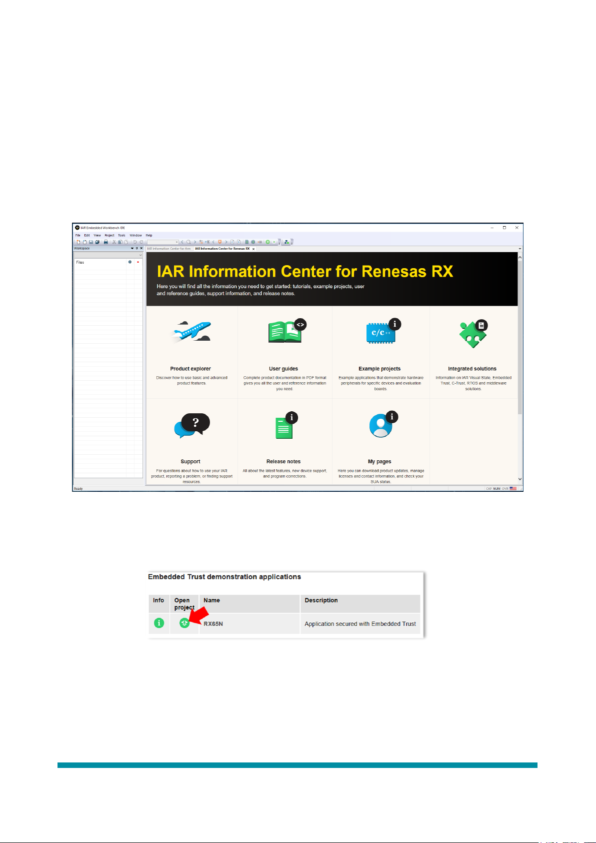
Launch Embedded Trust for RX. The tool will open as per that shown in Figure 2.
Figure 2: Embedded Trust for RX opening screen
Click on Example Projects -> Embedded Trust -> Getting Started -> RX65N Open Project (see Figure 3)
Figure 3: Open Getting Started project
An explorer dialog will open requiring the destination folder for the project to be located. Direct the open dialog
box to the folder to be used for the project and click “Select Folder”.
With the folder selected (and additional folder expansion), the IDE will look like that shown in Figure 4.
Page 4

STZAN0114EN0100
4
Figure 4: Embedded Trust with Getting Started project loaded
Click on the Project tab and select “Create New Project” in the dropdown menu. The dialog box shown in
Figure 5 will be displayed. Click on the “Tool chain” dropdown and select “RX”.
We wish to add security to the Getting Started project we have just loaded so click on Secure Boot Manager in
the “Create New Project” dialog box and click “OK”.
Figure 5: Select Secure Boot Manager in Create New Project dialog box
An explorer dialog will open requiring a filename for the Secure Boot Manager project. Enter the filename to be
used into the open dialog box and click “Save”. In this example we have used SBM as the filename.
The IDE will now load the additional Secure Boot Manager project and look like that shown in Figure 6.
Page 5
STZAN0114EN0100
5
Figure 6: IDE with Secure Boot Manager project loaded and active
Please read the Readme.txt file that is displayed in the IDE. This file includes important configuration information
for projects that are to have security added i.e. integrated with a Secure Boot Manager. Please note that "Erase
flash ROM before download" is enabled by default in the Hardware Setup dialog box (available on the debugger
driver menu in the IDE)
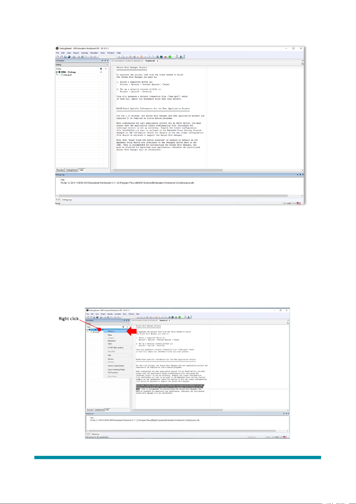
2.1 Configuring the Secure Boot Manager
The Secure Boot Manager project must now be configured for the RX65N. The configuration will be carried out
via the Project -> Options… menu provided by the IDE. To access this menu, right click on the SBM-Debug
project and select “Options…” in the dropdown menu (see Figure 7).
Figure 7: Selecting Project -> Options menu
Page 6

STZAN0114EN0100
6
The menu for Options for node “SBM” will open. Select the “General Options” category and click on the
“Target” tab. Select the Device type as “R5F565NE”.
Select the “Debugger” category and select the “E2 Lite” Driver.
Select the “Security” category and click the Enable check box. The Embedded Trust dialog box shown in Figure
8 should be the resultant display.
Figure 8: Embedded Trust dialog box
We will now create a Security Context for the Secure Boot Manager project.
Page 7

STZAN0114EN0100
7
2.2 Configuring the Security Context
In the Options for node “SBM” -> Embedded Trust dialog box (see Figure 8) click “New”. The dialog box for
“Create New Security Context” will open. Populate the values, in free text, with the required configuration. Note
that the Security Configuration information is the information that will be used to generate the Device Certificate
for the project. Figure 9 is an example of a completed Basic Setup configuration. Once the correct information
has been entered, click “Next”.
Figure 9: Basic Setup of Security Context dialog box
The Security Settings configuration dialog box will now be displayed (see Figure 10). There are two options
that require configuration, these are the Number of Certificates and the Device ID source.
Figure 10: Security Settings of Security Context dialog box
Page 8

STZAN0114EN0100
8
2.2.1 Number of certificates
This option allows the user to select the number of digital certificates that are to be implemented in the chain of
trust (Public Key Infrastructure (PKI)) for the application. Figure 11 is an example of a chain of trust with 3 levels.
A maximum of 8 levels are supported by the Secure Boot Manager, however, due to the requirement to store the
certificates in secure memory, there is a limitation on the number of certificates that can be implemented in a
usable system. The default number of levels is 3 for the RX65N when using the GettingStarted example
application.
Figure 11: Example chain of trust with 3 levels
It is recommended that the Number of certificates required option is set to the default of 3.
2.2.2 Device ID
This option concerns the serial number field in the digital certificate for the device. The serial number of the
certificate can be created from either the silicon ID of the target device or a random number generated by
Embedded Trust. If From device is selected, the silicon ID is read out of the target device during the first phase
of provisioning and used to create the certificate serial number. This certificate is then tightly bound to the target
device. Note that once completed, the certificate hash is calculated and then signed by the Certificate Authority
Private key. The Random option is an alternative to using the silicon ID. In this case, Embedded Trust will
generate a random number which will be used as the device certificate serial number.
It is recommended that From device is selected as the Device ID option as this will allow the user to check the
device certificate programmed into the device against the unique ID of the RX65N.
Once the options described and recommended in sections 2.2.1 and 2.2.2 are set click “Next”
The Secure Boot Manager Settings dialog box will now be displayed (see Figure 12). For the initial release of
Embedded Trust, there are no options within this dialog box that can be set by the user.
Page 9

STZAN0114EN0100
9
Figure 12: Secure Boot Manager Settings dialog box
Click “Create” to allow Embedded Trust to create the Security Context. A dialog box will open to confirm the use
of the profile that has just been created, click “Yes”. The dialog box shown in Figure 13 is an example of the final
Security Context created showing the newly created security context profile (in this example My Security
Context_profile-default). Click “OK”.
Figure 13: Completed Security Context example
The IDE will now return to the screen similar to that as shown in Figure 6 but with the addition of SBM source
and Output folders. Please review the Secure Boot Manager source files. These files are open source and can be
modified by the user. If the user is required to make major modifications to the Secure Boot Manager source code,
it is recommended that the changes be reviewed by Secure Thingz to ensure security is not compromised.
Page 10

STZAN0114EN0100
10
2.3 Connecting the Renesas RSK+RX65N-2MB Starter Kit
Figure 14 shows the connections that are required between the RSK+RX65N-2MB Starter Kit CPU board, E2
Lite debugger and the host PC. It is recommended that the user consult the RSK+RX65N-2MB Starter Kit Quick
Start guide for more detailed information concerning the operation of the kit. Please note that the +5V centrepositive PSU supplied with the kit is required.
Figure 14: Debugger connection diagram
In addition to the debugger connections as shown in Figure 14, an additional terminal connection is required
between the PC and the CPU board. Figure 15 shows the additional terminal output connection available on the
RSK+RX65N-2MB Starter Kit. Please connect the RSK+RX65N-2MB Starter Kit to the PC that is running the
Embedded Trust software as shown in Figures 14 and 15.
Figure 15: Connection for terminal output
Page 11

STZAN0114EN0100
11
2.3.1 E2 Lite Debugger
The RSK+RX65N-2MB Starter Kit contains the Renesas E2 Lite debugger (see Figure 16). For information about
debugging and programming features refer to E1/E20/E2 Emulator, E2 Emulator Lite User’s Manual
(r20ut0399ej1200_e1e20e2e2lite_rx.pdf), which describes in detail all the E2 Lite features.
Figure 16: Renesas E2 Lite debugger
2.4 Provisioning
Once the RSK+RX65N-2MB Starter Kit is connected to the PC that is running Embedded Trust, click on the
E2/E2 Lite tab to configure the debugger. Select “Hardware Setup” as shown in Figure 17
Figure 17: E2/E2 Lite dropdown menu
The dialog box as shown in Figure 18 will be displayed. Please check that the settings as shown in Figure 18 are
selected. Special note should be made to the “Download” category. Ensure that the “Erase Flash ROM before
download” is ticked. Once all settings have been configured, click “OK”.
Figure 18: Settings for Hardware Setup
Page 12

STZAN0114EN0100
12
With the debugger configured correctly we will now provision the RX65N on the RSK+RX65N-2MB Starter Kit.
Click on the Security tab and select “Provision” (see Figure 19).
Figure 19: Provisioning the RX65N
Embedded Trust will now build the Secure Boot Manager project. Once built, the provisioning process will begin.
During the process the device serial number will be read from the RX65N that is fitted to the RSK+RX65N-2MB
Starter Kit. The serial number will then be incorporated into the Device Certificate which will be programmed
into the secure memory of the RX65N. During provisioning the user will witness the reading of the silicon ID
with the display of an activity dialog box that will open temporarily.
Once the provisioning process is complete, it is recommended that the user review both the Debug Log and Build
console displays. In order to display all messages, please right-click within the console screens and select “All”.
Figure 20: Build messages
Figure 20 shows the build messages for the example Secure Boot Manager provisioning process. The location of
the Device, Intermediate and Root certificates generated by Embedded Trust can be seen. Please use a PEM file
reader to display the X.509 certificate information that has been created.
Now that the Secure Boot Manager has been provisioned into the RSK+RX65N-2MB Starter Kit, we can now
create a mastered image for the GettingStarted application and install into the kit.
Page 13

STZAN0114EN0100
13
2.5 Master the User Application
The focus must now be directed towards the GettingStarted application. Please click the GettingStarted tab at
the bottom of the workspace window on the left of the IDE.
Right-click on the GettingStarted filename and select “Options…” in the dropdown menu (see Figure 21)
Figure 21: GettingStarted project Options
The “Options for node “GettingStarted” dialog box will open (see Figure 22).
Select the “Security” category. This will open the Embedded Trust configuration dialog box. Click the “Enable”
radio button. We now must add the Security Context that we created in section 2.2 to the GettingStarted user
application. To do this click “Add”. An explorer window will open. Select the My Security Context_profile-default
file and click “Open”.
As we are about to master a new software image it is important to enter a version number. Enter a version number
in the format xx.xx.xx and then click “OK” (see Figure 22).
Figure 22: Adding the profile and version number
Page 14

STZAN0114EN0100
14
We are now ready to master the new software image. Click on the “Security” tab and select “Master” (see Figure
23). The GettingStarted application will be built and encrypted ready for delivery to the RSK+RX65N-2MB
Starter Kit.
Figure 23: Mastering the image
Figure 24 shows an example build log during the mastering process. Please note the name of the new encrypted
mastered image that is ready for delivery to the device.
Figure 24: Mastering process build message example
Page 15

STZAN0114EN0100
15
2.6 Updating the software
With the software built and mastered we can now download to the RSK+RX65N-2MB Starter Kit. However, we
first need to configure the E2 Lite Emulator Hardware Setup.
Click on the E2/E2 Lite tab and select “Hardware Setup” as seen in Figure 25
Figure 25: Setting up the E2 Lite for Mastering
Ensure that the “Erase flash ROM before download” in NOT selected otherwise the SBM that was previously
provisioned in section 2.4 will be erased. Figure 26 shows the correct Hardware Setup for the Mastering
programming. Once the correct settings have been selected, click “OK”.
Figure 26: Disable Flash erase before download
With the E2 Lite correctly setup ready for programming we can now simply click on the “Download and Debug”
button in the IDE. The software image will be downloaded to the RX65N into the software update memory slot.
Once this has been flashed into memory the RX65N will be reset, the Secure Boot Manager will follow its
immutable boot process, check the update slot for any new software, will see the new image, verify its version
number against the Security Context policy and, if all is well, will decrypt the software and Flash it into user
memory. The debugger will then halt at “main”. Figure 27 shows an example of the IDE after this process has
completed. Please note that there may be a delay during this process as the flashing of the encrypted image, plus
verification followed by flashing of the unencrypted image is a lengthy process.
Page 16

STZAN0114EN0100
16
Figure 27: Mastering image downloaded and booted
2.7 Running the GettingStarted application
In order to see the output of the application, open a terminal emulator and connect to the RSK+RX65N-2MB
Starter Kit COM port, it will be named RSK USB Serial Port (COMxx). (Please note that this is realised through
the USB cable connected to the Host PC - Figure 15). Terminal settings are : Baud : 115200, 8-bit, no parity, one
stop bit, no flow control. Once the terminal emulator program is up and running, click on the “Go” icon in the
Embedded Trust IDE to start the GettingStarted application. With the terminal emulator running type “H” for
help. The output should be as shown in Figure 28.
Figure 28: COM port output for GettingStarted application
Page 17

STZAN0114EN0100
17
To verify that the RX65N has been correctly provisioned, press “C”. This will display the certificate information
provisioned into the device. Figure 29 shows the output for the example entered for this application note.
Figure 29: COM port output for GettingStarted application (after “C”)
Please verify that the correct subject information has been provisioned into both root and device certificate. Note
the time for the start of the validity of the certificate, this should match the time at which the device was
provisioned.
The GettingStarted User Guide gives more detail of the function provided in the help menu.
Page 18

STZAN0114EN0100
18
Appendix A: RX65N Memory Map
The diagram shown in Figure A-1 shows the default memory map for the RX65N after provisioning of the
device has taken place (see Section 2.4).
Figure A-1: RX65N Memory Map
Memory Map details
The Flash is operated in Linear Mode, whereby it is considered to be a single 2MB region of memory.
SBM occupies Trusted Memory blocks 8, 9, and 10. It reserves another 32KB of Flash at block 69 for metadata.
The application firmware occupies blocks 68 to 43 inclusive, while the update slot occupies blocks 42 to 17
inclusive.
SBM also requires 4KB of RAM between 0x00000000 and 0x00000FFF. Application code must not write to or
otherwise corrupt the contents of this region.
To fit with the memory layout described above, the application's linker script must be modified to ensure the
executable image starts at Flash address 0xFFE08000. The image must include the standard RX reset vector at
the start. Additionally, the linker script must reflect the 4KB reserved region of RAM.
 Loading...