

Page 1
R0E0100TNPFK00
Converter Board for Connecting R0E001000FLX10 to 100-pin 0.5mm pitch LQFP
User’s Manual
* NQPACK, YQPACK, YQSOCKET, YQ-GUIDE, HQPACK, TQPACK, TQSOCKET, CSSOCKET, CSPLUG/W and LSPACK are
trademarks of Tokyo Eletech Corporation.
CAUTION
Renesas Tools Homepage http://www.renesas.com/tools
Rev.1.00
Feb. 01, 2008
REJ10J1736-0100
If the requirements shown in the "CAUTION" sentences are ignored,
the equipment may cause personal injury or damage to the products.
(1/4)
Page 2
1. Outline
The R0E0100TNPFK00 is a converter board for connecting the
flexible cable R0E001000FLX10 to a foot pattern for 100-pin
0.5mm pitch LQFP (PLQP0100KB-A).
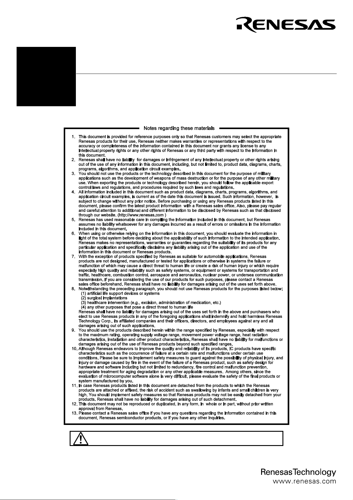
2. Package Components (See Figure 1)
Check to see if the R0E0100TNPFK00 package has all the
following contents before using this product.
(1) R0E0100TNPFK00 converter board........................... 1 pc.
(2) YQPACK100SD (made by Tokyo Eletech Corporation) ................1 pc.
(3) NQPACK100SD-ND
(4) YQ-GUIDE
(made by Tokyo Eletech Corporation) .....................4 pcs.
(made by Tokyo Eletech Corporation) ....... 1 pc.
(5) R0E0100TNPFK00 User's Manual (this manual)
3. Specifications
Table 1 Specifications
PLQP0100KB-A:
Applicable package
formerly 100P6Q-A
(100-pin 0.5mm pitch LQFP)
Insertion/removal
iterations of connector
50 times
guaranteed
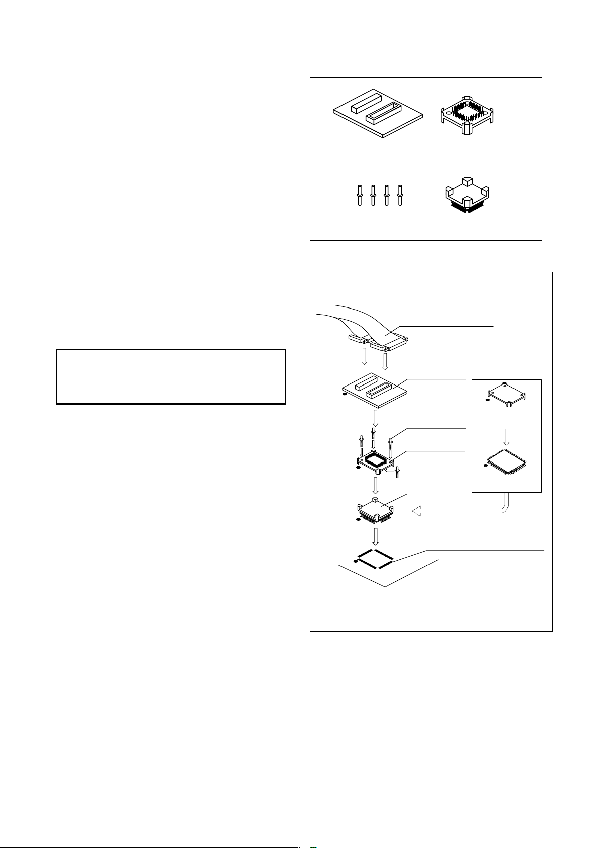
4. Usage (See Figure 2)
The R0E0100TNPFK00 can be used for debugging and
board-mounted evaluation in common by mounting the
NQPACK100SD-ND on the user system.
(1) For debugging
Mount the NQPACK100SD-ND on the foot pattern of the
user system and attach the YQPACK100SD on it. In
addition, connect the R0E0100TNPFK00 to the
YQPACK100SD, and then connect the flexible cable
R0E001000FLX10 of the emulator to the upper connector
of the R0E0100TNPFK00.
(2) For onboard evaluation
Mount an MCU with on-chip flash memory or one-time
PROM and the HQPACK100SD (not included) in order
on the NQPACK100SD-ND on the user system.
Before using the R0E0100TNPFK00, be sure to read "7.
Precautions" on page 4.
R0E0100TNPFK00
converter board
YQ-GUIDE (×4)
YQPACK100SD
NQPACK100SD-ND
Figure 1 Package components of the R0E0100TNPFK00
(1) For debugging
Flexible cable
R0E001000FLX10
(2) For on-board
R0E0100TNPFK00
YQ-GUIDE (×4)
YQPACK100SD
NQPACK100SD -ND
100-pin 0.5mm pitch
(PLQP0100KB-A) foot pattern
●: N o .1 p in
Be sure to align the pins.
evaluation
HQPACK100SD
(not included)
FLASH MCU, etc.
Figure 2 Usage of the R0E0100TNPFK00
(2/4)
Page 3

5. Connection Procedure (See Figure 3)
The procedure for connecting the R0E0100TNPFK00 is shown
below.
(1) Mount the NQPACK100SD-ND on the user system.
(2) Attach the YQPACK100SD on the NQPACK100SD-ND.
(3) Secure the four corners of the YQPACK100SD with the
YQ-GUIDEs.
● Do not use the screws included with the
YQPACK100SD for fixing the YQPACK100SD.
● Do NOT use the screwdriver included with the
NQPACK100SD-ND for fixing the YQ-GUIDEs. That
is used only for the HQPACK100SD.
(4) Mount the R0E0100TNPFK00 on the YQPACK100SD.
(5) Attach the flexible cable R0E001000FLX10 of the
emulator to the R0E0100TNPFK00.
Flexible cable
R0E001000FLX10
(5)
R0E0100TNPFK00
Use a slotted screwdriver.
(4)
YQ-GUIDE (×4)
YQPACK100SD
(3)
(2)
(1)
NQPACK100SD-ND
100-pin 0.5mm pitch
(PLQP0100KB-A) foot pattern
●: N o .1 pin
Be su re to align th e pins.
Figure 3 Connection procedure of the R0E0100TNPFK00
6. External Dimensions and a Sample Foot Pattern
37.00
R0E0100TNPFK00
REV.A
100
16.50
1
CN2
5051
100
1
CN1
50 51
MADE IN JAPAN
38.00
0.25
0.50
13.0
13.0
17.0
Figure 4 External dimensions and a sample foot pattern of the R0E0100TNPFK00
(3/4)
17.0
Unit: m m
Page 4

7. Precautions
CAUTION
Cautions to Be Taken for This Product:
z When connecting the YQPACK100SD, be sure to use the included YQ-GUIDEs.
z Do NOT use the screws included with the YQPACK100SD for connecting the YQPACK100SD.
IMPORTANT
Notes on This Product:
z We cannot accept any request for repair.
z For purchasing the NQPACK100SD-ND, YQPACK100SD and HQPACK100SD, contact the following:
Tokyo Eletech Corporation http://www.tetc.co.jp/e_index.htm
z For inquiries about the product or the contents of this manual, contact your local distributor.
Renesas Tools Homepage http://www.renesas.com/tools
8. Correspondence of Connectors CN1 and CN2
Table 2 Correspondence of the connectors
CN1 Pin No. IC1 CN1 Pin No. IC1 CN2 Pin No. IC1 CN2 Pin No. IC1
1
2
3
4
5 57 96 56 5
6 58 95 55 6
7 59 94 54 7
8 60 93 53 8
9 61 92 52 9
10 62 91 51 10
11 63 90 50 11
12 64 89 49 12
13 65 88 48 13
14 66 87 47 14
15
16 67 85 46 16
17 68 84 45 17
18 69 83 44 18
19 70 82 43 19
20 71 81 42 20
21 72 80 41 21
22 73 79 40 22
23 74 78 39 23
24 75 77 38 24
25 76 76 37 25
26
27 97 74 36 27
28 98 73 35 28
29 99 72 34 29
30 100 71 33 30
31 1 70 32 31
32 2 69 31 32
33 3 68 30 33
34 4 67 29 34
35 5 66 28 35
36 6 65 27 36
37
38 7 63 26 38
39 8 62 25 39
40 9 61 24 40
41 10 60 23 41
42 11 59 22 42
43 12 58 21 43
44 13 57 20 44
45 14 56 19 45
46 15 55 18 46
47 16 54 17 47
48
49
50
(-:No connection or signals in the emulator)
-
-
-
-
-
-
-
-
-
-
100
99
98
97
86
75
64
53
52
51
-
-
-
-
-
-
-
-
-
-
1
2
3
4
15
26
37
48
49
50
-
-
-
-
-
-
-
-
-
-
-
-
-
-
-
-
-
-
-
-
-
-
-
-
-
-
-
-
-
-
-
-
-
-
-
-
-
-
-
-
-
-
-
-
-
-
-
-
-
-
100
99
98
97
96
95
94
93
92
91
90
89
88
87
86
85 77
84 78
83 79
82 80
81 81
80 82
79 83
78 84
77 85
76 86
75
74 87
73 88
72 89
71 90
70 91
69 92
68 93
67 94
66 95
65 96
64
63
62
61
60
59
58
57
56
55
54
53
52
51
-
-
-
-
-
-
-
-
-
-
-
-
-
-
-
-
-
-
-
-
-
-
-
-
-
-
-
-
-
-
(4/4)
 Loading...