

Page 1
R0E001000EXT00
r
External Trigger Cable for the E100 Emulato
User’s Manual
CAUTION
Renesas Tools Homepage http://www.renesas.com/tools
Rev.1.00
Mar. 16, 2008
REJ10J1817-0100
If the requirements shown in the "CAUTION" sentences are ignored,
the equipment may cause personal injury or damage to the products.
(1/4)
Page 2
1. Outline
The external trigger cable R0E001000EXT00 allows tracing of
external signals and output of events through the external trigger
connector of the E100 emulator (R0E001000EMU00).
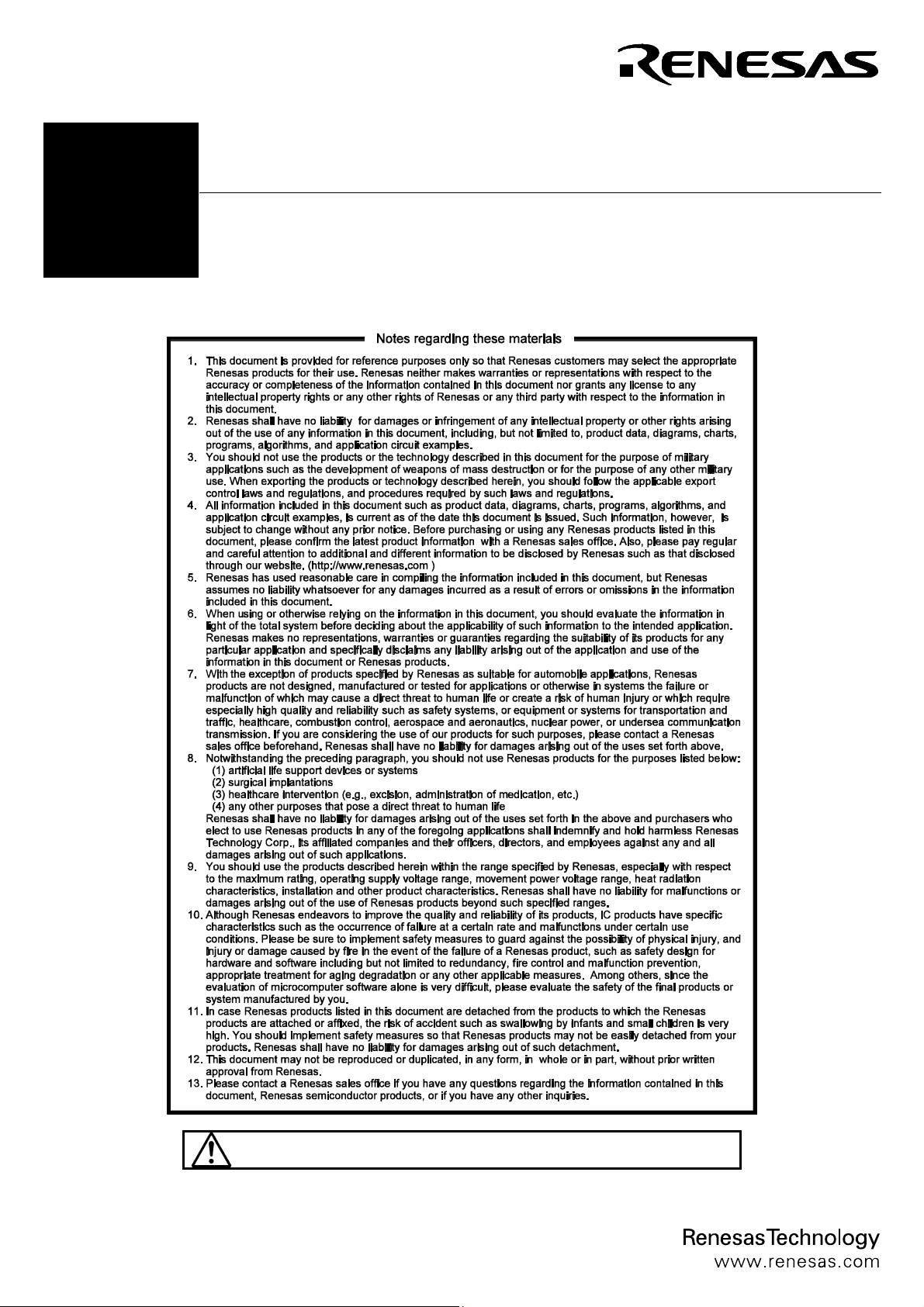
2. Package Components (See Figure 1)
Check to see if the R0E001000EXT00 package has all the
following contents before using this product.
(1) R0E001000EXTE0 board............................................ 1 pc.
(2) R0E001000EXTT0 board (with a cable) ............................1 pc.
(3) R0E001000FLX10 flexible cable................................ 1 pc.
(4) R0E001000EXT00 user's manual (this document)
R0E001000EXTE0 board
(E100 emulator side)
R0E001000FLX10
flexible cable
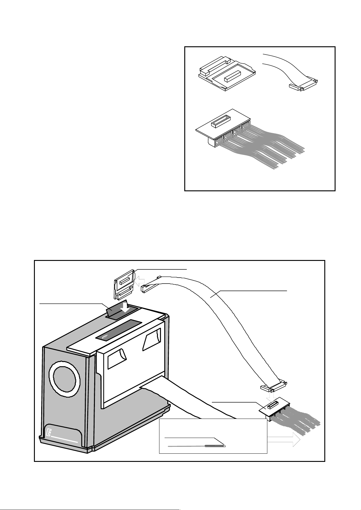
3. Usage (See Figure 2)
The usage of the external trigger cable R0E001000EXT00 is
shown in Figure 2.
Figure 1 Package Components of the R0E001000EXT
Procedure:
After checking that the power supplies for the E100 emulator and the user system are turned off, connect the external trigger cable
R0E001000EXT00 according to the following procedure.
(1) Connect R0E001000FLX10 to the R0E001000EXTE0 board.
(2) Open the lid (EXT) of the E100 emulator and connect the R0E001000EXTE0 board to the external trigger connector.
(3) Connect signals to the user-system connection sockets of R0E001000EXTT0.
(4) Connect R0E001000FLX10 to R0E001000EXTT0.
R0E001000EXTE0
(1)
R0E001000EXTT0 board with a cable
(user system side)
R0E001000FLX10
flexible cable
External trigger connector
5
6
0
3
5
E
0
R
1
H
I
0
G
H
P
E
R
0
F
E
O
M
R
U
M
L
A
A
N
T
O
C
E
R
S
Y
S
T
E
M
Figure 2 Usage of the R0E01000EXT00
(2)
0
0
U
C
M
0
(4)
R0E001000EXTT0
User-system connection sockets
(204351-1 made by AMP)
Size: 0.76 mm
(3)
(2/4)
Page 3

4 Connection with a User System
(See Figure 3)
(1) GND connection
The black wire connected to the R0E001000EXTT0 board
acts as a GND terminal. This wire must be connected to GND
of the user system.
(2) Trigger-signal correspondence table
Input and output attributes for trigger signals are specifiable
through settings in the emulator debugger. Table 1 shows the
correspondence between the [Trigger] section ([External
trigger cable]) on the [System] page of the [Configuration
Properties] dialog box of the emulator debugger and
identification numbers for the user-system connection sockets.
Figure 3 Connection with a User System
Table 1 Trigger-Signal Correspondence Table
Trigger Signal
Name
CLK I CN3-2 CLK
EXT0 I CN4-10 0
EXT1 I CN4-9 1
EXT2 I CN4-8 2
EXT3 I CN4-7 3
EXT4 I CN4-6 4
EXT5 I CN4-5 5
EXT6 I CN4-4 6
EXT7 I CN4-3 7
EXT8 I CN3-10 8
EXT9 I CN3-9 9
EXT10 I CN3-8 10
EXT11 I CN3-7 11
EXT12 I CN3-6 12
EXT13 I CN3-5 13
EXT14 I CN3-4 14
EXT15 I CN3-3 15
EXT16 I/O CN6-10 16
EXT17 I/O CN6-9 17
EXT18 I/O CN6-8 18
EXT19 I/O CN6-7 19
EXT20 I/O CN6-6 20
EXT21 I/O CN6-5 21
EXT22 I/O CN6-4 22
EXT23 I/O CN6-3 23
EXT24 I/O CN5-10 24
EXT25 I/O CN5-9 25
EXT26 I/O CN5-8 26
EXT27 I/O CN5-7 27
EXT28 I/O CN5-6 28
EXT29 I/O CN5-5 29
EXT30 I/O CN5-4 30
EXT31 I/O CN5-3 31
Input/Output R0E001000EXTT0
Connector Number
Identification Number for the User-System
Connection Socket
R0E001000EXTT0
Wires:
Black (GND) and gray (signal)
Identification number on the sticker
for each user-system connection socket
(3/4)
Page 4

5. Precautions
Notes on This Product:
z We cannot accept any request for repair.
z For inquiries about the product or the contents of this manual, contact your local distributor.
Renesas Tools Homepage http://www.renesas.com/tools
IMPORTANT
(4/4)
 Loading...