

Remotec Z-URC 550EU, ZXT-300EU User Manual
1
ZXT-300EU
(Z-Wave-to-AV
IR Extender)
Z-URCTM 550EU
(Z-Wave Enabled Universal
Remote Control
)

2
Table of Contents
Introduction.................................................... 4
Glossary .......................................................... 5
Z-URC
TM
550EU Operations ............................. 6
Configurations ................................................. 7
Description of Setup Keys.................................. 8
Group Control.................................................. 9
XpressZetup
TM
(Group Setup) ........................... 9
Group Operation .............................................. 11
Scene Control .................................................. 12
Scene Setup .................................................... 12
Scene Operation............................................... 14
Additional Device Setups................................. 14
Add/Delete Devices .......................................... 14
Add/Remove/Delete Devi ce/EP to/from a group ... 15
Assign Association for Two Devices .................... 17
Add/Delete All-On/All-Off functions .................... 20
Change Device Configuration ............................ 22
Advanced Z-Wave Network Setups.................. 23
Copying All Network and Device Information to a
Secondary Controller ........................................ 23
Copying Network Information to a Secondary
Controller........................................................ 24
Transferring All Network and Device Information
to a New Primary Controller (Primary shift) ......... 25
Transferring Only Network Information to a New
Primary Controller (Primary shift)....................... 26
Replicating All Network and Device Information
from a Primary Controller to your Z-URC
TM
550EU
(Learning Mode)............................................... 27
Listening Mode................................................. 28
Resetting Your Network..................................... 29
ZXT-300EU Operations ................................... 30
Configurations ................................................. 30
ZXT-300EU Information ................................... 31

3
Add/Delete Devices .......................................... 32
Add/Remove Device to/from a Simple AV channel 34
IR Code Setup ................................................. 36
IR Port Mapping ............................................... 37
IR Output Power .............................................. 38
AV Command Operation.................................... 40
IR Code Learning.............................................. 40
IR Code Learning on ZXT-300EU ........................ 40
IR Code Learning on Z-URC
TM
550EU .................. 42
Download the preset / learned IR code ............... 43
Reset ZXT-300EU to factory default.................... 44
INSTALLATION................................................ 45
MOUNTING THE ZXT-300EU TO A WALL .............. 45
WIRELESS INFORMATION ............................... 47
AUDIO/VIDEO SETUP AND OPERATION........... 48
Description of Audio/Video Control Key s.............. 49
AV Equipment Selection by Entering Device Code. 51
AV Equipment Selection by Searching through
the Library ...................................................... 52
Learning IR Commands..................................... 53
Operating the Z-URC
TM
550EU for AV Equipment .. 54
ADVANCED OPERATION FOR AV EQUIPMENT .. 56
Secondary Function .......................................... 56
IR Boost Mode ................................................. 56
Restore Factory Settings ................................... 57
MAINTENANCE................................................. 57
FREQUENTLY ASKED QUESTIONS .................... 57
Z-Wave Frequently Asked Questions................... 57
AV Control Frequently Asked Questions............... 60
TECHNICAL SPECIFICATIONS.......................... 61
CHECKING THE ACCESSORIES ......................... 63
WARNINGS...................................................... 64
4
Z-URC
TM
550EU
(Z-Wave Enabled Universal Remote Control)
ZXT-300EU
(
Z-Wave-to-AV IR Extender)
Operating Instructions
Introduction
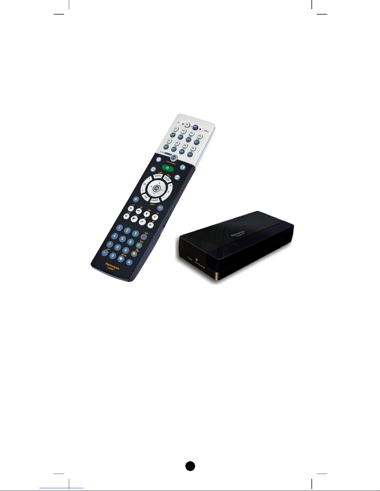
The Z-URC
TM
550EU Z-Wave AV Controller is a universal AV remote
and also a Z-Wave controller (Figure 1). As a universal remote, the ZURC
TM
550EU replaces all your AV remotes through its built-in IR
code database or IR code learning. As a Z-Wave controller, the ZURC
TM
550EU works with Z-Wave enabled devices, support multichannel command class devices and controls their on/off or up/down
individually, as a Group, or via a pre-configured Scene.
A perfect kit of Z-URC
TM
550EU and ZXT-300EU (Z-Wave-to-AV IR
Extender). It works with any Z-Wave compliant controller or gateway
by translating Z-Wave Simple AV command to IR control code.
User can set the IR code from the built-in code library of ZXT-300EU,
or use the learning function of ZXT-300EU through the simple UI of
Z-URC
TM
550EU. User can also download the preset code or learnt
command from Z-URC
TM
550EU to ZXT-300EU. User can enjoy the
fully wireless control in anywhere at home.
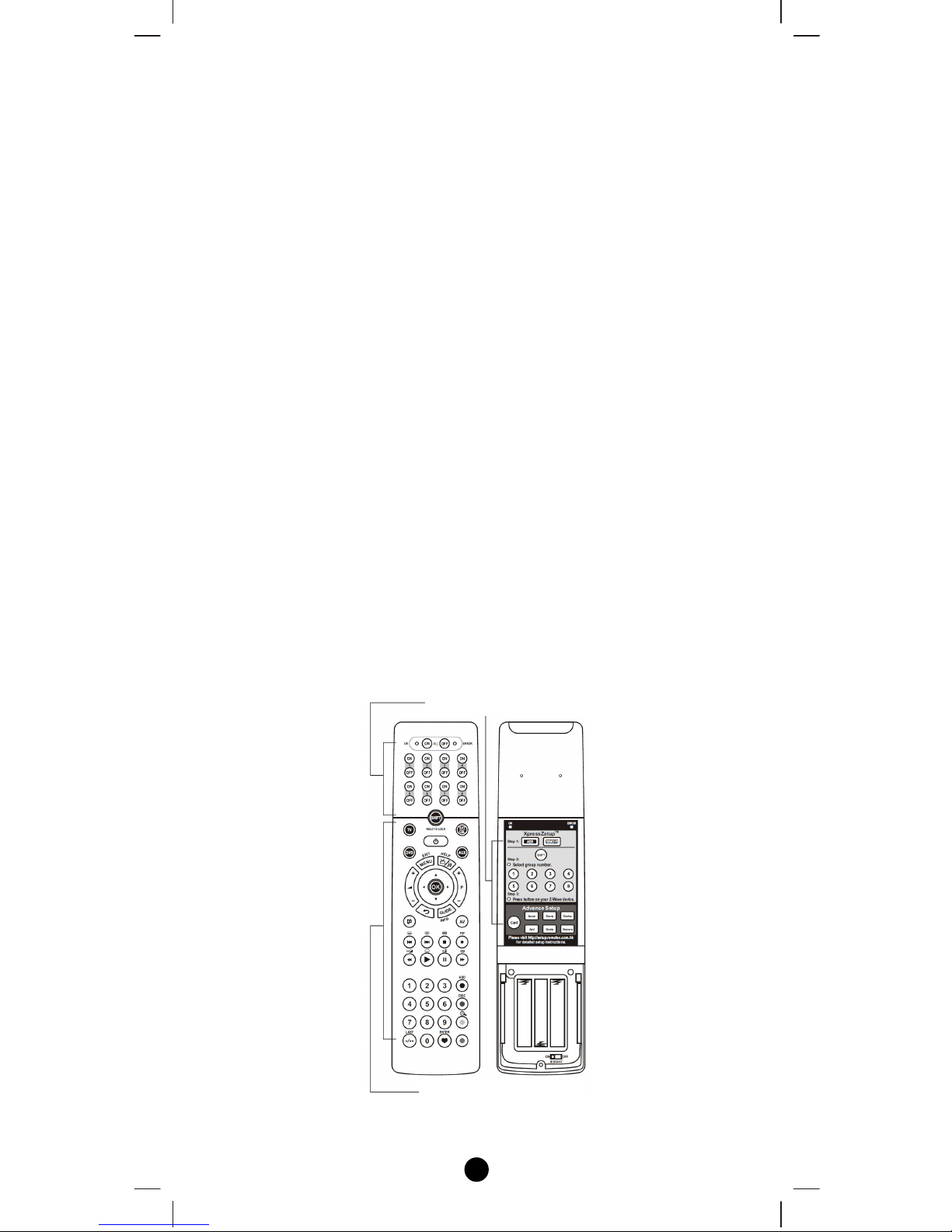
Figure 1 Z-URC
TM
550EU
Z-Wave control key (can be Group On/Off or Scene On/Off)
Audio visual control key
5
Glossary
Device or Node
Z-Wave enabled device that can be
controlled by the Z-URC
TM
.
Inclusion
Add a Z-Wave device to the network.
Exclusion
Delete a Z-Wave device from the network.
Remove
To take a device out of a group, scene or
association group while that device still
exists in the same Z-Wave network.
Z-Wave
Network
A collection of Z-Wave devices controlled
by primary and secondary controllers
operating on the same system. A Z-Wave
network has its own unique ID code so that
controllers not in the network cannot control
the system.
Primary
Controller
The first controller used to set up your
devices and network. Only the Primary
Controller can be used to include or delete
modules from a network. It is recommended
that you mark the primary controller for each
network for ease in modifying your network.
Secondary
Controller
A controller containing network information
about other modules within the network and
is used for controlling devices. Secondary
controllers are created from the Primary
Controller and cannot include or delete
modules to the network.
Inclusion
Controller
A controller containing network information
about other modules within the network and
is used for controlling devices. Inclusion
controllers are created from the Primary
Controller in a SIS enabled Z-Wave network.
Inclusion Controller has the ability to add
and remove devices from the network.
Scene
A collection of Z-Wave devices configured
to turn to a specific level, setting, mode, or
perform an operation. Scenes are usually
activated by a controller, timed event, or
specific conditions.
6
Z-URCTM 550EU Operations
Welcome to the world of home automation, your Z-URC
TM
550EU will
be able to control all the Z-Wave products around your house. The
following section will guide you through the set up processes for your
Z-URC
TM
550EU. Firstly there is the XpressZetupTM for beginner users
that do not have a large amount of Z-Wave products. Following is the
advanced set up that you will need to become familiar with as your ZWave network of products continues to expand.
Please note that all Z-Wave devices, light switches, dimmers, and
shutter switches made from various vendors are compatible with your
Z-URC
TM
550EU as long as they carry the Z-Wave logo:
(Please carefully read through the following then store the manual for
future reference.)
Before using the Z-URC
TM
550EU, please install the batteries:
• 3xAAA batteries are required for operation.
• Remove the battery cover on the back of your Z-URC
TM
550EU.
• Check the polarity of the batteries and the "+/-" marks inside the
battery compartment.
• Insert the batteries.
• Push the battery cover back in place.
L CAUTION (battery safety)
− Use new batteries of the recommended type and size only.
− Never mix used and new batteries together.
− To avoid chemical leaks, remove batteries from the Z-URC
TM
550EU if you do not intend to use the remote for an extended
period of time.
− Dispose of used batteries properly; do not burn or bury them.
7
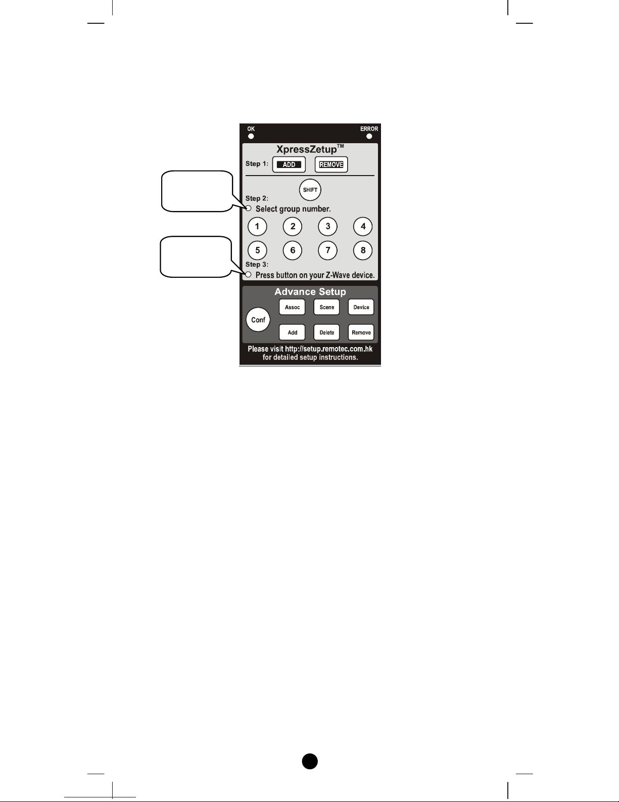
Configurations
Please open the configuration compartment then you can see the ZURC
TM
550EU setup keys (Figure 2).
Figure 2 Setup Keys of the Z-URC
TM
550EU
Status
LED
_A
Status
LED
_
B
8
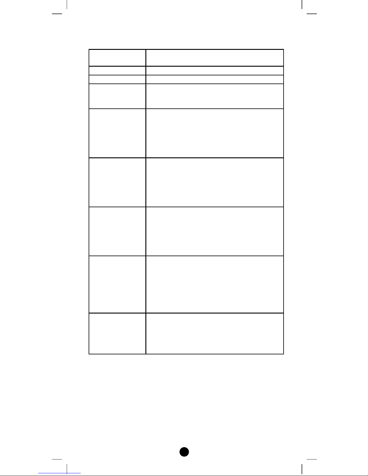
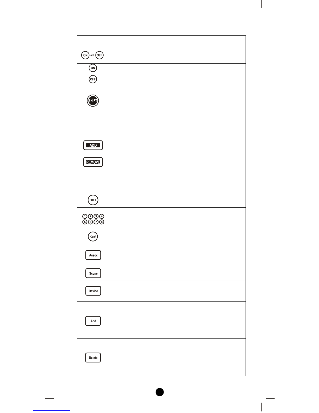
Description of Function Keys
Keys Functions
The All-On and All-Off keys are used for turns on
or off all Z-Wave devices in the device database.
The On and Off keys are used for the different ZWave groups and scenes control.
Press once to access secondary functions for the
next button. Press and hold to activate shift lock for
permanent use of shift functions. Press shift again to
release shift lock.
Note: The shift key allows you access group's shift 1
through shift 8 giving you a total of 16 groups.
The ADD and REMOVE keys are used during
XpressZetup
TM
process.
ADD key will perform two functions:
• Add a target device to Z-Wave network, also
known as INCLUSION;
• Add the device to the assigned GROUP.
REMOVE key will only remove the target device
from its assigned group but will not exclude it from
the network.
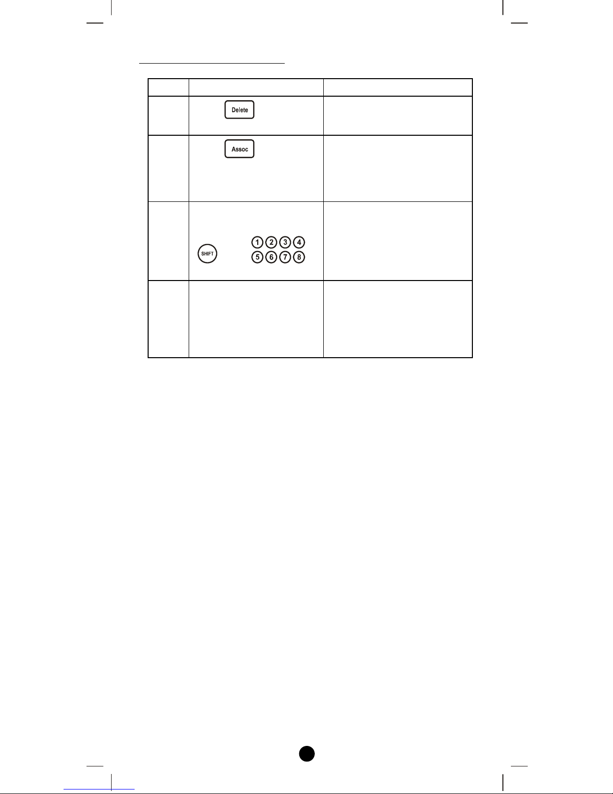
This SHIFT key is used for accessing group
numbers 9 to 16 while programming your devices.
These are your group numbers 1 through 8 and also
become group numbers 9 through 16 when
combined with the SHIFT key.
This Configuration key is used during the
ADVANCED SETUP process.
This Association key is used in conjunction with
Add, Delete or Remove keys in order to assign
association groups.
This Scene key is used in conjunction with Add,
Delete or Remove keys in order to program scenes.
This Device key is used in conjunction with Add,
Delete keys in order to include or exclude devices to
the network.
This Add key is used in the Advance Setup to:
• Add a device to the network (inclusion);
• Add a device to a group;
• Add a device to an association group;
• Add a device to a scene.
This Delete key is used in the Advance Setup to:
• Delete a device from the network (exclusion);
• Delete a group;
• Delete an association group;
• Delete a scene.
9
This Remove key is used in the Advance Setup to:
• Remove a device from a group;
• Remove a device from an association group;
• Remove a device from a scene.
Group Control
The Z-URC
TM
550EU enables you to control single or multiple ZWave devices with the press of a button. For example, you can group
all your bedroom lights together so that all of them will turn on with
the press of a button.
You can control up to 16 groups (Group On/Off) with your Z-URC
TM
550EU. Each Group supports up to 32 Z-Wave devices or End-point
(EP) and supports up to 232 Z-Wave devices in a network.
Remark: There are total 16 groups of on/off keys which are shared by
Scene and Group, for example, if you used 6 groups as Group, there
are 10 groups on/off keys left for Scene, and vise versa.
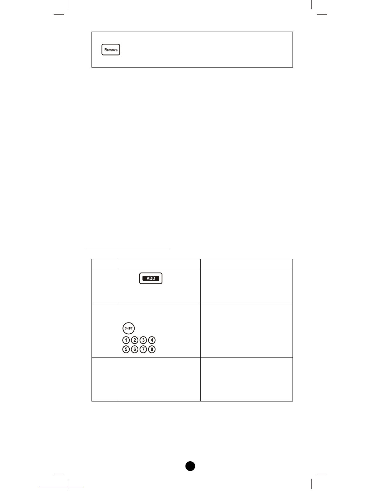
XpressZetupTM (Group Setup)
Including Device to a Group
Step Setup Key LED Indication Status
1
Press in
XpressZetup
TM
area
• “OK" LED on
• “LED_A" flashes
rapidly
2
Select a group number
from 1 to 16 (1-8 or
1-8)
• “LED_A" off
• “LED_B" flashes
rapidly
3
Press the program button
on the target device
• “OK" LED flashes
once then turns off
• “LED_B" off
• Group setup completed
Note 1: If you cannot add your Z-Wave device, this device might have
been included in another Z-Wave network. In this case, please delete
this device following the steps in the [Deleting Device from the
Network] section then add this device again.
10
Note 2: XpressZetup
TM
cannot support “Multi-Channel Device”, please
refer to [Adding Device to the Network] and [Adding Device/End-point
to a group] for normal setup procedure.
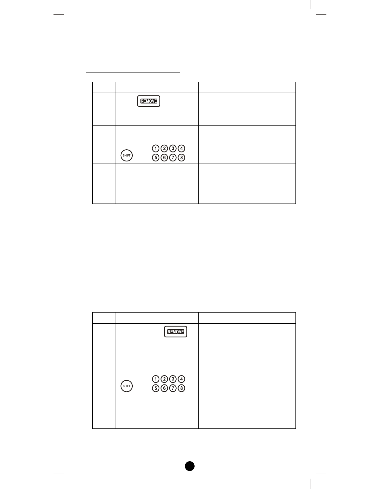
Removing Device from a Group
Step Setup Key LED Indication Status
1
Press in
XpressZetup
TM
area
• “OK" LED on
• “LED_A" flashes
rapidly
2
Select a group number
from 1 to 16 (1-8 or
1-8)
• “LED_A" off
• “LED_B" flashes
rapidly
3
Press the program button
on the target device
• “OK" LED flashes once
then turns off
• Device been removed from
the Group successfully
Note 1: If the ERROR LED turns on or flashes, meaning the setup
process is failed. Please redo the process.
Note 2: XpressZetup
TM
cannot support “Multi-Channel Device”, please
refer to [Removing Device/End-point from a group] for normal setup
procedure.
Note 3: This process will only remove the target device from its
assigned group but will not exclude it from the network.
Removing all Devices from a Group
Step Setup Key LED Indication Status
1
Press and hold
in XpressZetup
TM
area
• “OK" LED on
• “LED_A" flashes
rapidly
2
Select a group number
from 1 to 16 (1-8 or
1-8)
• “LED_A" off
• “LED_B" flashes
rapidly
• “OK" LED flashes once
then turns off
• Device been deleted from
the Group successfully
Note 1: If the ERROR LED turns on or flashes, meaning the setup
process is failed. Please redo the process.
11
Note 2: This process will only remove the group devices from its
assigned group but will not exclude it from the network.
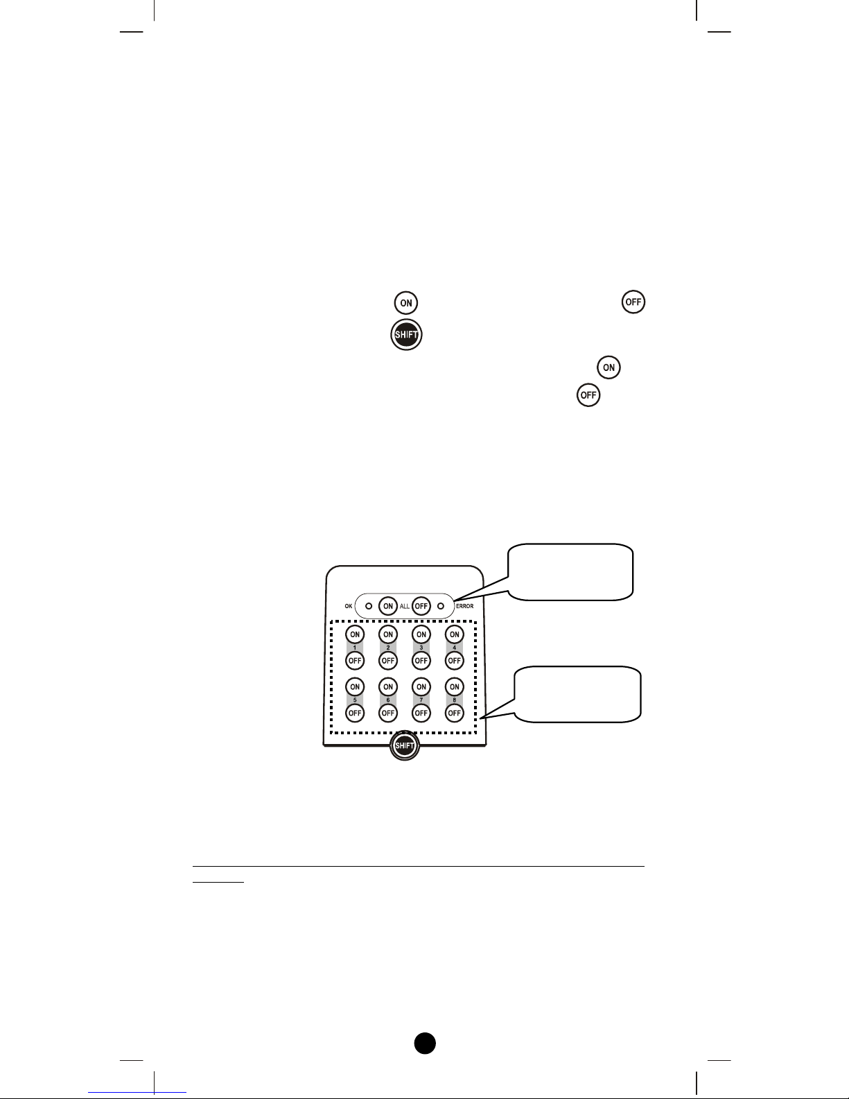
Group Operation
After adding devices to your Z-URC
TM
550EU using XpressZetupTM,
you can turn the device on/off or up/down via the corresponding group
control keys in front (Figure 3).
• For on/off switches, press key to turn on the devices and
key to turn them off. (use to extend 16 groups On/Off)
• To operate dimmer switches and curtain motors, hold the key
to open the curtain or dim up the light. By holding the key you
can retract the curtain or dim down the light.
• You can turn on all the devices in the network by pressing All-On
key and turn them off via All-Off key.
• The green “OK" LED flashes when the operation is successful,
and the red ERROR LED flashes when it’s failed.
Figure 3 Group Control Keys of the Z-URC
TM
550EU
By Advance Setup Process
(For advanced users to get the full flexibility offered by the Z-URCTM
550EU)
The Z-URC
TM
550EU remote is able to be set up with different
concepts such as Group, Scene, Association Group and Network.
These concepts are all setup on the underside of your Z-URC
TM
550EU
and operated with the corresponding number on the topside of the
remote.
Group
Control Keys
All On/Off
Keys
12
Scene Control
Z-Wave Scenes are used for setting up multiple devices in the same
way as a group but in addition to groups, scenes also control dimmer
lights that you can set to different levels depending on the situation.
For example you can have the scene set to low brightness for watching
a movie or going to bed or alternatively set the lights brighter when
reading or working. After the scene has been programmed it will work
with the corresponding ON OFF key on the top side of the remote.
You can control up to 16 scenes (Scene On/Off) with your Z-URC
TM
550EU. Each Scene supports up to 32 Z-Wave devices or End-point
(EP) and supports up to 232 Z-Wave devices in a network.
Remark: There are total 16 groups of on/off keys which are shared by
Scene and Group, for example, if you used 6 groups as Group, there
are 10 groups on/off keys left for Scene, and vise versa.
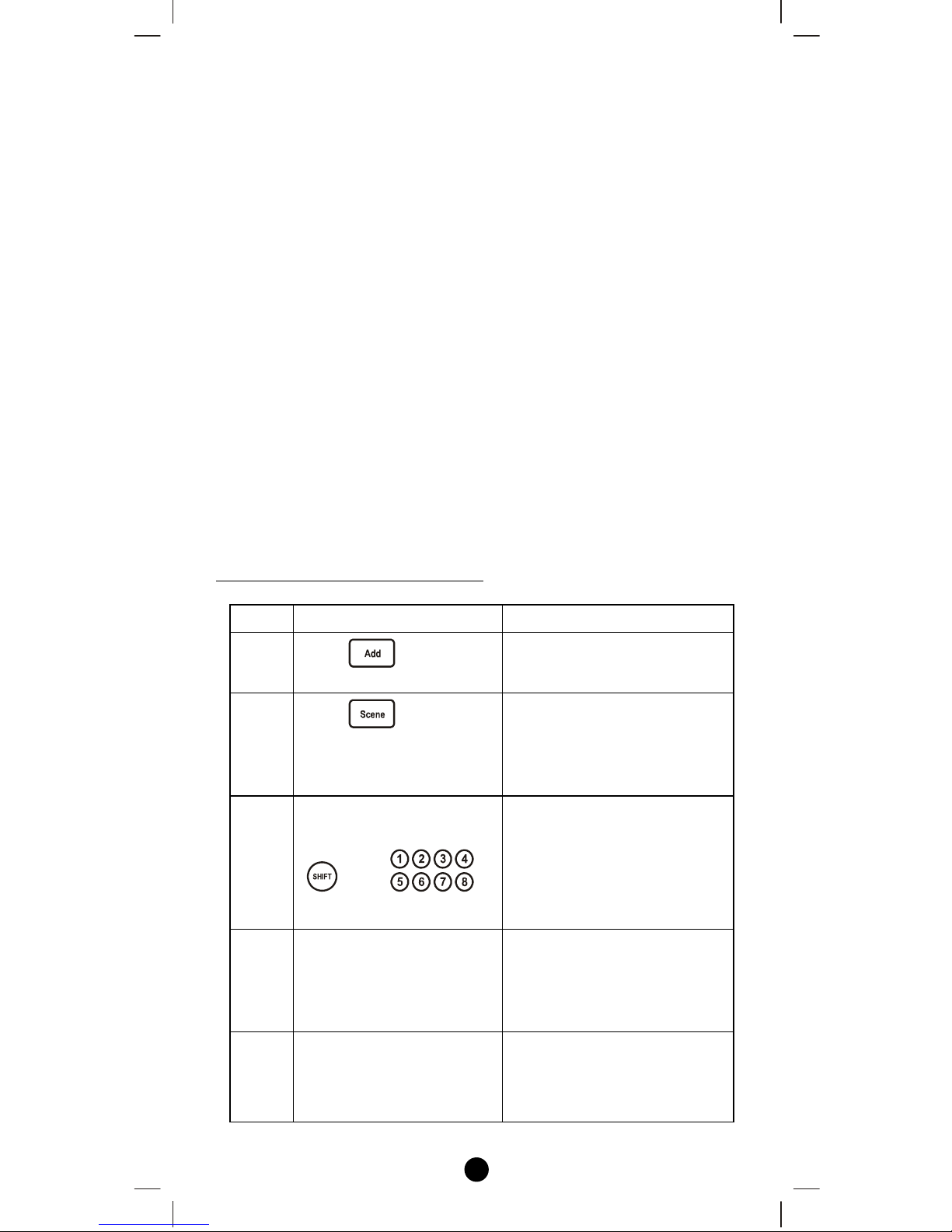
Scene Setup
Adding Device/End-point to a Scene
Step Setup Key LED Indication Status
1
Press in Advance
Setup
• The “OK" light turns
on
2
Press
• “OK" LED flashes
once and stays on
• “LED_A" flashes
slowly
3
Select a scene number
from 1 to 16 (1-8 or
1-8)
• “OK" LED flashes
once and stays on
• “LED_A" off
• “LED_B" flashes
slowly
4
Press the program/EP
button on the target
device
• “OK" LED flashes
once and stays on
• “LED_B" keep
blinking slowly
5
Adjust the target device
on/off or dim level with
its program button, to the
desired status
-
13
6
Press
• “OK" LED flashes
once then turns off
• “LED_B" off
• The current status of the
device will be learned
and saved to a scene
successfully
Note 1: Your target device must be included in the network before this
setup procedure, please refer to [Adding Device to the Network]
section.
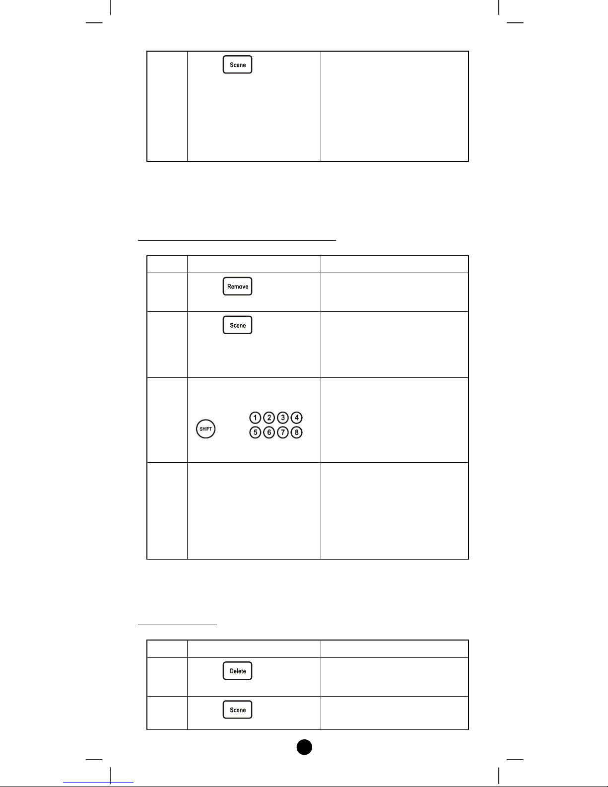
Removing Device/End-point from a Scene
Step Setup Key LED Indication Status
1
Press in Advance
Setup
• The “OK" light turns
on
2
Press
• “OK" LED flashes
once and stays on
• “LED_A" flashes
slowly
3
Select a scene number
from 1 to 16 (1-8 or
1-8)
• “OK" LED flashes
once and stays on
• “LED_A" off
• “LED_B" flashes
slowly
4
Press the program/EP
button on the target
device
• the “OK" light stays
on then flashes once and
turns off
• “LED_B" off
• Device removed from the
scene successfully
Note 1: This process will only remove the target device/EP from its
assigned scene but will not exclude it from the network.
Deleting a Scene
Step Setup Key LED Indication Status
1
Press in Advance
Setup
• The “OK" light turns
on
2 Press
• “OK" LED flashes
once and stays on
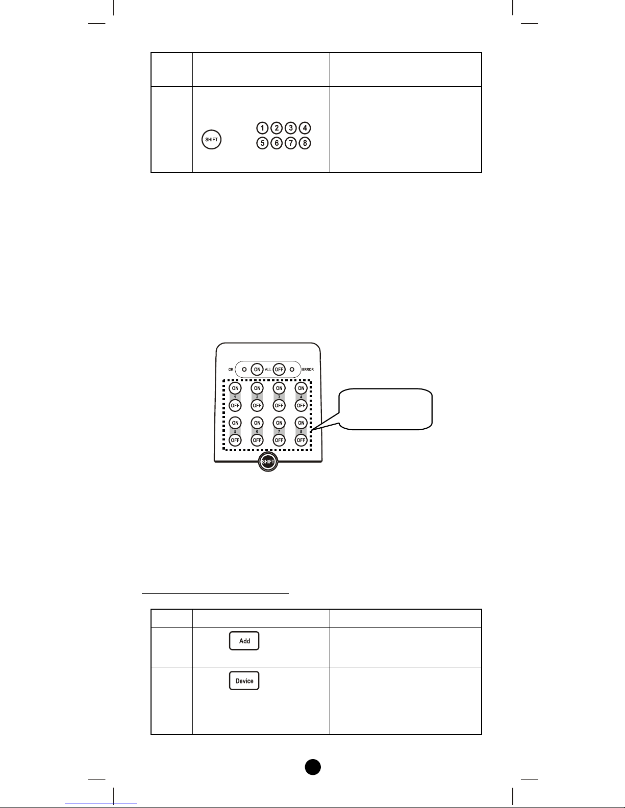
14
• “LED_A" flashes
slowly
3
Select a scene number
from 1 to 16 (1-8 or
1-8)
• “OK" LED flashes
once then turns off
• “LED_A" off
• Scene deleted from the
scene successfully
Note 1: This process will only remove the scene devices/EPs from its
assigned scene but will not exclude it from the network.
Scene Operation
After the scene setup is done, you can trigger the desired scene via
scene control keys in front panel of the Z-URC
TM
550EU. (Figure 4)
The green “OK" LED flashes when the operation is successful, and
the red ERROR LED flashes when it’s failed.
Figure 4 Scene Control Keys of the Z-URC
TM
550EU
Additional Device Setups
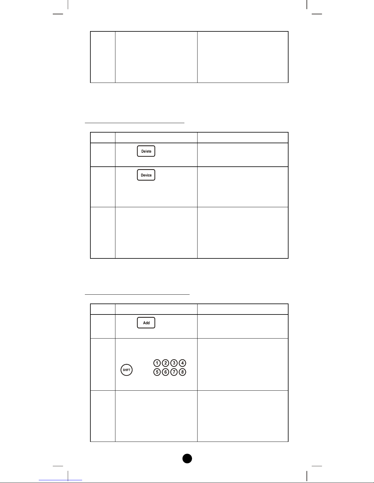
Add/Delete Devices
Adding Device to the Network
Step Setup Key LED Indication Status
1
Press in Advance
Setup
• The “OK" light turns
on
2
Press
• “OK" LED flashes
once and stays on
• “LED_B" flashes
slowly
Scene
Control Ke
y
s
15
3
Press the program button
on the target device
• “OK" LED flashes
once then turns off
• “LED_B" off
• Device inclusion
completed
Note 1: This step can be skipped if the device is already included in the
network.
Deleting Device from the Network
Step Setup Key LED Indication Status
1
Press in Advance
Setup
• The “OK" light turns
on
2
Press
• “OK" LED flashes
once and stays on
• “LED_B" flashes
slowly
3
Press the program button
on the target device
• “OK" LED flashes
once then turns off
• “LED_B" off
• Device exclusion
completed
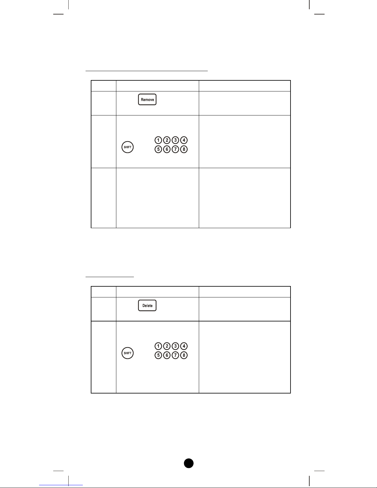
Add/Remove/Delete Device/End-point to/from a group
Adding Device/End-point to a group
Step Setup Key LED Indication Status
1
Press in Advance
Setup
• The “OK" light turns
on
2
Select a group number
from 1 to 16 (1-8 or
1-8)
• “OK" LED flashes
once and stays on
• “LED_A" off
• “LED_B" flashes
slowly
3
Press the program/EP
button on the target
device
• “OK" LED flashes
once then turns off
• “LED_B" off
• Add Device/End-point to
a group completed
16
Note 1: Your target device must be included in the network before this setup
procedure, please refer to [Adding Device to the Network] section.
Removing Device/End-point from a gr oup
Step Setup Key LED Indication Status
1
Press in Advance
Setup
• The “OK" light turns
on
2
Select a group number
from 1 to 16 (1-8 or
1-8)
• “OK" LED flashes
once and stays on
• “LED_A" off
• “LED_B" flashes
slowly
3
Press the program/EP
button on the target
device
• “OK" LED flashes
once then turns off
• “LED_B" off
• Remove Device/End-
point from a group
completed
Note 1: This process will only remove the target device/EP from its
assigned group but will not exclude it from the network.
Deleting a group
Step Setup Key LED Indication Status
1
Press in Advance
Setup
• The “OK" light turns
on
2
Select a group number
from 1 to 16 (1-8 or
1-8)
• “OK" LED flashes
once and stays on
• “LED_A" off
• “LED_B" flashes
slowly
• Delete a group
completed
Note 1: This process will only remove the group devices/EPs from its
assigned group but will not exclude it from the network.
17
Assign Association for Two Devices
The Z-URC
TM
550EU can be used to assign one device to
automatically interact directly with another device.
For example you can assign a door sensor (primary node) to turn on the
light switch (secondary node) when the door is opened.
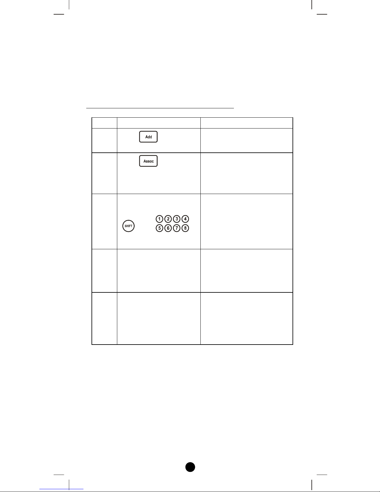
Adding Device/End-point to an Association Group
Step Setup Key LED Indication Status
1
Press in Advance
Setup
• The “OK" light turns
on
2
Press
• “OK" LED flashes
once and stays on
• “LED_A" flashes
slowly
3
Select a group number
from 1 to 16 (1-8 or
1-8)
• “OK" LED flashes
once and stays on
• “LED_A" off
• “LED_B" flashes
slowly
4
Press the program/EP
button on the secondary
device (e.g. light switch)
• “OK" LED flashes
once and stays on
• “LED_B" flashes once
and keep blinking slowly
5
Press the program/EP
button on the primary
device (e.g. door sensor)
• “LED_B" turns off
• “OK" LED flashes
once then turns off
• Assigning association
completed
Note 1: Your target device must be included in the network before this
setup procedure, please refer to [Adding Device to the Network]
section.
18
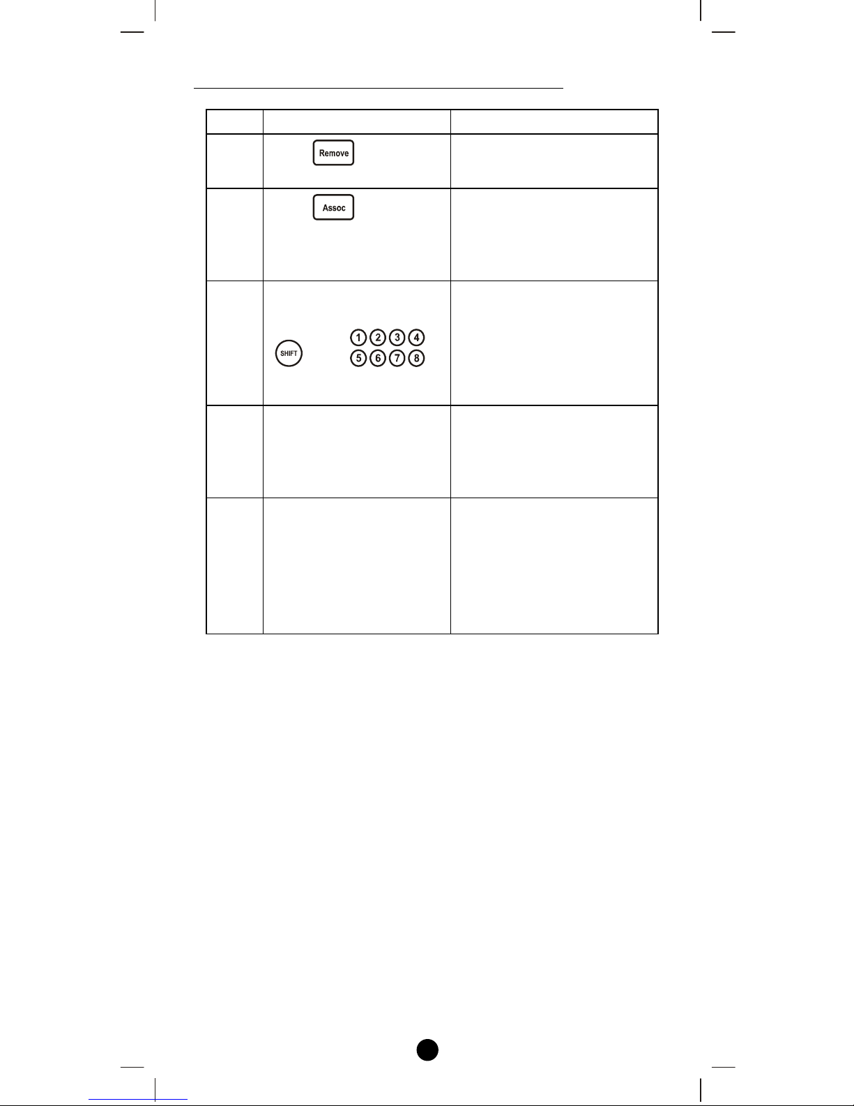
Removing Device/End-point from an Association Group
Step Setup Key LED Indication Status
1
Press in Advance
Setup
• The “OK" light turns
on
2
Press
• “OK" LED flashes
once and stays on
• “LED_A" flashes
slowly
3
Select a group number
from 1 to 16 (1-8 or
1-8)
• “OK" LED flashes
once and stays on
• “LED_A" off
• “LED_B" flashes
slowly
4
Press the program/EP
button on the secondary
device (e.g. light switch)
• “OK" LED flashes
once and stays on
• “LED_B" flashes once
and keep blinking slowly
5
Press the program/EP
button on the primary
device (e.g. door sensor)
• “LED_B" turns off
• “OK" LED flashes
once then turns off
• Device removed from the
association group
successfully
Note 1: This process will only remove the target device/EP from its
assigned association group but will not exclude it from the network.
19
Deleting an Association Group
Step Setup Key LED Indication Status
1
Press in Advance
Setup
• The “OK" light turns
on
2
Press
• “OK" LED flashes
once and stays on
• “LED_A" flashes
slowly
3
Select a group number
from 1 to 16 (1-8 or
1-8)
• “OK" LED flashes
once and stays on
• “LED_A" off
• “LED_B" flashes
slowly
4
Press the program/EP
button on the primary
device (e.g. door sensor)
• “LED_B" turns off
• “OK" LED flashes
once then turns off
• Deleting the association
group successfully
Note 1: This process will only remove the group devices/EPs from its
assigned association group but will not exclude it from the network.
20
Add/Delete All-On/All- Off functions
If desired, specific devices can be setup to ignore the All-On and AllOff commands.
The four possible responses are:
• It will respond to All-On and the All-Off commands (default).
• It will not respond to All-On and All-Off commands.
• It will respond to the All-Off command but will not respond to the
All-On command.
• It will respond to the All-On command but will not respond to the
All-Off command
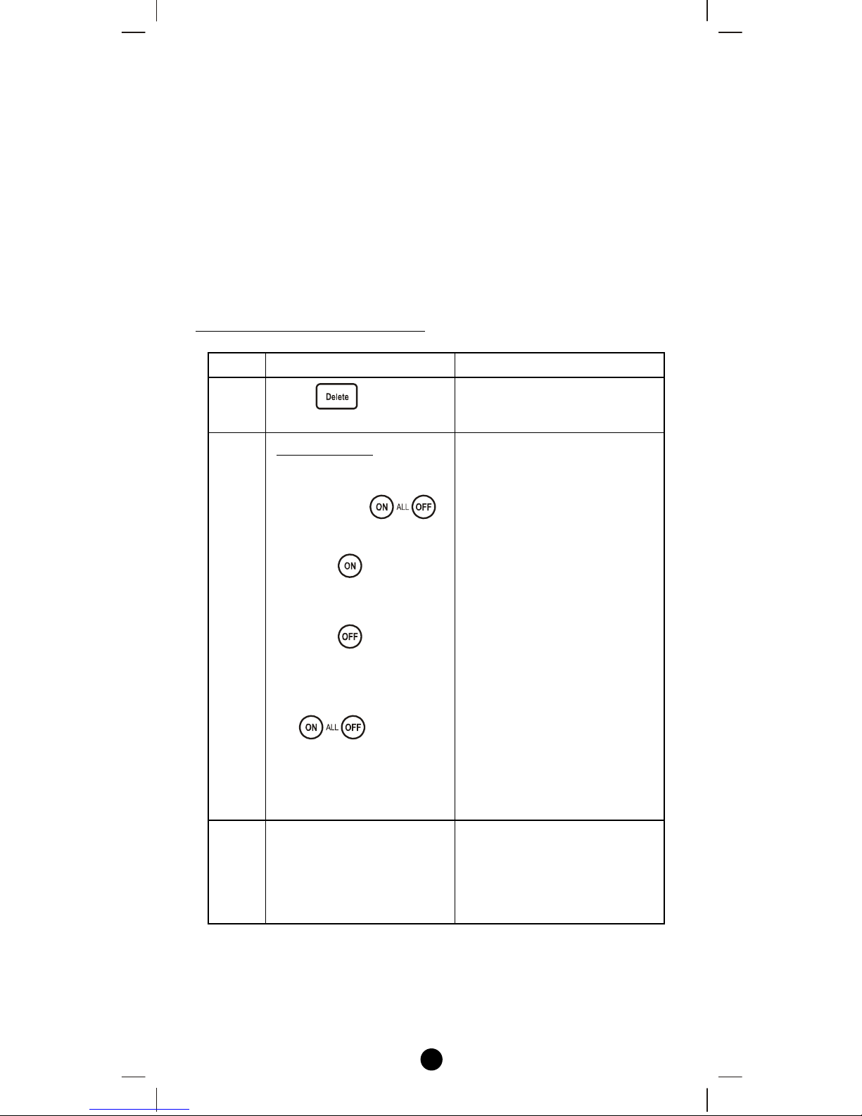
Deleting Devices from All Control
Step Setup Key LED Indication Status
1
Press in Advance
Setup
• The “OK" light turns
on
2
Press and hold
the key
for 2 seconds which you
want to delete from the
front top side
Example:
i) Press key to
delete from all-on
function,
ii) Press key to
delete from all-off
function,
iii) Press and hold
keys
simultaneously for 2
seconds to delete
from both all-on and
all-off function.
• “LED_B" flashes
slowly
3
Press the program button
on the target device
• “LED_B"turns off
• “OK" LED flashes
once then turns off
• Delete Device from All
Control successfully
 Loading...