

Page 1

Electrical wiring
REMKO series WSP
Brine- heat pump
Instructions for Technicians
WSP 80, WSP 110, WSP 140, WSP 180
0160-2017-05 Edition 2, en_GB
Read the instructions prior to performing any task!
Page 2
Read these operating instructions carefully before commissioning / using this device!
These instructions are an integral part of the system and must
always be kept near or on the device.
Subject to modifications; No liability accepted for errors or misprints!
Translation of the original
Page 3

Table of contents
1 Safety and usage instructions............................................................................................................. 4
1.1 General safety notes....................................................................................................................... 4
1.2 Identification of notes...................................................................................................................... 4
1.3 Personnel qualifications.................................................................................................................. 4
1.4 Dangers of failure to observe the safety notes................................................................................ 4
1.5 Safety-conscious working............................................................................................................... 4
1.6 Safety notes for the operator........................................................................................................... 5
1.7 Safety notes for installation, maintenance and inspection.............................................................. 5
1.8 Unauthorised modification and changes......................................................................................... 5
1.9 Intended use................................................................................................................................... 5
1.10 Warranty........................................................................................................................................ 5
1.11 Transport and packaging............................................................................................................... 6
1.12 Environmental protection and recycling........................................................................................ 6
2 Electrical wiring - General.................................................................................................................... 7
2.1 System layout.................................................................................................................................. 7
2.2 General notes.................................................................................................................................. 7
2.3 Electrical connection, heat pump.................................................................................................... 8
2.4 Connection of sensors and probes................................................................................................ 11
2.5 Electrical configuration - I/O module............................................................................................. 13
2.6 Terminal assignment / legend....................................................................................................... 14
3 Electrical wiring WSP......................................................................................................................... 16
3.1 Overview of electrical connecting lines......................................................................................... 16
3.2 Overview of terminal assignment.................................................................................................. 17
4 Circuit diagrams.................................................................................................................................. 18
5
Index..................................................................................................................................................... 25
3
Page 4
REMKO series WSP
1 Safety and usage
instructions
1.1 General safety notes
Carefully read the operating manual before commissioning the units for the first time. It contains
useful tips and notes such as hazard warnings to
prevent personal injury and material damage.
Failure to follow the directions in this manual not
only presents a danger to people, the environment
and the system itself, but will void any claims for
.
liability
Keep this operating manual and the refrigerant
data sheet near to the units.
1.2 Identification of notes
This section provides an overview of all important
safety aspects for proper protection of people and
safe and fault-free operation.The instructions and
safety notes contained within this manual must be
observed in order to prevent accidents, personal
injury and material damage.
Notes attached directly to the units must be
observed in their entirety and be kept in a fully
legible condition.
Safety notes in this manual are indicated by symbols. Safety notes are introduced with signal words
which help to highlight the magnitude of the danger
in question.
DANGER!
CAUTION!
This combination of symbol and signal word
warns of a potentially hazardous situation,
which if not avoided may cause injury or material and environmental damage.
NOTICE!
This combination of symbol and signal word
warns of a potentially hazardous situation,
which if not avoided may cause material and
environmental damage.
This symbol highlights useful tips and recommendations as well as information for efficient
and fault-free operation.
1.3 Personnel qualifications
Personnel responsible for commissioning, operation, maintenance, inspection and installation must
be able to demonstrate that they hold a qualification which proves their ability to undertake the
work.
Contact with live parts poses an immediate
danger of death due to electric shock. Damage
to the insulation or individual components may
pose a danger of death.
DANGER!
This combination of symbol and signal word
warns of a situation in which there is immediate
danger
cause serious injury.
This combination of symbol and signal word
warns of a potentially hazardous situation,
which if not avoided may be fatal or cause
serious injury
, which if not avoided may be fatal or
WARNING!
.
1.4
Dangers of failure to observe the safety notes
Failure to observe the safety notes may pose a risk
to people, the environment and the units. Failure to
observe the safety notes may void any claims for
damages.
In particular, failure to observe the safety notes
may pose the following risks:
n The failure of important unit functions.
n The failure of prescribed methods of mainte-
nance and repair
n Danger to people on account of electrical and
mechanical effects.
.
1.5 Safety-conscious working
The safety notes contained in this manual, the
existing national regulations concerning accident
prevention as well as any internal company
working, operating and safety regulations must be
observed.
4
Page 5

1.6 Safety notes for the operator
The operational safety of the units and components is only assured providing they are used as
intended and in a fully assembled state.
n The units and components may only be set up,
installed and maintained by qualified personnel.
n Protective covers (grille) over moving parts
must not be removed from units that are in
operation.
n Do not operate units or components with
obvious defects or signs of damage.
n Contact with certain unit parts or components
may lead to burns or injury
n The units and components must not be
exposed to any mechanical load, extreme
levels of humidity or extreme temperature.
n Spaces in which refrigerant can leak sufficient
to load and vent. Otherwise there is danger of
suffocation.
n All housing parts and device openings, e.g. air
inlets and outlets, must be free from foreign
objects, fluids or gases.
n The units must be inspected by a service tech-
nician at least once annually. Visual inspections and cleaning may be performed by the
operator when the units are disconnected from
the mains.
.
1.7 Safety notes for installation,
maintenance and
inspection
n The units and components must be kept at an
adequate distance from flammable, explosive,
combustible, abrasive and dirty areas or
atmospheres.
n Safety devices may not be modified or
bypassed.
Unauthorised modification
1.8
and changes
Modifications or changes to units and components
are not permitted and may cause malfunctions.
Safety devices may not be modified or bypassed.
Original replacement parts and accessories
authorised by the manufactured ensure safety
use of other parts may invalidate liability for
resulting consequences.
. The
1.9 Intended use
Depending on the model, the equipment and the
additional fittings with which it is equipped is only
intended to be used as an air-conditioner for the
purpose of cooling or heating the air in an
enclosed room.
Any different or additional use shall be classed as
non-intended use. The manufacturer/supplier
assumes no liability for damages arising from such
use. The user bears the sole risk in such cases.
Intended use also includes working in accordance
with the operating and installation instructions and
complying with the maintenance requirements.
n Appropriate hazard prevention measures must
be taken to prevent risks to people when performing installation, repair
cleaning work on the units.
n The setup, connection and operation of the
units and its components must be undertaken
in accordance with the usage and operating
conditions stipulated in this manual and comply
with all applicable regional regulations.
n The heat pump must be connected to the heat
source and heating or cooling system in
accordance with the relevant regulations.
n Regional regulations and laws as well as the
Water Ecology Act (WHG) must be observed.
n The power supply should be adapted to the
requirements of the units.
n Units may only be mounted at the points pro-
vided for this purpose at the factory. The units
may only be secured or mounted on stable
structures, walls or floors.
n Mobile units must be set up securely on suit-
able surfaces and in an upright position. Stationary units must be permanently installed for
operation.
n The units and components should not be oper-
ated in areas where there is an increased risk
of damage. Observe the minimum clearances.
, maintenance or
Under no circumstances should the threshold
values specified in the technical data be exceeded.
1.10 Warranty
For warranty claims to be considered, it is essential
that the ordering party or its representative complete and return the "certificate of warranty" to
REMKO GmbH & Co. KG at the time when the
units are purchased and commissioned.
The warranty conditions are detailed in the "General business and delivery conditions". Furthermore, only the parties to a contract can conclude
special agreements beyond these conditions. In
this case, contact your contractual partner in the
first instance.
5
Page 6
REMKO series WSP
1.11 Transport and packaging
The devices are supplied in a sturdy shipping con-
. Please check the equipment immediately
tainer
upon delivery and note any damage or missing
parts on the delivery and inform the shipper and
your contractual partner. For later complaints can
not be guaranteed.
WARNING!
Plastic films and bags etc. are dangerous
toys for children!
Why:
- Leave packaging material are not around.
- Packaging material may not be accessible to
children!
1.12 Environmental protection and recycling
Disposal of packaging
All products are packed for transport in environmentally friendly materials. Make a valuable contribution to reducing waste and sustaining raw materials. Only dispose of packaging at approved
collection points.
Disposal of equipment and components
Only recyclable materials are used in the manufacture of the devices and components. Help protect
the environment by ensuring that the devices or
components (for example batteries) are not disposed in household waste, but only in accordance
with local regulations and in an environmentally
safe manner
cling specialists or at collection points.
, e.g. using certified firms and recy-
6
Page 7
2 Electrical wiring - General
A
3
2
D
5
4
1
C
B
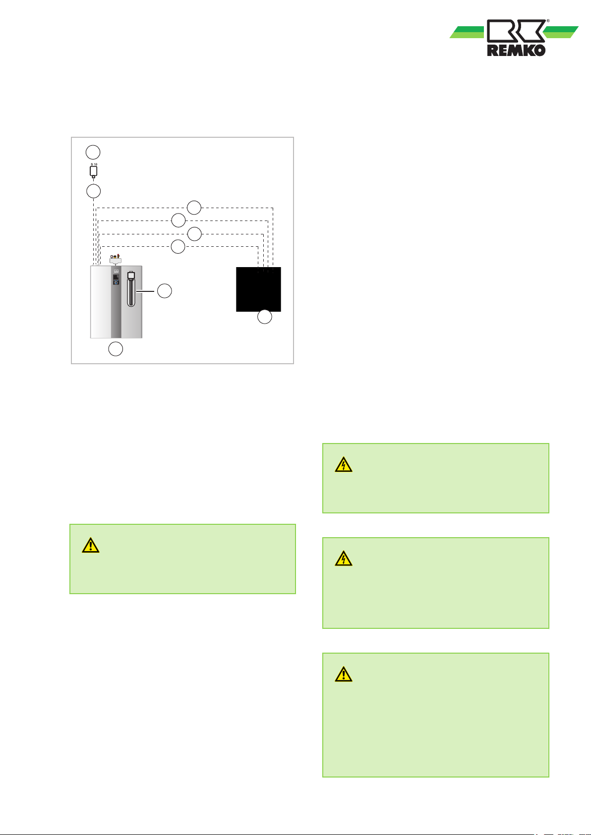
2.1 System layout
Fig. 1: System layout
A: Heat pump
B: Sub-distribution (provided by the customer)
C: Electrical heating coil
D: External probe
1: Power supply, heat pump
2: Power supply, auxiliary heater
3: Power supply, Smart Control controller
4: Potential-free power utility signal for Smart-
Control
5: Probe cable, external probe
2.2 General notes
n It is necessary to lay multiple power supply
lines from the distribution system to the heat
pump, depending on the version. See “Electrical wiring WSP” chapter
n A connection diagram can be found in the
“Overview of terminal assignment” chapter and
the corresponding diagrams can be found in
the "Circuit diagrams" chapter of this manual.
n If an auxiliary heater is required in the heat
pump, another three-phase 400V / 3~/50 Hz
power supply shall be provided to the indoor
unit.
n Power to the smart control may not be discon-
nected by the power company when fitted with
an off-period circuit (anti-freeze protection).
n The Smart-Control needs to know whether a
power company release or off-period is in
effect (contact S16). A potential-free switch
must be provided by the customer for this purpose. (Contact closed signifies enabled, while
contact open signifies a blocking period).
n Special rates for the operation of heat pumps
may be offered by the power utility.
n Ask your local power utility about the details of
any rates that might be available.
DANGER!
All electrical installation work must be done by
an electrician.
.
WARNING!
All electric lines are in accordance VDE regulations to dimension and to lay
.
WARNING!
Always note the currently applicable VDE
guidelines and the notes in T
and type of the fuse are to be taken from the
technical data.
AB 2007. The size
WARNING!
All cable sizes are to be selected according to
VDE 0100. Special attention should be given to
cable lengths, cable type and the kind of installation. The information in the connection diagram and in the system overview are to be
seen as an acceptable installation possibility
only in a standard case!
7
Page 8
1
2
3
REMKO series WSP
NOTICE!
The electrical connection for the units must be
made at a separate feedpoint with a residual
current device in accordance with local regulations and should be laid out by an electrician.
Check all plugged and clamped terminals to
verify that they are seated correctly and make
permanent contact. T
ighten as required.
2.3 Electrical connection, heat pump
The following instructions describe the electrical
connection of the heat pump.
1. Remove the two covers [2] and loosen the
two screws [3] left and right at the edge of
the cover [1].
8
Page 9
2. Remove the cover [1] of the device by
14141
4
7
8
holding it by the grip [4] and pushing it out of
the rear groove.
4. Then loosen the screws [7] of the junction
box cover [8] and remove it.
9
5. Feed the supply line of the heat pump as well
as the lines of the external devices and
probes through the cable glands into the unit.
Note that the cable openings are located at
the top.
Page 10
9
10
6
5
5
REMKO series WSP
6. Connect the power supply and the control
line of the heat pump to the terminal blocks
[9] (see chapter “Electrical wiring”). Connect
all secondary consumers (HGM,HGU,
changeover valves etc.) to the I/O module
[10].
7. In order to be able to connect the electric
heating element, the front door [5] must be
opened. T
screws [6] behind the front door.
o do this, loosen the three upper
8. Then tilt the front door [5] forward and
remove it carefully
.
10
Page 11
NOTICE!
Attach cables in accordance with the connection schematic and/or the circuit diagram in the
control box.
NOTICE!
Ensure correct polarity when connecting the
electrical leads, especially the control cable.
The number of lines and the sensors is
dependent on the configuration of the heating
system and the components.
At the site, avoid adding cable inlets.
NOTICE!
It is necessary to provide a separate RCD 100
mA, type B (universal current-sensitive) with a
contact load of 40 A for the heat pump.
2.4 Connection of sensors and probes
Temperature probes
n The number of probes required can vary with
the type of system.
n Observe the relevant notes for the probe posi-
tion found in the hydraulic circuit diagram.
n The standard scope of delivery includes the
external probes (S10), an immersion probe
(provided for use as a domestic hot water
sensor PT
n When connecting up a solar system, use a
PT-1000 sensor (S01) as a collector sensor
and a PT-1000 sensor (S02) as the lower
storage tank probe.
n All probes are to be connected to the heat
pump switch cabinet in accordance with the
terminal assignment diagram.
Contact probe
PT-1000 contact probes can be mounted on the
pipes, to measure the heating-circuit temperatures,
for example.
n The contact probes are fixed to a pipe with the
accessories provided.
n Clean the appropriate point. Subsequently a
thermal compound (A) is applied and the probe
is fixed in position.
-1000 (S08).
Fig. 2: Securing the contact probe (as in figure)
11
Page 12

REMKO series WSP
If the sensor cables are too short, they can be
extended up to a maximum of 100m with wire
having a cross-section of 1.5 mm².
External probe
The connection of an outdoor sensor is always
required for Smart Control.
n Mount the external probe pointing skyward, in
a north-easterly direction, about 2.5 metres
above the ground. It may not be subjected to
direct sunlight and is to be protected against
excessive wind. Installation above windows or
air ducts is to be avoided.
n In order to carry out the installation, remove the
cover and secure the probe with the screw provided.
n A cable with wire cross-sections of min.1.0
mm2 provided by the customer is recommended for connecting the probe.
Fig. 3: External probe (as in figure)
12
Page 13
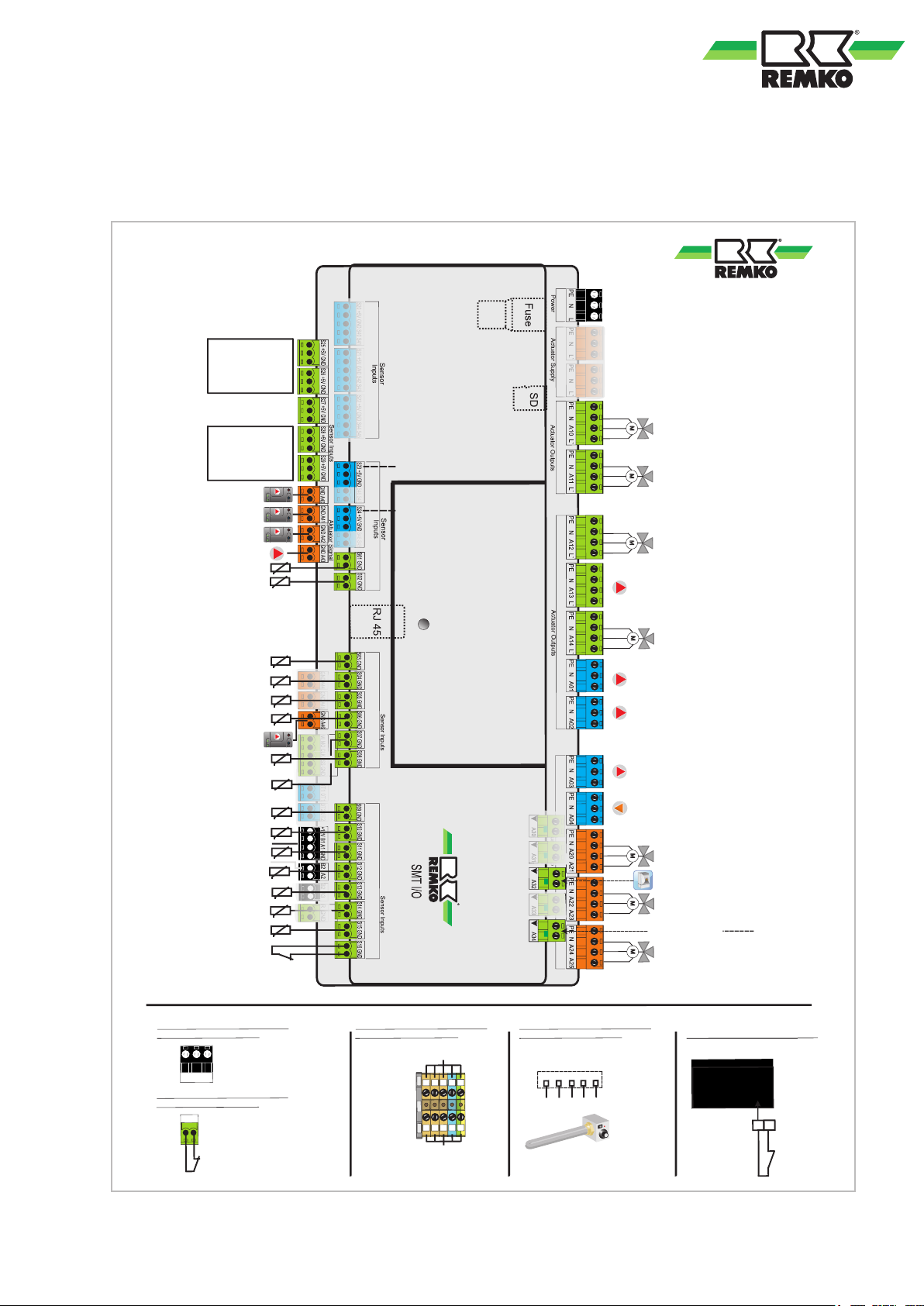
2.5 Electrical configuration - I/O module
Pin assignment for I/O module heat pump WSP
Carel circuit board in the heat pump
Optional pressure switch brine circuit
DI7
GND
PE N L
Connection: 230V/1~/N/PE
(1st)
S16 GND
(2nd)
Power utility contact S16 / Closed = enabled
Contact: Potential-free!
Connection provided by the customer
from the sub-distribution unit
L3
L3
L1
L1
L2
L2
N
N
PE
PE
L1
L2
L3
N
Pe
1 2 3 4 Pe
Plug on the heating coil
Connection: 400V/3~/N/PE
Connection: 400V/3~/N/PE
assigned!
Connection provided by the customer
from the sub-distribution unit
Connection provided by the customer
from the sub-distribution unit
Connection provided by the customer
from the sub-distribution unit
stuptuO rotautcA
KNX - TP
RC
stup
tuO eerF laitnetoP
Power utility contact
closed = enabled
Power supply
I/O module
Potential-free
S0 PV feed-in
(min. 500 lmp./kWh)
S0 PV yield
(min. 500 lmp./kWh)
S0 household meter
(min. 500 lmp./kWh)
S0 HP electricity meter
(min. 500 lmp./kWh)
S29
S28
S26
S25
External probe
S10
S16
Changeover valve
Drinking water
M
A10
Pump unmixed circulation 230V
optional
A03
Circulation pump (230V)
A04
M
Closed
Open
A20/21
NOTE: without power utility connection,
a jumper must be installed
Hot water storage tank
S08
2nd mixed circuit RF
S14
S12
1st mixed circuit INL
S11
1st mixed circuit RF
Storage tank, centre
S09
Acquisition of the stored energy
2nd mixed circuit
20-10V pump
A46
S06
2nd mixed circuit INL
S05
Circulation pump HW
S04
RL Solar WMZ
VL Solar WMZ
S03
S02
Storage tank, bottom
Solar
S01
Solar / collector
1st mixed circuit
0-10V pump
A41
M
Changeover valve
2nd Heat generator
A11
M
Closed
Open
A24/25
Unmixed circuit
0-10V pump
A42
Solar
0-10V pump
A40
Pump 1 mixed circulation 230V
optional
A02
Pump 2 mixed circulation 230V
optional
A13
Pump Solar (230V) optional
A01
Enable 2nd Heat generator
M
Closed
Open
A14
S07
Brine temperature inlet
(2nd)
(1st)
Dyn. hygiene function
S27
Flow probe
BUS 1 communication
BM
BUS 2 communication
BM
S13
INL probe HP
S15
RF probe HP
M
Changeover valve
REMKO cooling module
A12
Changeover valve, cooling
Single room controller
Closed
Open
Bypass mixer HP
A22/23
A34
General alarm signal
Pumpe internal PWM
A43
S23
Ultrasonic flow rate meter Solar
S24
Ultrasonic flow rate meter HP
A32
M
2nd mixed circuit
(Mixing valve)
1st mixed circuit
(Mixing valve)
Use wire gauge corresponding with the connection cable supplied!
Lay load lines separately to measuring lines!
13
Page 14
REMKO series WSP
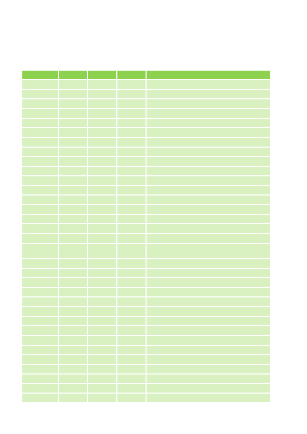
2.6 Terminal assignment / legend
Terminal configuration
Designation Input Output Signal Description
PW X Power supply I/O 230V
PP1 X Power supply primary pump IM
S01 X Solar probe collector PT 1000
S02 X Solar probe storage tank bottom PT 1000
S03 X Solar probe INL HM Solar PT 1000
S04 X Solar probe RF HM Solar PT 1000
S05 X Probe circulation PT 1000 RF Temp./Pulse encoder
S06 X Probe INL 2nd mixed circuit PT 1000
S07 X Brine inlet temperature PT 1000
S08 X Probe drinking water tank top PT 1000
S09 X Probe buffer storage tank middle PT 1000
S10 X External probe PT 1000
S11 X Probe RF 1st mixed circuit PT 1000
S12 X Probe INL 1st mixed circuit PT 1000
S13 X Probe INL heat pump PT 1000
S14 X Probe RF 2nd mixed circuit PT 1000
S15 X Probe RF heat pump PT 1000
S16 X
S20 X Not connected
S21 X Not connected
S22 X Not connected
S23 X Ultrasonic flow rate meter Solar, pulse rate
S24 X Ultrasonic flow rate meter HP, impulse rate
Power utility contact (NC) / dewpoint monitoring
external (open = locked, closed = enabled)
S25 X HP electricity meter S0
S26 X Household electricity S0
S27 X Flow probe hot water
S28 X PV yield electricity meter S0
S29 X PV in-feed electricity meter S0
A01 X Solar pump unregulated (230V)
A02 X Pump 1st mixed circuit (230V) switched
A03 X Pump unmixed Circuit (230V) switched
A04 X Circulation pump (230V) switched
A10 X Changeover valve, hot water
14
Page 15
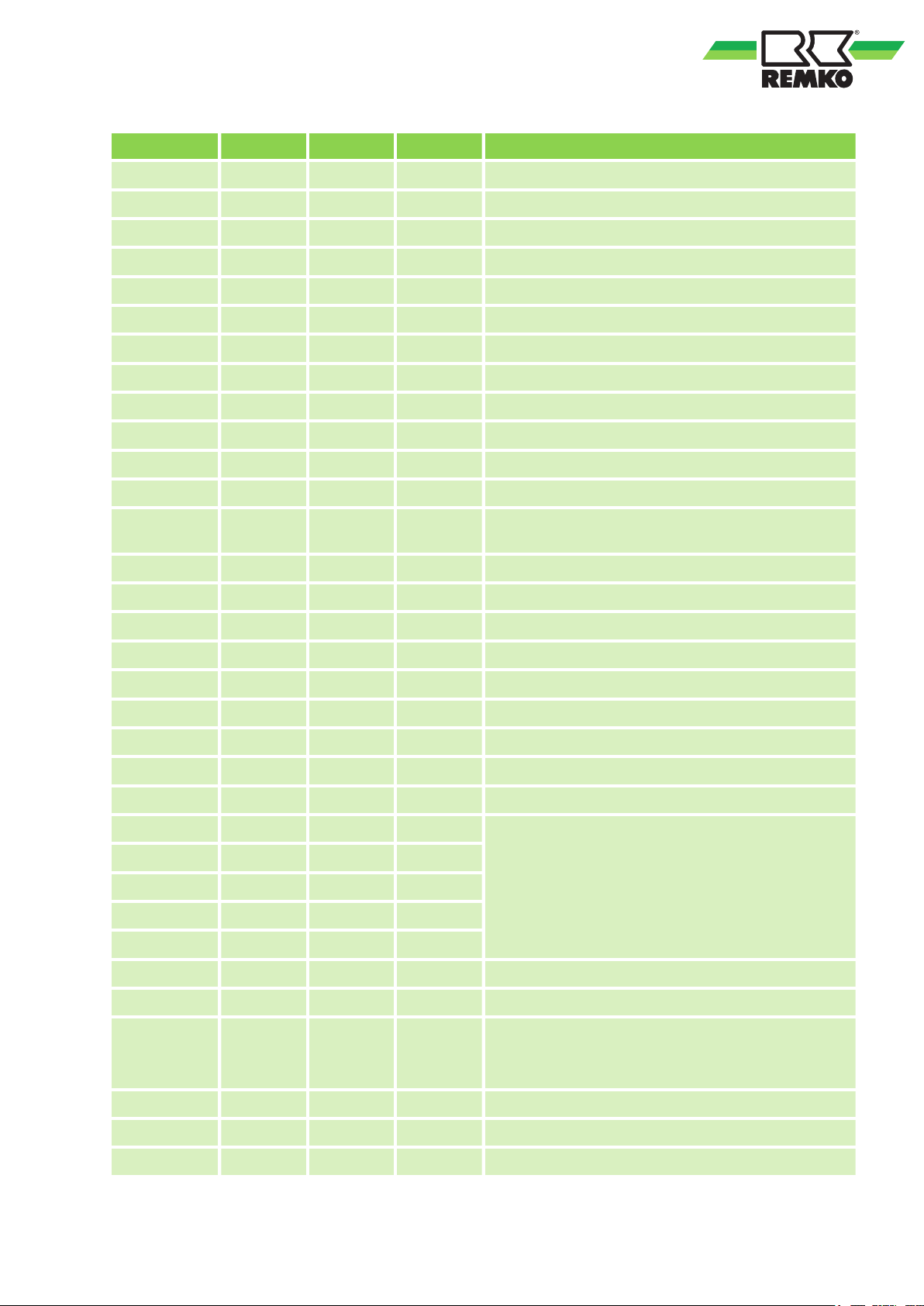
Designation Input Output Signal Description
A11 X Changeover valve 2nd WE (230V)
A12 X REMKO cooling module changeover valve (230V)
A13 X Pump 2nd mixed circuit (230 V) switched
A14 X Changeover valve cool./single room contr. (230V)
A20 X 1st mixing circuit mixing valve “Open” (230V)
A21 X 1st mixing circuit mixing valve “Closed” (230V)
A22 X Bypass mixing valve “Open” (230V)
A23 X Bypass mixing valve “Closed” (230V)
A24 X 2nd mixing circuit mixing valve “Open” (230V)
A25 X 2nd mixing circuit mixing valve “Closed” (230V)
A30 X Not connected
A31 X Not connected
A32 X
A33 X Not connected
A34 X General alarm signal external (potential-free)
A40 X Speed setting solar pump PWM
A41 X Speed specification, 1st mixed circuit (0-10V)
A42 X Speed specification unmixed Circuit (0-10V)
A43 X PWM (pump internal)
A44 X Not connected
A45 X Not connected
A46 X Speed specification, 2nd mixed circuit (0-10V)
MI
MO
CLK
nSS
Enable 2nd WE booster heating or boiler
(potential-free)
Not connected
GND
OT 1 (2x) Not connected
OT 2 (2x) Not connected
B1, A1
+12 V
olt,
GND
B2 / A2 Bus 2 communication
B3 / A2 Not connected
R RC coding resistance
15
Bus 1 communication
Page 16
A
3
2
D
5
4
1
C
B
REMKO series WSP
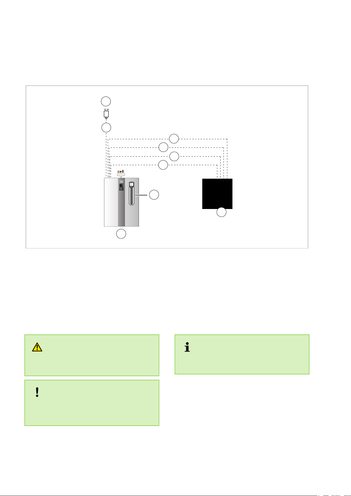
3 Electrical wiring WSP
3.1 Overview of electrical connecting lines
Fig. 4: Overview of electrical connection WSP
A: Heat pump
B: Sub-distribution (provided by the customer)
C: Electrical heating coil
D: External probe
1: Power supply heat pump, 400V/3~/50Hz,
e.g. 5 x 2.5 mm
Fuse WSP 80/110/140 = 3 x 16A
Fuse WSP 180 = 3 x 20A
WARNING!
The configuration of the core cross sections can
only
be defined by an installation specialist!
2
NOTICE!
For an existing block the heat pump by the
utility (utility switching) must be used the control
contact S 16 of the Smart-Control.
2:
Power supply, auxiliary heating, mm
400V/3~/50Hz, 16A, e.g. 5 x 2.5
3: Power supply, Smart Control controller
230V/1~/50Hz, 10A, e.g. 5 x 1.5 mm
4: Potential-free power utility signal for
Smart Control S16, e.g. 2 x 1.0 mm
5:
Sensor cable on external probe, e.g. 2 x 1.0 mm
All connections to the heat pump are made
from above!
2
2
2
2
16
Page 17
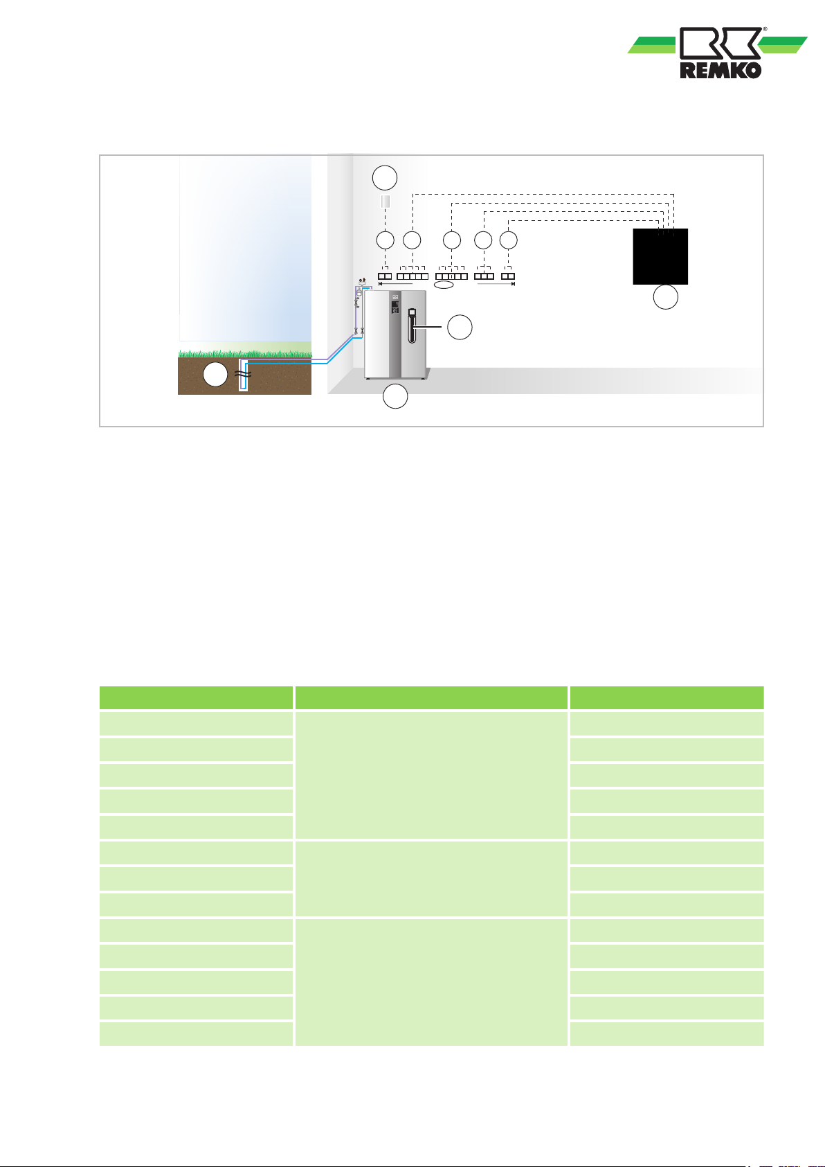
3.2 Overview of terminal assignment
S10 GND
L1 N Pe
L1 L2 L3 N PeL1 L2 L3 N Pe
S16 GND
B
A
C
D
2
3 4
1 5
a
E
Fig. 5: Terminal configuration WSP
A: Heat pump
B: Sub-distribution (provided by the customer)
C: Electrical heating coil
D: External probe
E: Heat source
a: Terminals in unit
1:
Sensor cable on external probe, e.g. 2 x 1.0 mm
2: Power supply, auxiliary heating,
400V / 3~ / 50Hz, 16A, e.g. 5 x 2.5 mm
2
3: Power supply heat pump, 400V/3~/50Hz,
e.g. 5 x 2.5 mm
2
Fuse WSP 80/110/140 = 3 x 16A
Fuse WSP 180 = 3 x 20A
4: Power supply, controller (I/O module)
2
400V/3~/50Hz, e.g. 3 x 1.5 mm
5: Smart Control signal cable
2
(potential-free power utility signal),
e.g. 2 x 1.0 mm
2
Electrical connections between distribution and heat pump
Distribution - terminal Description Heat pump - terminal
L1
L1
L2 L2
L3 L3
Power supply, heat pump 400V/ 3~/50Hz
N N
Pe Pe
L
N N
Power supply, Smart-Control 230V/1~/
50Hz
L
Pe Pe
L1
L2 L2
Power supply, Smart-Serv 400V/3~/ 50Hz
L3 L3
N N
9kW
Pe Pe
L1
17
Page 18
L3
-X1
Spannungsvers. 400V
Verdichter - Bauseits
N
-X2.2
N, PE / E-Heizer
-> EHZ - ST2
PE
L2 L1 N PE
PE
A2
-K1
Freigabe Verdichter
-> µPC / NO1
M
3
T3
T2
T1
PE
-K1
Spannung 400V
Verdichter
DI2
-PR1
Phasenüberwachung
-> µPC - DI2
GND
X1.1
Klemmblock X
X1.2
X1.3
X1.4
X1.5
K1
PR1
X2.1
X2.2
X2.3
L3
L2
L1
N
PE
A2
14/NO
6T3
4T2
2T1
1412
11
1
23
45
6
7
L3
L2
L1
N
PE
A1
13/NO
5L3
3L2
1L1
L2
L1 L3
2 3
4 5
6
7
-X
Klemmblock
1
M
PE
L
N
-X2.1
Pumpe 230V
Solekreis
G0
-X2.1
Solepumpe 230V
-> µPC - G0/G
G
1
M
PE
L
N
-X2.2
Pumpe 230V / max. 1A
Solekreis extern
NO6
-X2.2
Freigabe Ext. Solep.
-> µPC - NO6
6
-X2.3
Brücke / Öffner
Ext. Sicherheitseinrichtung
DI7
-X2.3
Öffner Kontakt
-> µPC - DI7
7
DIC1
0 1 2 3 4 5 6 7 8 9 10 11
1/6
WSP
0 1 2 3 4 5 6 7 8 9 10 11
4/10/2018
Projekt Titel:
Terminal block X
Power supply 400V
Voltage 400V
Phase monitoring
Brine pump 230V
N, PE / E-heater
Open contact
Terminal block
Enable Ext. Brine p.
Pump 230V / max. 1A
Pump 230V
Jumper / NC switch
Enable compressor
Compressor - provided
by the customer
Compressor
-> μPC / DI2
-> μPC - G0/G
-> EHZ - ST2
-> μPC / DI7
-> μPC / NO6
Brine circuit, external
Brine circuit
Ext. safety device
-> μPC / NO1
Project title: WSP
4/10/2018
REMKO series WSP
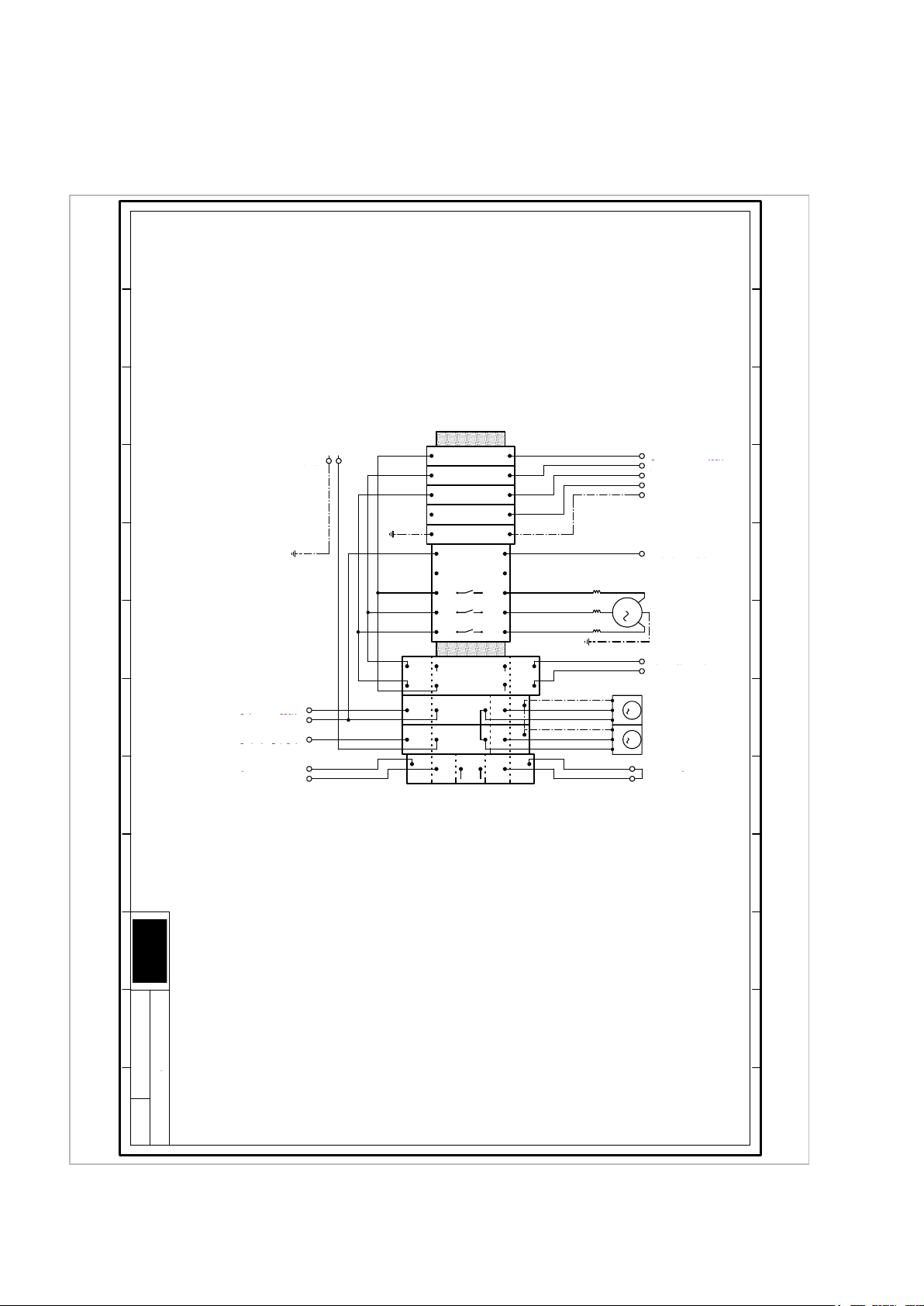
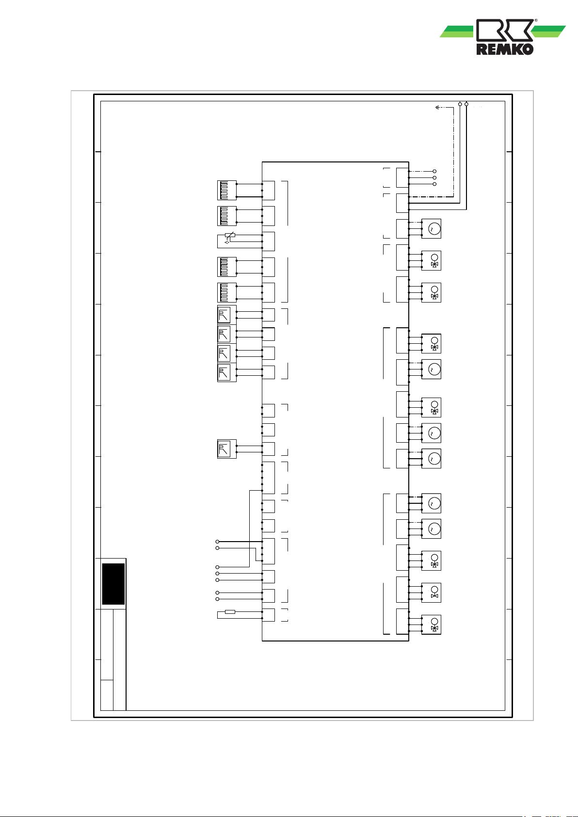
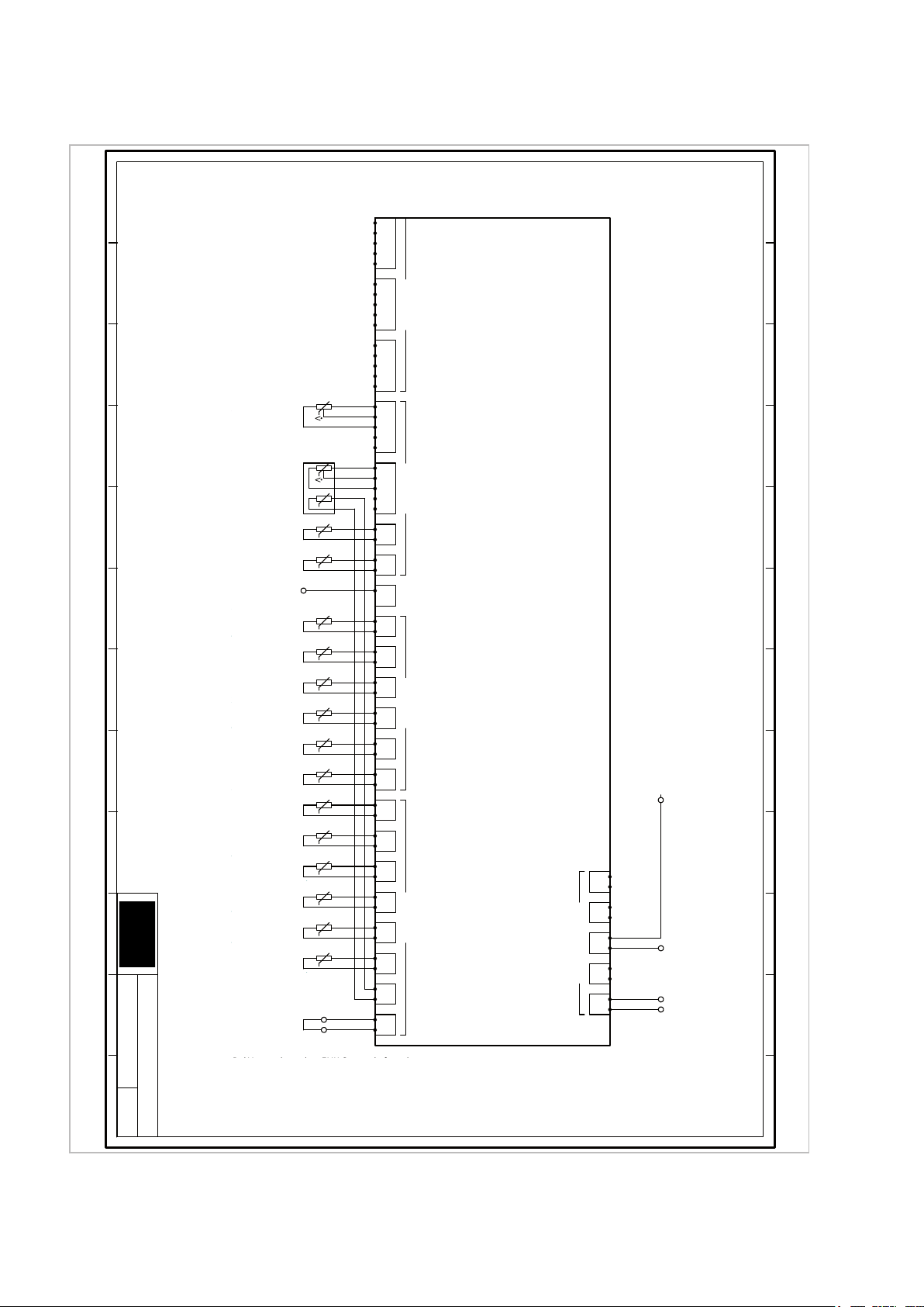
4 Circuit diagrams
18
Page 19
G0
-Pout1
Spannungsversorgung 230V
-> µPC - J1
G
PE
PE
-Pin
Spannungsversorgung 230V
SMT I/O - Bauseits
N L
S0
Imp/kWh
+
-
-S25
Stromzähler S0
Wärmepumpe
S0
Imp/kWh
+
-
-S26
Stromzähler S0
Haushalt
1
M
PE
N
L
-Pout2
Versorgung 230V
Interne Pumpe A43
13 1
4
-S27
Volumenstrom, Imp.
Warmwasser
M
N
SP
DP
-A10
Umschaltventil 230V
Warmwasserbereitung
S0
Imp/kWh
+
-
-S28
Stromzähler S0
PV Ertrag
S0
Imp/kWh
+
-
-S29
Stromzähler S0
PV Einspeisung
M
N
SP
DP
-A11
Umschaltventil 230V
2. Wärmeerzeuger
U
t
-
+
-A40
Signal PWM
Solarkreis
U
t
-
+
-A41
Signal 0-10V / PWM
1. gem. Kreis
M
N
SP
DP
-A12
2x Umschaltventil 230V
Modul passiv Kühlen
U
t
-
+
-A42
Signal 0-10V / PWM
ungem. Kreis
1
M
PE
N
L
-A13
Pumpe 230V
2. gem. Kreis
U
t
-
+
-A43
Signal PWM
Interne Pumpe
Power Actuator Output Actuator Output Actuator OutputActuator Supply
Sensor Inputs Actuator Signal Actuator Signal SPI OT Interfaces Bus Interfaces Rc
Systemregler SMT I/O
PE
N
L
PE
N
L
PE
N
L
PE
N
A10
L
PE
N
A11
L
PE
N
A12
L
PE
N
A13
L
PE
N
A14
L
PE
N
A01
PE
N
A02
PE
N
A03
PE
N
A04
PE
N
A20
A21
PE
N
A22
A23
PE
N
A24
A25
S25
+5V
GND
S26
+5V
GND
S27
+5V
GND
S28
+5V
GND
S29
+5V
GND
GND
A40
GND
A41
GND
A42
GND
A43
GND
A44
GND
A45
GND
A46
MI
MO
CLK
nSS
GND
OT1
OT1
OT2
OT2
+12V
B1
A1
GND
B2
A2
B3
A3
R
GND
-SMT_I/O_UNTEN
Systemregler
M
N
SP
DP
-A14
Umschaltventil 230V
Separater Kühlkreis
1
M
PE
N
L
-A01
Pumpe 230V
Solarkreis
U
t
-
+
-A46
Signal 0-10V / PWM
2. gem. Kreis
1
M
PE
N
L
-A02
Pumpe 230V
1. gem. Kreis
1
M
PE
N
L
-A03
Pumpe 230V
ungem. Kreis
1
M
PE
N
L
-A04
Pumpe 230V
Trinkwasser Zirkulation
+12V
-12V
Spannungsvers.
-> SMT Touch
GND
M
N
Auf
Zu
-A20/A21
Mischventil 230V
1. gem. Kreis
GND
-B2/A2
Kommunikation
-> µPC - J6
- +
M
N
Auf
Zu
-A22/A23
Ventil 230V
Bypass
B
-B3/A3
Kommunikation
-> Raumsensor - B/A
A
1
2
-RC
Kodierwiderstand
Geräteabhängig
M
N
Auf
Zu
-A24/A25
Mischventil 230V
2. gem. Kreis
Kodierwiderstände:
WSP 80 -> 200 Ohm
WSP 110 -> 240 Ohm
WSP 140 -> 300 Ohm
WSP 180 -> 360 Ohm
WSP 80 -> 200 Ohm
WSP 110 -> 240 Ohm
WSP 140 -> 300 Ohm
WSP 180 -> 360 Ohm
0 1 2 3 4 5 6 7 8 9 10 11
2/6
WSP
0
1 2 3 4 5 6 7 8 9 10 11
4/10/2018
Projekt Titel:
Signal 0-10V / PWM
Signal PWM
Signal 0-10V / PWM
Signal 0-10V / PWM
Signal PWM
Electricity meter S0
Electricity meter S0
Medium ow rate, Imp.
Electricity meter S0
Power supply 230V
Changeover valve 230V
Changeover valve 230V
Pump 230V
Changeover valve 230V
Pump 230V
Pump 230V
Mixed valve 230V
Valve 230V
Mixed valve 230V
Pump 230V
Pump 230V
2x changeover valves 230V
Electricity meter S0
Power supply 230V
Power supply 230V
Power supply
Communication
Communication
System controller
-SMT_I/O_BOTTOM
Coding resistor
Coding resistances:
2nd mixed circuit
Internal pump
Unmixed circuit
1st mixed circuit
Solar circuit
PV feed-in
PV yield
Hot water
Household
Internal pump A43
Hot water preparation
2nd Heat generator
2nd mixed circuit
Separate cooling circuit
Solar circuit
1st mixed circuit
1st mixed circuit
Bypass
2nd mixed circuit
Unmixed circuit
Drinking water circulation
Passive cooling module
Heat pump
SMT I/O - Provided
by the customer
-> μPC / J1
-> SMT Touch
-> μPC / J6
-> Space probe - B/A
Device-dependent
Project title: WSP
4/10/2018
System controller SMT I/O
Open
Closed
Open
Closed
Open
Closed
19
Page 20
13 1
4
-S23
Volumenstrom, Imp.
Solarkreis
3 1 4 2 5
-S15/S24
PT1000 / Vol. Imp.
RL / Vol. Wärmep.
1
2
-S01
PT1000
Kollektorfühler
1
2
-S02
PT1000
Speicherfühler, Solar
RJ45
-RJ45
Kommunikation
-> SMT Touch
1
2
-S03
PT1000
Vorlauf, Solar
1
2
-S04
PT1000
Rücklauf, Solar
1
2
-S05
PT1000 / Impuls
Zirkulation
1
2
-S06
PT1000
Vorlauf, 2. gem. Kreis
1
2
-S07
PT1000
Eintritt, Solekreis
1
2
-S08
PT1000
Warmwasserspeicher
G0
-A32
Spannung 230V
-> µPC - G0
1
2
-S09
PT1000
Pufferspeicher
1
2
-S10
PT1000
Außentemperatur
1
2
-S11
PT1000
Rücklauf, 1. gem. Kreis
1
2
-S12
PT1000
Vorlauf, 1. gem. Kreis
1
2
-S13
PT1000
Vorlauf, Wärmepumpe
Potential Free Outputs
Sensor InputsSensor InputsSensor InputsSensor Inputs
Systemregler SMT I/O
In
A30
In
A31
In
A32
In
A33
In
A34
S20
+5V
GND
S40
S41
S21
+5V
GND
S42
S43
S22
+5V
GND
S44
S45
S23
+5V
GND
S46
S47
S24
+5V
GND
S48
S49
S01
GND
S02
GND
RJ45
S03
GND
S04
GND
S05
GND
S06
GND
S07
GND
S08
GND
S09
GND
S10
GND
S11
GND
S12
GND
S13
GND
S14
GND
S15
GND
S16
GND
-SMT_I/O_OBEN
Systemregler
L
-A32
Freigabe E-Heizer
-> EHZ - ST2
1
2
-S14
PT1000
Rücklauf, 2. gem. Kreis
In
-A34
Potentialfreier Kontakt
Sammelstörmeldung
A34
S16
-S16
Brücke / Öffner-K.
EVU Sperre
GND
Bei Verwendung einer EVU Sperre darf nur der
Verdichter Spannungslos geschaltet werden!Verdichter Spannungslos geschaltet werden!
0 1 2 3 4 5 6 7 8 9 10 11
3/6
WSP
0
1 2 3 4 5 6 7 8 9 10 11
4/10/2018
Projekt Titel:
Medium ow rate, Imp.
PT1000 / Vol. Imp.
PT1000
PT1000
PT1000
PT1000 / Impulse
PT1000
PT1000
PT1000
PT1000
PT1000
Jumper / NC terminal
PT1000
PT1000
PT1000
Enable E-heater
Voltage 230V
Potential-free contact
PT1000
Communication
PT1000
Solar circuit
RF / Vol. Heat Pump
Collector probe
Inlet, Solar
Return ow, Solar
Circulation
Inlet, 2nd mixed circuit
Hot water storage tank
Inlet, brine circuit
Buer tank
Outside temperature
Power utility block
Return ow, 1st mixed circuit
Inlet, 1st mixed circuit
Inlet, heat pump
-> EHZ - ST2
-> μPC / G0
General alarm signal
Return ow, 2nd mixed circuit
-> SMT Touch
Storage tank probe, Solar
Project title: WSP
4/10/2018
System controller SMT I/O
When using a power utility block, only power
to compressor may be switched!
System controller
-SMT_I/O_TOP
REMKO series WSP
20
Page 21
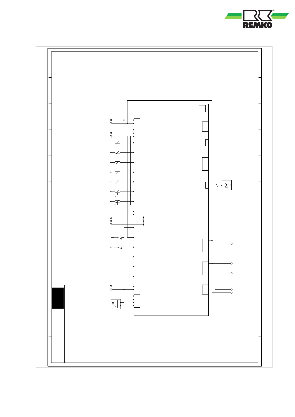
N
-J1
Spannungsv. 230V
-> SMT I/O - Pout1
L 11
-DI2
Öffner Kontakt
-> Phasenüberw. PR1
14
1
2
-B1
NTC
Wasser Eintritt
1
2
-B2
NTC
Wasser Austritt
1
2
-B3
NTC
Sole Austritt
1
2
-B4
NTC
Sauggas
1
2
-B5
NTC-HT
Heißgas
S
J11
-J11
Steuersignal
Expansionsventil
1 3
2
-B6
RAZ 0-5V
Niederdruck
1 3
2
-B7
RAZ 0-5V
Hochdruck
GND
-J6
Kommunikation
-> SMT I/O - B2/A2
A2 B2
V
1
2
-DI1
Öffner-Kontakt
Durchflusswächter
J7
J8
J9
J10
J11
J12 J13 J14
J1 J2 J3
J6
J4 J5
Kätekreis Regler µPC
1 2 34 12 3 456
pLAN
R-/TR+/T+
GND
Vout
R-/TR+/T+
GND
C1
NO1
NO2
NO3
C2
NO4
NO5
NO6
NO7
C3
NC7
G
G0
+Vdc
GND
+5VR
B1
B2
B3
B4
B5
B6
B7
GND
+Vdc
GND
+
-
DI1
DI2
DI3
DI4
DI5
DI6
DI7
DIC1
GND
Y1
Y2
Y3
-µPC
Kältekreis Regler
A2
-NO1
Freigabe Verdichter
-> Schütz K1
P
1
2
-DI3
Öffner-Kontakt
Hochdruckschalter
In
-G0
Spannung 230V
-> SMT I/O - A32
4
-NO6
Freigabe Ext. Solep.
-> Klemmblock X2.2
6
-DI7
Öffner Kontakt
-> Klemmblock X2.3
3
-G/G0
Solepumpe 230V
-> Klemmblock X2.1
7
2
U
t
-
+
-Y3
Signal PWM
Pumpe Solekreis
6
0 1 2 3 4 5 6 7 8 9 10 11
4/6
WSP
0
1 2 3 4 5 6 7 8 9 10 11
4/20/2018
Projekt Titel:
Power supply 230V
NTC
NTC
NTC
NTC
Control signal
Enable compressor
Voltage 230V
Enable Ext. Brine p.
Brine pump 230V
NTC-HT
RAZ 0-5V
RAZ 0-5V
Communication
Open contact
Open contact
Open contact
Signal PWM
Open contact
-> SMT I/O - Pout1
Water inlet
Water outlet
Brine outlet
Suction gas
Expansion valve
-> contactor K1
-> SMT I/O - A32
-> Terminal block X2.2
-> Terminal block X2.1
Hot gas
Low pressure
High pressure
-> SMT I/O - B2/A2
Flow rate monitor
High pressure switch
-> Terminal block X2.3
Pump, brine circuit
-> Phase monitoring PR1
Project title: WSP
4/20/2018
Cold circuit controller μPC
Cooling cycle controller
-μPC
21
Page 22
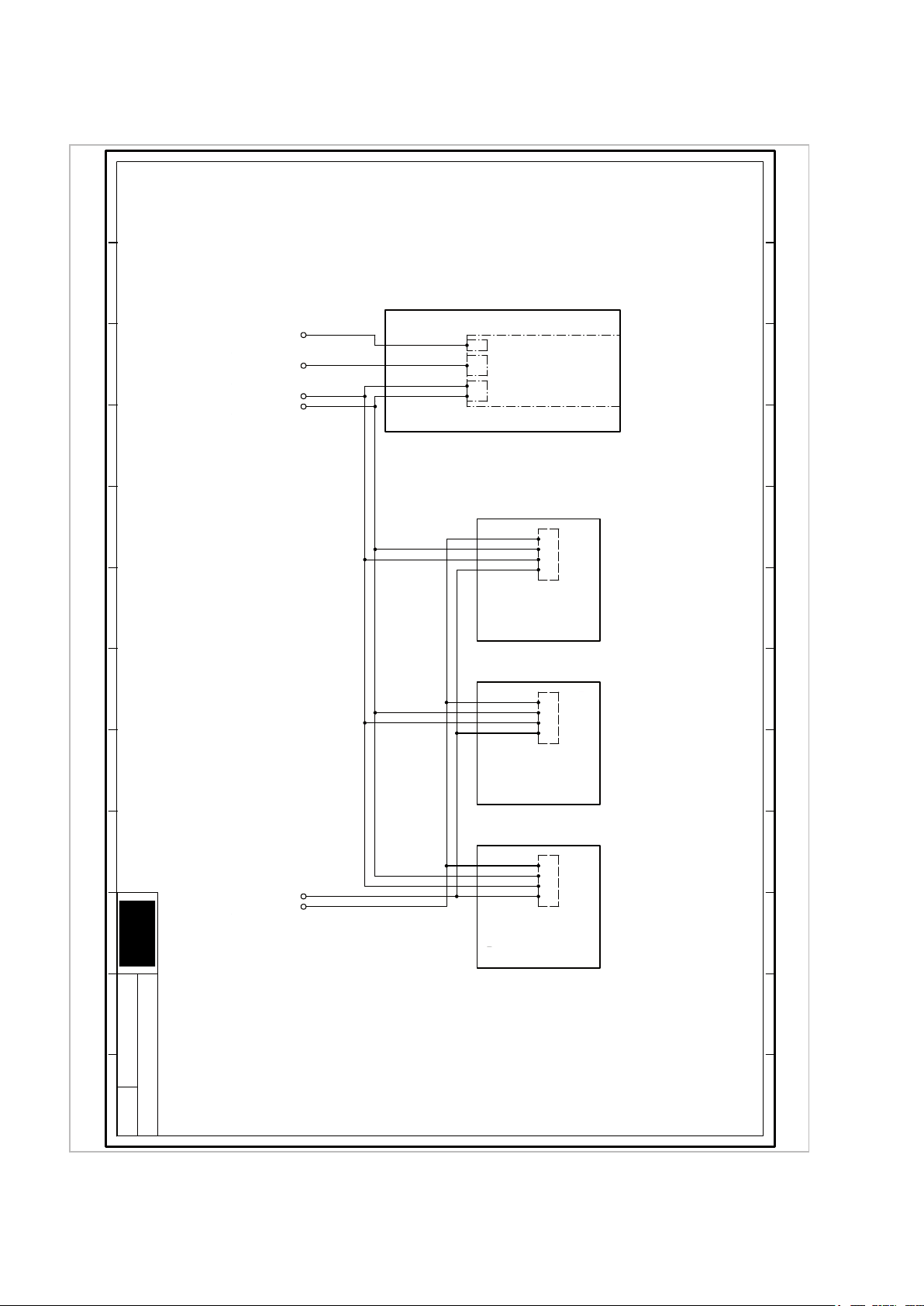
USB
-USB
Kommunikation
-> LAN - / WLAN Adapter
Smart-Control Touch
USB
RJ45
GND
+12V
-SMT_Touch
Bedienteil
RJ45
-RJ45
Kommunikation
-> SMT I/O - RJ45
GND
-12V
Spannungsvers.
-> SMT I/O - 12V
+12V
Raumsensor
A
V+
VB
-RS1
Raumsensor
ungem. Kreis
Raumsensor
A
V+
VB
-RS2
Raumsensor
1. gem. Kreis
Raumsensor
A
V+
VB
-RS3
Raumsensor
2. gem. Kreis
B3
-B/A
Kommunikation
-> SMT I/O - B3/A3
A3
Jeder Raumsensor benötigt eine eindeutige Geräteadresse!
-> Siehe Bedienunsanleitung des Raumsensors. -> Siehe Bedienunsanleitung des Raumsensors.
0 1 2 3 4 5 6 7 8 9 10 11
5/6
WSP
0
1 2 3 4 5 6 7 8 9 10 11
4/10/2018
Projekt Titel:
Project title: WSP
4/10/2018
Smart Control Touch
Space probe
Space probe
Space probe
Each space probe requires a unique device address!
-> See the operating instructions for the space probe.
Communication
Communication
Space probe Space probe Space probe
Control element
Communication
Power supply
-> SMT I/O - B3/A3
-> SMT I/O - RJ45
Unmixed circuit 1st mixed circuit 2nd mixed circuit
-> LAN - / WLAN adapter
-> SMT I/O - 12V
REMKO series WSP
22
Page 23
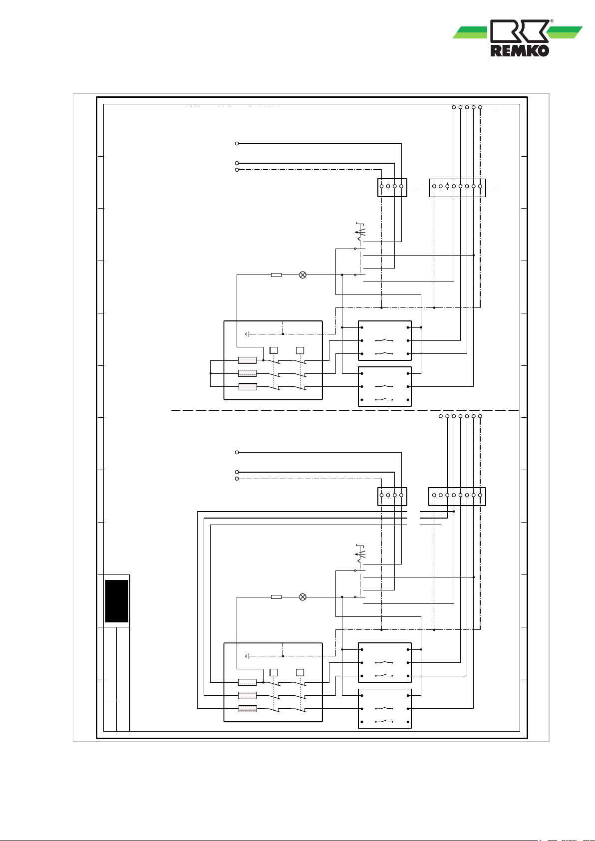
PE
-EHZ
Spannungsvers. 400V
Bauseits
L1L2L3
N
A32
-ST2
Freigabe E-Heizer
-> SMT I/O - A32
N
-ST2
N, PE E-Heizer
-> X2.2
PE
PE
-ST1
Stecker Spannung 400V
Elektro Heizstab
123456PE
1
-ST2
Stecker Steuerleitung
Elektro Heizstab
23PE
0 21
L-ST L1 N-ST N-LL
L N
-SN1
X1
X2
-H1
1
2
-R1
K2.1
K2.2
A1
11
21
A1
11
21
A2
14
24
A2
14
24
STB 95°C
30°C - 78°C
-EHZ
Elektro Heizstab
PE
-EHZ
Spannungsvers. 3x230V
Bauseits
LLLNN
N
A32
-ST2
Freigabe E-Heizer
-> SMT I/O - A32
N
-ST2
N, PE E-Heizer
-> X2.2
PE
PE
-ST1
Stecker Spannung 400V
Elektro Heizstab
123456PE
1
-ST2
Stecker Steuerleitung
Elektro Heizstab
23PE
0 21
L-ST L1 N-ST N-LL
L N
-SN1.
X1
X2
-H1.
1
2
-R1.
K2.1
K2.2
A1
11
21
A1
11
21
A2
14
24
A2
14
24
STB 95°C
30°C - 78°C
-EHZ.
Elektro Heizstab
Elektro Heizstab 3x230V
Elektro Heizstab 400V
0 1 2 3 4 5 6 7 8 9 10 11
6/6
WSP
0
1 2 3 4 5 6 7 8 9 10 11
4/10/2018
Projekt Titel:
Project title: WSP
4/10/2018
Electric heating element 400V
Electric heating element 3x230V
Enable E-heater
Enable E-heater
Electric heating element Electric heating element
N, PE E-heater
N, PE E-heater
Plug for control line Plug for control line
Plug voltage 400V Plug voltage 400VPower supply 400V Power supply 3x230V
-> SMT I/O - A32
-> SMT I/O - A32
-> X2.2
-> X2.2
Electric heating element Electric heating element
Electric heating element Electric heating elementProvided by the customer Provided by the customer
23
Page 24

REMKO series WSP
Legend for the circuit diagrams
E-heater: Electric heating element
EHZ: Electric heating element
Power utility: Electrical power company
Ext.: External
mix.: mixed
Imp.: Impulse
PV: Photovoltaic
PWM: Pulse width modulation
RF: Return flow
Brine p.: Brine pump
unmixed: unmixed
Vol.: Medium flow rate
24
Page 25

5 Index
C
Circuit diagrams ........................ 18
Circuit diagrams, legend .................. 24
Collector probe ......................... 1
Connection diagram I/O module ............ 13
Connection of the contact probe ............ 11
Connection of the external probe ........... 12
Connection of the temperature probes ....... 11
Contact probe, connection .................11
1
D
Disposal of equipment .....................6
E
Electrical connecting lines, overview ......... 16
Electrical connection
Heat pump ........................... 8
Electrical connections between distribution and
heat pump .............................17
Environmental protection ...................6
External probe, connection ................ 12
G
General notes ........................... 7
I
I/O module, connection diagram ............ 13
Immersion probe ........................ 11
Industrial hot water probe ................. 11
Intended use ............................ 5
L
Legend for circuit diagrams ................ 24
Legend terminal assignment ............... 14
N
Notes, general ...........................7
O
Overview of electrical connecting lines ....... 16
Overview of terminal assignment ........... 17
R
Residual current devices ................... 8
S
Safety
Dangers of failure to observe the safety
notes ............................... 4
General ............................. 4
Identification of notes ................... 4
Note for inspection work .................5
Note for installation work ................ 5
Note for maintenance work .............. 5
Personnel qualifications ................. 4
Safety notes for the operator ............. 5
Safety-conscious working ................4
Unauthorised modification ...............5
Unauthorised replacement part manufacture . 5
Smart Control ........................... 7
System layout ........................... 7
T
Tank probe ............................ 11
Temperature probes, connection ............ 11
Terminal assignment legend ............... 14
Terminal assignment, overview ............. 17
W
Warranty ............................... 5
25
Page 26

REMKO series WSP
26
Page 27

Page 28

Consulting
Thanks to intensive training,
our consultants are always
completely up-to-date in terms
of technical knowledge. This has
given us the reputation of being
more than just an excellent,
reliable supplier:
REMKO, a partner
helping you find solutions to
your problems.
Distribution
REMKO offers not just a well
established sales network both
nationally and internationally, but
also has exceptionally highlyqualified sales specialists.
REMKO field staff are more than
just sales representatives: above
all, they must act as advisers to
our customers in air conditioning
and heating technology.
SFlbCustomer Service
Our equipment operates
precisely and reliably. However,
in the event of a fault, REMKO
customer service is quickly at
the scene. Our comprehensive
network of experienced dealers
always guarantees quick and
reliable service.
REMKO INTERNATIONAL
… and also right in your neighbourhood!
Make use of our experience and advice
We reserve the right to make technical changes, and provide no guarantee as to the accuracy of this data!
REMKO GmbH & Co. KG
Air conditioning and heating technology
Im Seelenkamp 12 D-32791 Lage
Postfach 1827 D-32777 Lage
Telephone +49 5232 6 06-0
Telefax +49 5232 606-2 60
E-mail [email protected]
Website www.remko.de
 Loading...