

Page 1
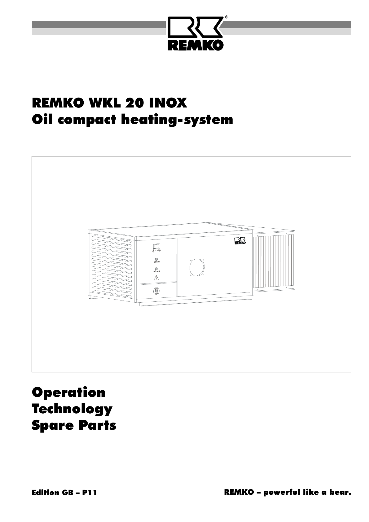
REMKO WKL 20 INOX
Oil compact heating-system
Operation
Technology
Spare Parts
Edition GB – P11
REMKO – powerful like a bear.
Page 2

Page 3
Operating Instructions
Read these instructions carefully before setting up/operating the unit!
Our guarantee becomes null and void if the unit is used, set up or maintained improperly,
or if modifications are made to the supplied unit without our prior consent.
Subject to alterations!
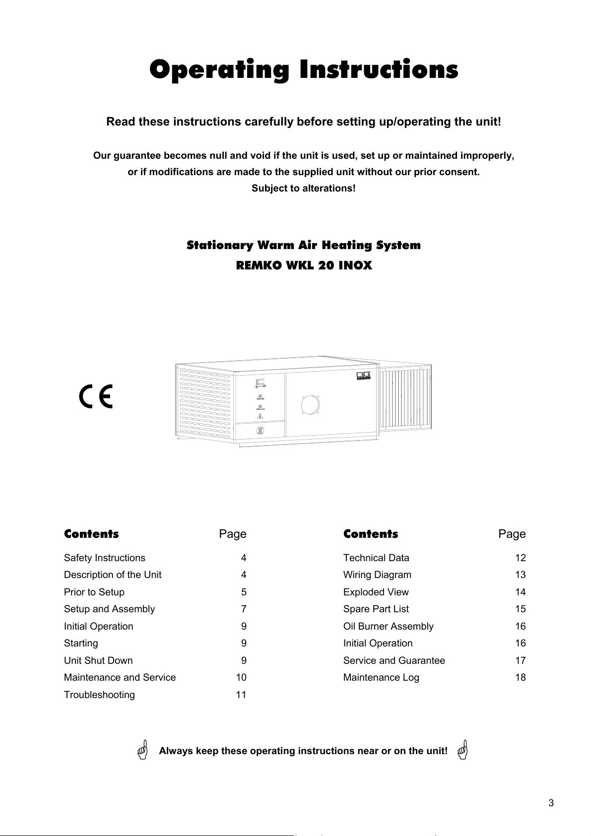
Stationary Warm Air Heating System
REMKO WKL 20 INOX
Contents Page
Safety Instructions 4
Description of the Unit 4
Prior to Setup 5
Setup and Assembly 7
Initial Operation 9
Starting 9
Unit Shut Down 9
Maintenance and Service 10
Troubleshooting 11
Always keep these operating instructions near or on the unit!
Contents Page
Technical Data 12
Wiring Diagram 13
Exploded View 14
Spare Part List 15
Oil Burner Assembly 16
Initial Operation 16
Service and Guarantee 17
Maintenance Log 18
3
Page 4
Safety Instructions
Make sure to observe relevant local building and fire
protection codes and abide by professional association
regulations when the units are in operation!
Description of the Unit
The units (automatic heaters) have been designed for
universal, fully-automatic and smooth operation. They
are fired directly with heating oil or diesel.
Before performing any maintenance or repair work,
make sure to unplug the units from the power supply!
Remove fuses or switch off the customer-supplied
main switch.
It is not sufficient to switch off the units with the
operating switch!
The units may only be operated by persons who
have received proper training in their operation.
The units must be installed and operated in such a
way that people are not exposed to radiant heat and
fires cannot occur.
The units may only be installed and operated in
closed rooms where the units have adequate air
supply for combustion.
If this cannot be guaranteed, a separate burner-
driven device that sucks in fresh air from the outside
must be installed.
The units may only be set up on a non-flammable
surface.
The units may only be attached to non-flammable,
sturdy structures or ceilings made from the materials
with sufficient load-bearing capacity.
The units are to be attached with sturdy mounts
which are fixed on the unit.
The units may not be set up or operated in surround-
ings susceptible to fire or explosions.
The units must be set up outside of traffic zones,
e.g. away from cranes.
A safety zone of 1 m is to be maintained around the
units.
The protective air suction grille must always be kept
free of dirt and loose objects.
Never insert foreign objects into the units.
Do not expose the units to a direct stream of water.
Never let water get inside the units.
All of the units’ electrical cords are to be protected
from damage (e.g. caused by animals, etc.).
Do not bypass or block safety mechanisms while
the unit is in operation.
Proper Use
The units have been designed and equipped exclu-
sively for industrial and commercial heating and ventila-
tion purposes.
The manufacturer assumes no liability for damage re-
sulting from non-compliance with manufacturer specifi-
cations and legal requirements, or if modifications are
made to the units.
The units are designed for exclusive use with 1-speed
fan/burner operation.
The units are operated with a separate forced-air oil
burner.
It is essential to connect the units to an exhaust system
approved by the state building authorities.
The units are equipped with a 1-speed radial fan with
drive motor that runs quietly and requires little mainte-
nance as well as attached switching and regulating units.
The units meet the basic safety and health require-
ments found in the relevant EU regulations. They are
safe and easy to operate.
The robust design and clean processing of these high-
quality units ensure a long service life and smooth op-
eration. They can also be assembled quickly, easily and
affordably and are easy to service.
Operating Locations of the Units
The units are direct-fired devices that supply instanta-
neous heat. They are only used for industrial and com-
mercial purposes. There are generally no restrictions as
to where they can be used.
REMKO automatic heaters supply heat or regulate the
temperature of:
Workshops
Warehouses
Exhibition spaces
Trade show spaces
Temporary structures for warehousing
Showrooms
Greenhouses etc.
Operation
After switching on the unit by setting the operating
switch to “Heizen” (heating), the forced-air burner turns
on automatically.
he green “burner“ operating light is illuminated on the
control panel for monitoring purposes. The combustion
chamber with heat-exchanger now heats up until the
target temperature is reached.
After the burner has run for a short time, the temperature
control thermostat “TR” (rated temperature 35 to 40 °C)
automatically switches the air supply fan on. Warm air
is blown out.
The combustion chamber with heat-exchanger is
heated up until the target temperature of the tempera-
ture monitor (TW) is reached.
4
Page 5
If heating mode is controlled via a room thermostat or
other temperature regulating device (operating switch
set to “Heizen” (heating), the units function fully-
automatically based on amount of heat required.
All of the unit functions are performed automatically and
monitored by the integrated temperature control mecha-
nism and the automatic burner relay (part of the forced-
air burner).
After the device is switched off with the operating switch
or the room thermostat, the air supply fan runs for a cer-
tain amount of time to cool the combustion chamber
with heat-exchanger and then switches off. This proc-
ess can be repeated several times.
Never interrupt (except in emergency situations)
the power supply until the cool-down phase is
completely finished. Our guarantee does not cover
damages caused to the unit by overheating.
Monitoring unit operation
If the flame burns irregularly or goes out, the unit is
switched off by the automatic burner relay. The unit
may only be restarted after the automatic burner relay
has been manually released.
The integrated temperature monitor (TW) regulates the
temperature of the units and the air being blown out
during heating operation.
The safety temperature limiter (STB) interrupts opera-
tion of the unit or burner when extreme overheating oc-
curs or if the TW ceases functioning. The STB can only
be manually released after the unit has cooled.
Before releasing the safety temperature limiter
(STB), the possible causes of the malfunction must
be investigated.
Information on the Safety Temperature Limiter (STB)
Prior to Setup
When setting up the units, the relevant regional building
and fire protection codes of the respective region must
be observed.
Selecting the Setup Location
When selecting a location to set up the units, the re-
quirements must be adjusted with respect to:
1. Fire protection and operating hazards.
2. Function.
When the units are used to heat rooms, when it is
necessary to adjust to the amount of pressure in the
room, etc.
3. Operating needs.
Heating requirements, rated air output, need for cir-
culation or outside air, humidity, room temperature,
air distribution, space needs, etc.
4. How the unit is connected to the exhaust system.
Oil fired warm air generators (including those with a
rated heat capacity of more than 50 kW) may generally
be set up outside of heating rooms in compliance with
the German fire ordinance.
For rooms where slightly flammable materials or mix-
tures are processed, stored or produced that could be
dangerous if ignited, exceptions may be made if appro-
priate measures are taken to ensure that the materials
or mixtures cannot catch fire.
The unit must be set up and assembled in such a
way that it is easily accessible for monitoring, re-
pair and maintenance work.
Important Information about Safe Setup
The units may only be set up and operated in rooms
where there is enough air for combustion and the
expelled air is guided to the outside via an exhaust
system.
The device is equipped with a sensor monitoring feature
and is resistant to cool down to temperatures of -20°C;
below -20°C the device switches off; when the tempera-
ture rises above this temperature, it switches on again.
When the sensor or capillary tube is damaged, or when
an excess temperature of approximately 220°C is
reached, the liquid contained in the thermostat is emp-
tied and the device switches off for safety purposes.
The device is no longer operable and must be replaced
If it is necessary to replace the STB, only the original
REMKO part may be used.
Do not bend the capillary tubes near to solder points.
When installing the capillary tubes, be careful not to
damage or bend them too sharply.
The sensors may only be mounted in the mounting
brackets supplied by the manufacturer.
The sensors must always be free from dust and dirt.
Units dependent on air in the room may only be set
up in rooms or buildings from which air is suctioned
out by means of fans (such as ventilation or exhaust
systems) if:
1. Safety mechanisms prevent the units and the air
suctioning system(s) from operating simultane-
ously.
2. The expulsion of exhaust is monitored by special
safety devices.
3. The exhaust produced by the units is expelled by
means of the air suctioning system(s).
4. The design or dimensions of the system ensure
that no dangerous negative pressure can be pro-
duced.
The units must be placed firmly on a suitable, non-
flammable surface outside of traffic zones, for exam-
ple, away from cranes.
5
Page 6
Air Supply for Combustion
The units must be set up and operated in such a
way that people are not exposed to exhaust or radi-
ant heat and fires cannot occur.
The units must be set up in such a way that they do
not cause any hazards or unreasonable annoy-
ances, e.g. tremors, vibrations or noise.
The units must be set up and installed in such a way
that they are easily accessible for monitoring, repair
and maintenance work.
Operating elements which can result in dangerous
operating conditions when used improperly must be
protected from unauthorised operation if they are
generally accessible.
We do not recommend suctioning in outside air di-
rectly with the standard combustion chamber. When
mounting the mixed air flaps (accessories), they
must be attached in the opposite direction. The per-
centage of fresh air supplied may not exceed 30%.
The units may not be set up or operated in rooms or
areas susceptible to fire or explosions.
The units are not suitable exclusively for use
as air supply units.
Heating Rooms
The units only may be operated in closed rooms or
warehouses if they have been equipped with a suitable
room temperature control thermostat (room thermostat).
An adequate supply of air for combustion must be en-
sured by meeting the relevant building requirements.
Excerpts from the German fire ordinance:
For furnaces with a total rated heat output of up to 35
kW that are dependent on the air in the room, evidence
of an adequate air supply for combustion has been pro-
vided if the furnaces are set up in a room that has:
1. A minimum of one door to the outside or a window
that can be opened (rooms with a connection to the
outside) and a room capacity of at least 4 m3 per
kW of total rated hear output or
2. An opening leading to the outside with a cross-
section of at least 150 cm2 or two openings which
are each 75 cm2 or lines to the outside with equiva-
lent cross-sections for air flow.
Combustion air openings and lines may not be closed
or blocked unless the safety mechanisms can ensure
that the furnace can only be operated when the flap is
closed. The required cross-section may not be con-
stricted by the flap or the grille.
As an exception to Paras. 1 and 2, for furnaces de-
pendent on air in the room, evidence of an adequate air
supply for combustion can be provided other ways.
For example by:
A continuous line to the outside with a sufficient
cross-section that is attached to the burner or its lin-
ing. This must be adjusted to the suction capacity of
the burner and the line resistances (including the
protective air suction grille) so that combustion is
assured.
Fuel Supply
Particularly for heating oil lines, make sure that the
cross-section of the lines corresponds to the suction
height, the total line resistance and increased viscosity
at lower temperatures and, if necessary, it is possible to
connect an oil transport device.
The lines must be placed in such a way that they are
easily ventilated and are protected from corrosion and
mechanical damage.
The measured pressure of the suction line should
not exceed -0.3 bar. It may be a maximum of -0.4 bar.
Power Supply
Prior to performing the electrical installation in line with
local requirements, check whether it is possible for even
a temporary power overload to cause an impermissible
undervoltage.
An easily accessible emergency switch must be at-
tached in the setup room, but not close to hazardous
areas.
These units have not been designed for heating
private residences or similar spaces.
Setup on the Ground
The units must be placed firmly on non-flammable sur-
face outside of traffic zones, e.g. away from cranes.
A safety zone of 1 m must be maintained around the
units to protect them from damage in commercial
rooms, to ensure unhindered access for maintenance
and repair work on the unit and burner and, if neces-
sary, to prevent air intakes and outlets from blockage.
This safety zone is to be identified with a warning sign
that says:
Maintain a Safety Zone of 1 m
We recommend clearly marking heavily trafficked ar-
eas.
6
Page 7
Wall Assembly
Setup and Assembly
Unit Setup
The wall where the unit is to be assembled may not be
made of flammable materials. Its load-bearing capacity
must be tested and, if necessary, reinforced.
Consoles must be anchored firmly to the wall and the
units attached here. There must be adequate room to
perform maintenance work on the heat-exchanger,
burner, fan and exhaust system.
You must observe the following.
Operating mechanisms for the unit and the combus-
tion air supply must be able to be operated from the
ground.
Tools needed for monitoring, service and repair work
must be supplied by the operator.
Assembling Suspended Units
The units may only be attached to sturdy structures or
ceilings that are made of non-flammable materials and
have adequate load-bearing capacity.
Sturdy mounts fixed on the unit are used to attach it. In
addition, the requirements listed in the section “Wall As-
sembly” must be observed.
Outside Setup
Units that are set up outside must be adequately pro-
tected from weather conditions so that they do not have
any harmful effects or cause any unreasonable annoy-
ances during operation.
The units may only be equipped with armatures and
control devices that are suitable for outside use. If not,
the control devices and switches must be protected ac-
cordingly.
Annual Inspection and Service
The operator must have the unit checked and serviced
as necessary, at least once a year, by a representative
of the manufacturing company or another authorised
individual in accordance with the operating conditions.
The units must be checked for operational readiness,
functional safety, efficiency and compliance with emis-
sion limits. The operator must be informed if defects are
found. He must then have the unit serviced immediately
or its components replaced.
The following applies:
Maintenance work on limiting devices, self-
adjusting devices and flame monitoring devices as
well as on other safety mechanisms may only be
performed by the respective manufacturer or his
representatives.
On the other hand, the individual contracted to ser-
vice the unit may only replace components or as-
semblies with those provided by the manufacturer
or his representatives.
When setting up the units, the regional provisions and
regulations must be observed.
The units may only be operated with accessories that
have either been approved by the manufacturer or sup-
plied with the units.
Proceed as follows to set up the units:
1. Remove the transport pallets or crates or other
packaging material before set up/assembly.
Check the units for any damage.
When assembling, place the units securely on the
ground, preferably on a separate platform and en-
sure that they are current-free.
Make sure that the fan capacity (rated pressure) has
been adjusted to the corresponding resistance on
the air side.
Measure rated current.
Make sure that air can flow freely into and out of the
units.
Make sure that there is a sufficient supply of air for
combustion.
If there are unfavourable pressure conditions in the
setup room or strong air impurities, install a burner-
driven device that sucks in fresh air from the outside.
Electrical Installation
The electrical connection of the units may only be per-
formed by authorised personnel in accordance with the
relevant regulations (including any local ones).
An easily accessible emergency switch must be at-
tached in the setup room.
All generally accessible switches must be
protected against damage and unauthorised use!
Thermostat Installation
The room thermostat (accessory) or day/night regulator
(accessory) is connected via special connections.
You must observe the following.
The room thermostat (accessory) must be placed in
the most ideal location in the room for regulating
temperature.
The thermostat sensor may not be exposed directly
to a particularly cold or warm air current.
The thermostat sensor may not be attached to a
cold surface.
The process is the same for installation of an auto-
matic day/night temperature regulator (accessory).
7
Page 8
Burner Installation
Examples of Use
The forced-air burner supplied by the manufacturer is
attached to the front of the unit with a clamp flange.
You must observe the following:
Only forced-air burners with a automatic burner relay
that have a 5 sec. safety period may be used.
The burner must be adjusted to the full heat load of
the unit.
The combustion chamber may not be operated be-
low capacity.
The exhaust temperature may not fall below 160 de-
grees Kelvin above the room temperature.
Condensation accumulation.
Follow the operating instructions of the burner sup-
plied by the manufacturer.
If burners from other manufacturers are used, they
must be checked for compatibility with the unit.
Fan Motor Connection
The units are completely wired at the factory.
If modifications are made or the fan motors are re-
placed, make sure that the motor is properly connected.
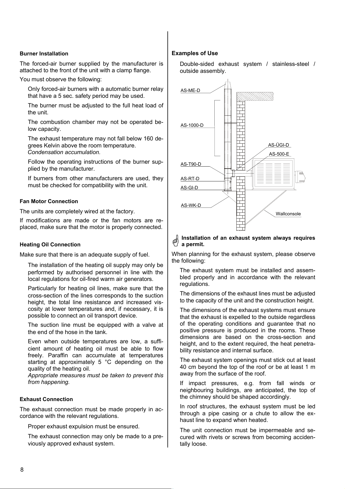
Double-sided exhaust system / stainless-steel /
outside assembly.
AS-ME-D
AS-1000-D
AS-ÜGI-D
AS-500-E
AS-T90-D
AS-RT-D
AS-GI-D
AS-WK-D
Wallconsole
Heating Oil Connection
Make sure that there is an adequate supply of fuel.
The installation of the heating oil supply may only be
performed by authorised personnel in line with the
local regulations for oil-fired warm air generators.
Particularly for heating oil lines, make sure that the
cross-section of the lines corresponds to the suction
height, the total line resistance and increased vis-
cosity at lower temperatures and, if necessary, it is
possible to connect an oil transport device.
The suction line must be equipped with a valve at
the end of the hose in the tank.
Even when outside temperatures are low, a suffi-
cient amount of heating oil must be able to flow
freely. Paraffin can accumulate at temperatures
starting at approximately 5 °C depending on the
quality of the heating oil.
Appropriate measures must be taken to prevent this
from happening.
Exhaust Connection
The exhaust connection must be made properly in ac-
cordance with the relevant regulations.
Proper exhaust expulsion must be ensured.
The exhaust connection may only be made to a pre-
viously approved exhaust system.
Installation of an exhaust system always requires
a permit.
When planning for the exhaust system, please observe
the following:
The exhaust system must be installed and assem-
bled properly and in accordance with the relevant
regulations.
The dimensions of the exhaust lines must be adjusted
to the capacity of the unit and the construction height.
The dimensions of the exhaust systems must ensure
that the exhaust is expelled to the outside regardless
of the operating conditions and guarantee that no
positive pressure is produced in the rooms. These
dimensions are based on the cross-section and
height, and to the extent required, the heat penetra-
bility resistance and internal surface.
The exhaust system openings must stick out at least
40 cm beyond the top of the roof or be at least 1 m
away from the surface of the roof.
If impact pressures, e.g. from fall winds or
neighbouring buildings, are anticipated, the top of
the chimney should be shaped accordingly.
In roof structures, the exhaust system must be led
through a pipe casing or a chute to allow the ex-
haust line to expand when heated.
The unit connection must be impermeable and se-
cured with rivets or screws from becoming acciden-
tally loose.
8
Page 9
Starting
Heating Mode
The exhaust system must be attached securely and
properly according to the manufacturer’s specifica-
tions.
It is preferable to have a horizontal exhaust line that
is as short as possible (Incline 2 % = 2 cm/m).
You should plan to have a closable opening for per-
forming measurements at a distance of 2 x
haust pipe behind the unit connection. Under certain
circumstances, it is possible to measure the exhaust
opening.
Make sure to maintain a safe distance to flamma-
ble materials!
ex-
Initial operation
Initial operation of the unit and its forced-air burner
must be performed by the manufacturer or one of its
authorised service representatives. During this process,
all regulating, control and safety mechanisms must be
checked to ensure that they are functioning properly
and set correctly.
Oil fired units may only be put into initial operation by
authorised personnel.
Make sure that the fan’s screws and bolts and
burner attachments are secure.
Open the blow-out grille if necessary and adjust it as
required.
Check the settings of the safety devices.
The unit runs fully automatically with the temperature
which has been pre-selected.
1. Turn the customer-supplied main
switch or the fuse on.
2. Open the fuel supply.
3. Set the operating switch to “I”.
The green operating light lights up.
4. Pre-select desired room temperature
on the room thermostat.
Room thermostat as an REMKO ac-
cessory.
Ventilation
In this position only the supply air fan runs and the unit
can be used for air circulation.
1. Set the operating switch to “II”.
2. Keep in mind that the unit’s fan runs
continuously.
It is not possible to control it with a
thermostat
Steps following initial operation
Keep a protocol of measurements and submit it to
the operator for safekeeping. Familiarise the opera-
tor with the system
Give the statement confirming the authorised com-
pany status and the company certificate of the re-
spective installation company to the relevant authori-
ties.
.
Adjust the throughput for the heating oil or gas to
meet the heating capacity of the unit.
See the unit’s type plate.
Switch the customer-supplied main switch or fuse on.
Set the burner to the optimum values in accordance
with the manufacturer’s specifications.
Measure the chimney draught when cold and hot.
Important information about corrosion in the heat-
exchanger.
The exhaust gas temperature difference may not
fall below 160 Kelvin.
This keeps the temperature from falling below the dew
point and prevents the resulting corrosion in the heat-
exchanger.
If the unit is not set to its rated heat load or it is too
large for the necessary heat requirements, the
burner only runs in cyclical operation. Because the
required operating temperature is not reached in cy-
clical operation, more condensation accumulates
and there is more corrosion in the heat-exchanger.
Unit Shut Down
Set the operating switch to “0”.
The green operating light goes out.
Keep in mind that the air supply fan continues running
to cool down the heat-exchanger and can run several
times before the unit is finally switched off.
Never interrupt (except in emergency situations)
the power supply until the cool-down phase is
completely finished. Our guarantee does not cover
damages caused to the unit by overheating.
If the unit is taken out of operation for a
longer period of time, the customer-
supplied main switch or the fuse should be
switched off and the fuel supply closed off.
9
Page 10
Maintenance and Service
The operator must have the unit checked and serviced
as necessary, at least once a year, by a representative
of the manufacturing company or another authorised
individual in accordance with the operating conditions.
Prior to doing any maintenance or repair work on
the unit, unplug it from the power supply. It is not
adequate to switch off the unit with the operating
switch!
Dust and dirt must be cleaned from the unit including
from the heat-exchanger, combustion chamber and
forced-air burner. Combustion residue in the com-
bustion chamber and in the heat-exchanger must be
removed.
Parts that wear out, e.g. flue gas brakes, oil nozzles,
oil filter inserts, seals etc. must be checked, cleaned
and replaced if necessary.
Make sure to comply with waste gas emission limits
in accordance with regulations.
Important Information on Servicing the Unit
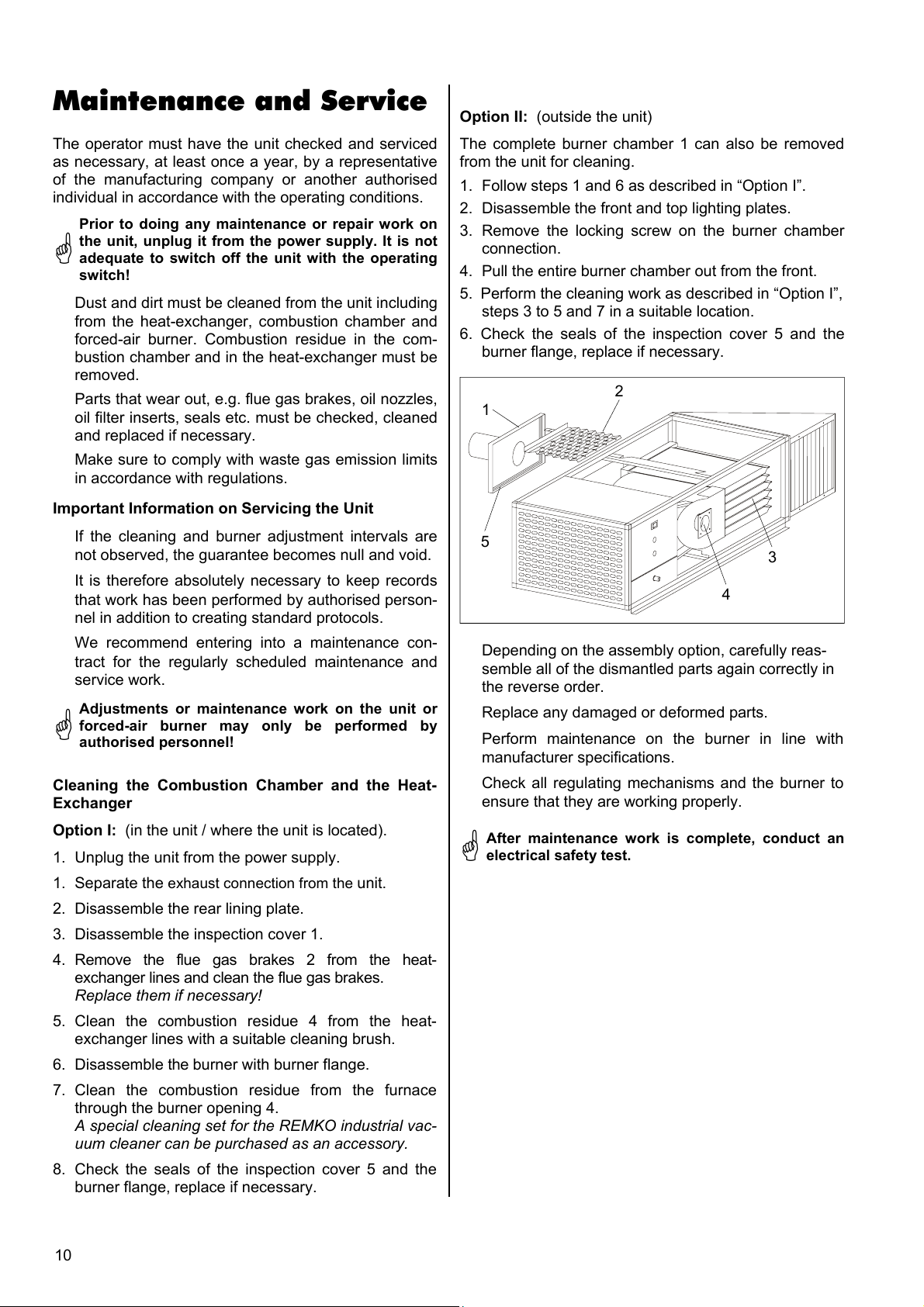
Option II: (outside the unit)
The complete burner chamber 1 can also be removed
from the unit for cleaning.
1. Follow steps 1 and 6 as described in “Option I”.
2. Disassemble the front and top lighting plates.
3. Remove the locking screw on the burner chamber
connection.
4. Pull the entire burner chamber out from the front.
5. Perform the cleaning work as described in “Option I”,
steps 3 to 5 and 7 in a suitable location.
6. Check the seals of the inspection cover 5 and the
burner flange, replace if necessary.
2
1
If the cleaning and burner adjustment intervals are
not observed, the guarantee becomes null and void.
It is therefore absolutely necessary to keep records
that work has been performed by authorised person-
nel in addition to creating standard protocols.
We recommend entering into a maintenance con-
tract for the regularly scheduled maintenance and
service work.
Adjustments or maintenance work on the unit or
forced-air burner may only be performed by
authorised personnel!
Cleaning the Combustion Chamber and the Heat-
Exchanger
Option I: (in the unit / where the unit is located).
1. Unplug the unit from the power supply.
1. Separate the exhaust connection from the unit.
2. Disassemble the rear lining plate.
3. Disassemble the inspection cover 1.
4. Remove the flue gas brakes 2 from the heat-
exchanger lines and clean the flue gas brakes.
Replace them if necessary!
5. Clean the combustion residue 4 from the heat-
exchanger lines with a suitable cleaning brush.
6. Disassemble the burner with burner flange.
7. Clean the combustion residue from the furnace
through the burner opening 4.
A special cleaning set for the REMKO industrial vac-
uum cleaner can be purchased as an accessory.
8. Check the seals of the inspection cover 5 and the
burner flange, replace if necessary.
5
3
4
Depending on the assembly option, carefully reas-
semble all of the dismantled parts again correctly in
the reverse order.
Replace any damaged or deformed parts.
Perform maintenance on the burner in line with
manufacturer specifications.
Check all regulating mechanisms and the burner to
ensure that they are working properly.
After maintenance work is complete, conduct an
electrical safety test.
10
Page 11
Troubleshooting
The unit does not start
Resetting the automatic burner relay
Check the power supply.
Check the operating and/or main switch.
Check that the burner is functioning properly.
Check the safety temperature limiter.
Keep in mind: before resetting the STB, it is abso-
lutely necessary to determine the reason it was acti-
vated and take appropriate measures
The following are possible causes:
- The unit could not cool down because the power
supply was interrupted. Even short interruptions
can activate the STB.
- The temperature of the air being blown out is too
high because the grilles have not been properly
adjusted.
- Air intakes and outlets are blocked.
- The fan was overloaded (the thermal contacts in
the fan motor were activated).
Check the room thermostat setting.
The room thermostat must be set higher than the
room temperature.
Set the operating switch to “II”.
If the air supply fan starts now, look for the problem
in the burner.
The burner does not start
Check that the operating switch is set to “Heizen”.
The green control light must be lit up.
Check the room thermostat setting.
The room thermostat must be set higher than the
room temperature.
Check that all shut-off fittings in the oil supply are
open.
Check whether the fuel filter is dirty.
Check that there is enough fuel in the fuel container.
Check whether paraffin has accumulated in the
heating oil.
This can occur even at 5 °C.
Check oil lines for damage.
Leaks can cause air intake.
Use suitable means to ensure that the safety tem-
perature limiter (STB) and the temperature monitor
(TW) are functioning properly.
Check the sensors and capillary pipes of the safety
temperature limiter (STB) and the temperature moni-
tor (TW) for damage and ensure that the sensor has
been properly positioned.
Check whether the red control light (burner malfunc-
tion) on the operating panel is lit up.
If the red control light (burner malfunction) is lit up, re-
lease the relay by pressing the malfunction button on
the automatic burner relay.
The malfunction light goes out and the burner tries to
start.
The red control light of the automatic burner relay also
blinks in a code which helps service personnel identify
the cause of the malfunction.
Remember that the oil-preheater causes a delayed
burner start.
Important information about resetting the burner
If, during the start phase, the unit is switched off
again due to a malfunction, it may only be restarted
after 5 minutes have elapsed.
Take any steps necessary to prevent another reset.
Danger of deflagration.
The problem must be fixed by authorised service
personnel!
For safety purposes, repair work on the electrical
components and the burner may only be per-
formed by authorised personnel.
The air supply fan does not start
Set the operating switch to “II”.
The air supply fan should now start.
Check the fan for smooth operation and any dirt.
Check the electric cord on the fan motor for damage.
Check whether the capacity of the fan was ex-
ceeded.
The thermal contacts in the fan motor have been ac-
tivated.
Check the operating capacitor of the fan.
Use suitable means to ensure that the fan control
thermostat (TR) are functioning properly.
After working on the unit, conduct an electrical
safety test.
Should the unit still not function properly after per-
forming these checks, please contact an author-
ised service centre.
11
Page 12
Technical Data
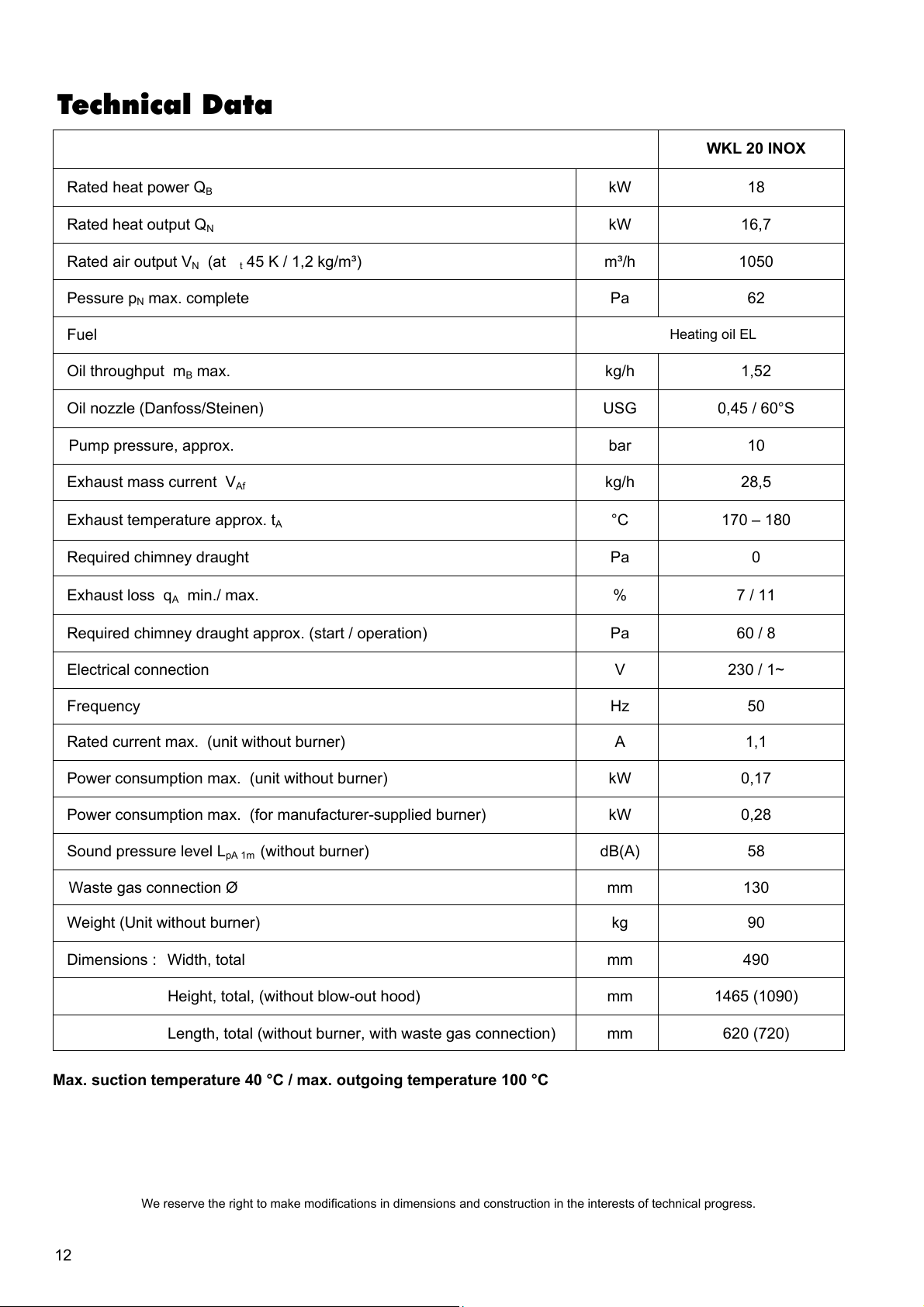
WKL 20 INOX
Rated heat power QB kW 18
Rated heat output QN kW 16,7
Rated air output VN (at t 45 K / 1,2 kg/m³)
m³/h 1050
Pessure pN max. complete Pa 62
Fuel
Heating oil EL
Oil throughput mB max. kg/h 1,52
Oil nozzle (Danfoss/Steinen) USG 0,45 / 60°S
Pump pressure, approx. bar 10
Exhaust mass current V
kg/h 28,5
Af
Exhaust temperature approx. tA °C 170 – 180
Required chimney draught Pa 0
Exhaust loss qA min./ max. % 7 / 11
Required chimney draught approx. (start / operation) Pa 60 / 8
Electrical connection V 230 / 1~
Frequency Hz 50
Rated current max. (unit without burner) A 1,1
Power consumption max. (unit without burner) kW 0,17
Power consumption max. (for manufacturer-supplied burner) kW 0,28
Sound pressure level L
(without burner) dB(A) 58
pA 1m
Waste gas connection Ø mm 130
Weight (Unit without burner) kg 90
Dimensions : Width, total mm 490
Height, total, (without blow-out hood) mm 1465 (1090)
Length, total (without burner, with waste gas connection) mm 620 (720)
Max. suction temperature 40 °C / max. outgoing temperature 100 °C
12
We reserve the right to make modifications in dimensions and construction in the interests of technical progress.
Page 13
Wiring Diagram
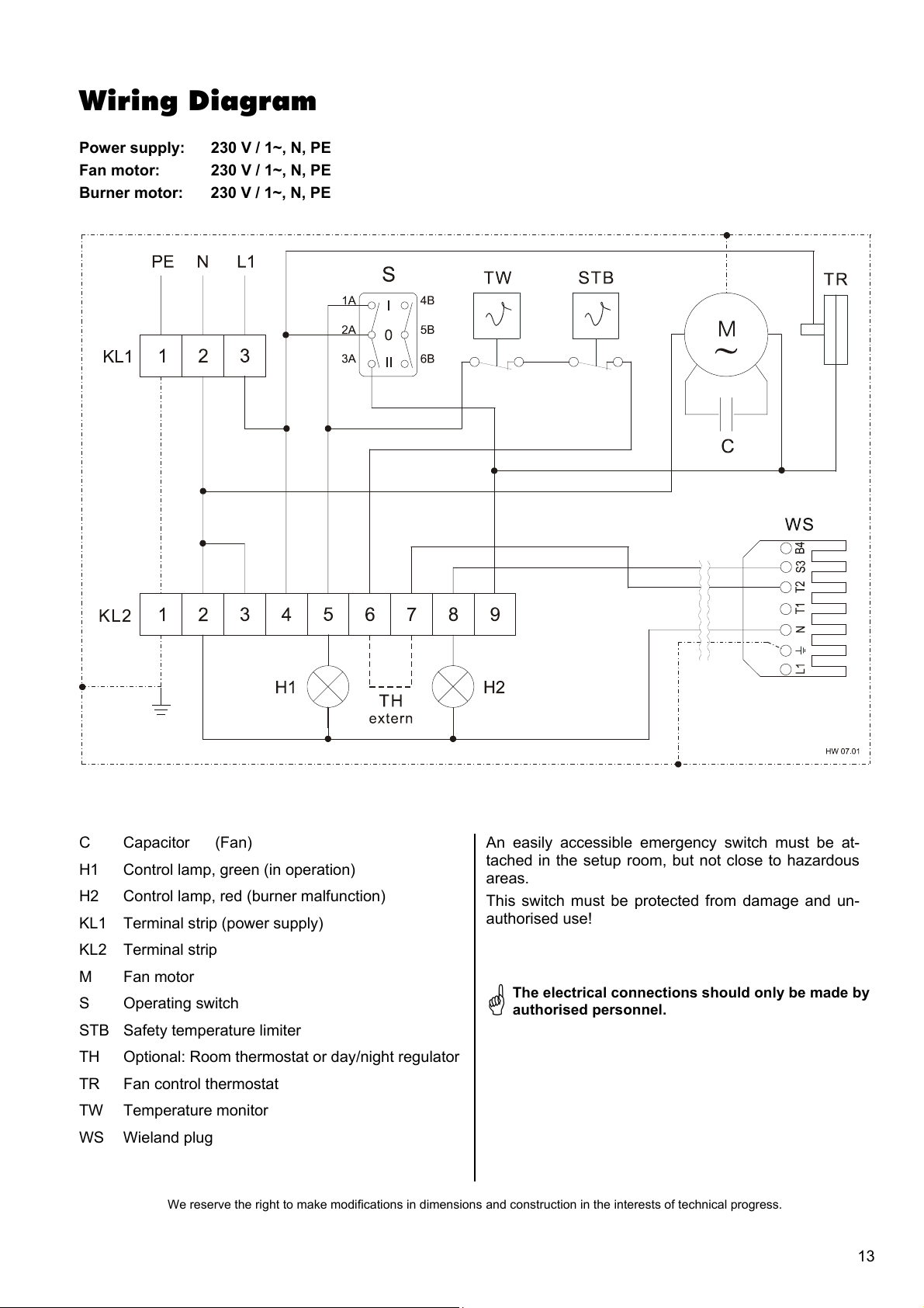
Power supply: 230 V / 1~, N, PE
Fan motor: 230 V / 1~, N, PE
Burner motor: 230 V / 1~, N, PE
C Capacitor (Fan)
H1 Control lamp, green (in operation)
H2 Control lamp, red (burner malfunction)
KL1 Terminal strip (power supply)
KL2 Terminal strip
M Fan motor
S Operating switch
STB Safety temperature limiter
TH Optional: Room thermostat or day/night regulator
TR Fan control thermostat
TW Temperature monitor
WS Wieland plug
We reserve the right to make modifications in dimensions and construction in the interests of technical progress.
An easily accessible emergency switch must be at-
tached in the setup room, but not close to hazardous
areas.
This switch must be protected from damage and un-
authorised use!
The electrical connections should only be made by
authorised personnel.
13
Page 14
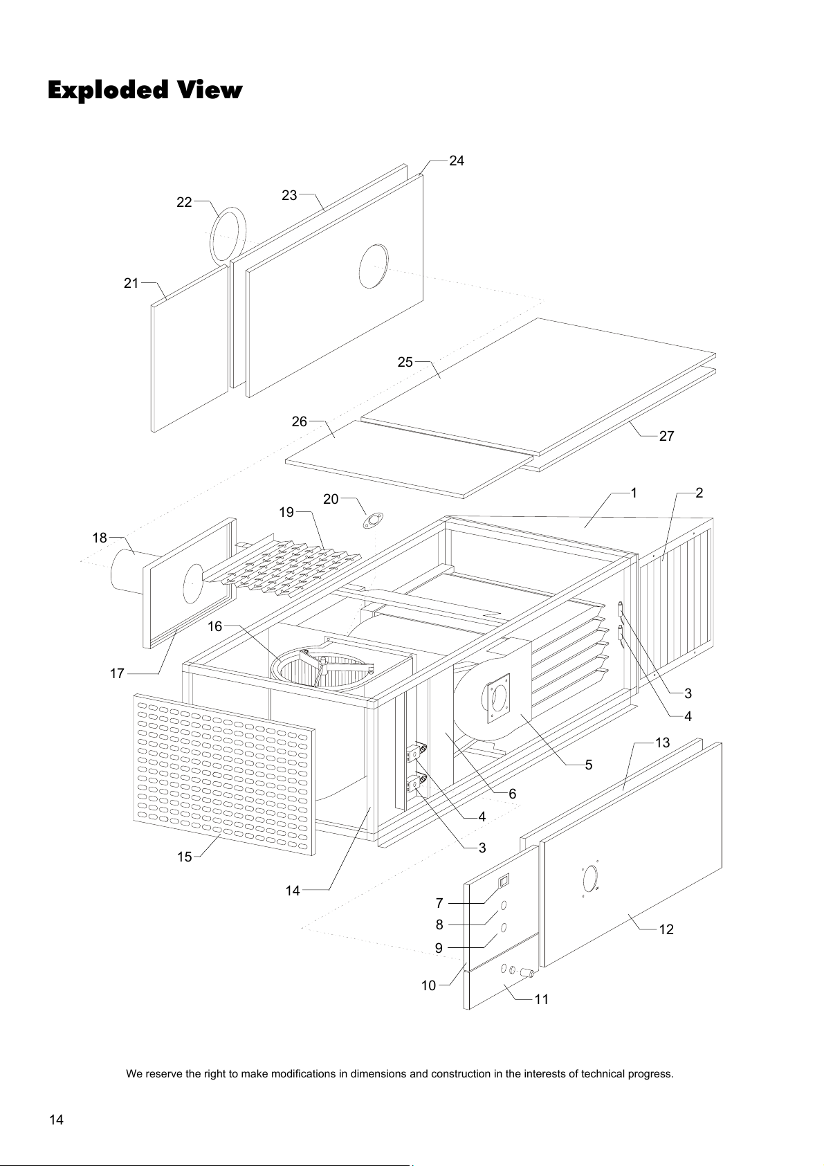
Exploded View
24
18
21
22
23
19
26
20
25
27
1 2
17
15
16
14
10
7
8
9
3
4
13
5
6
4
3
12
11
14
We reserve the right to make modifications in dimensions and construction in the interests of technical progress.
Page 15
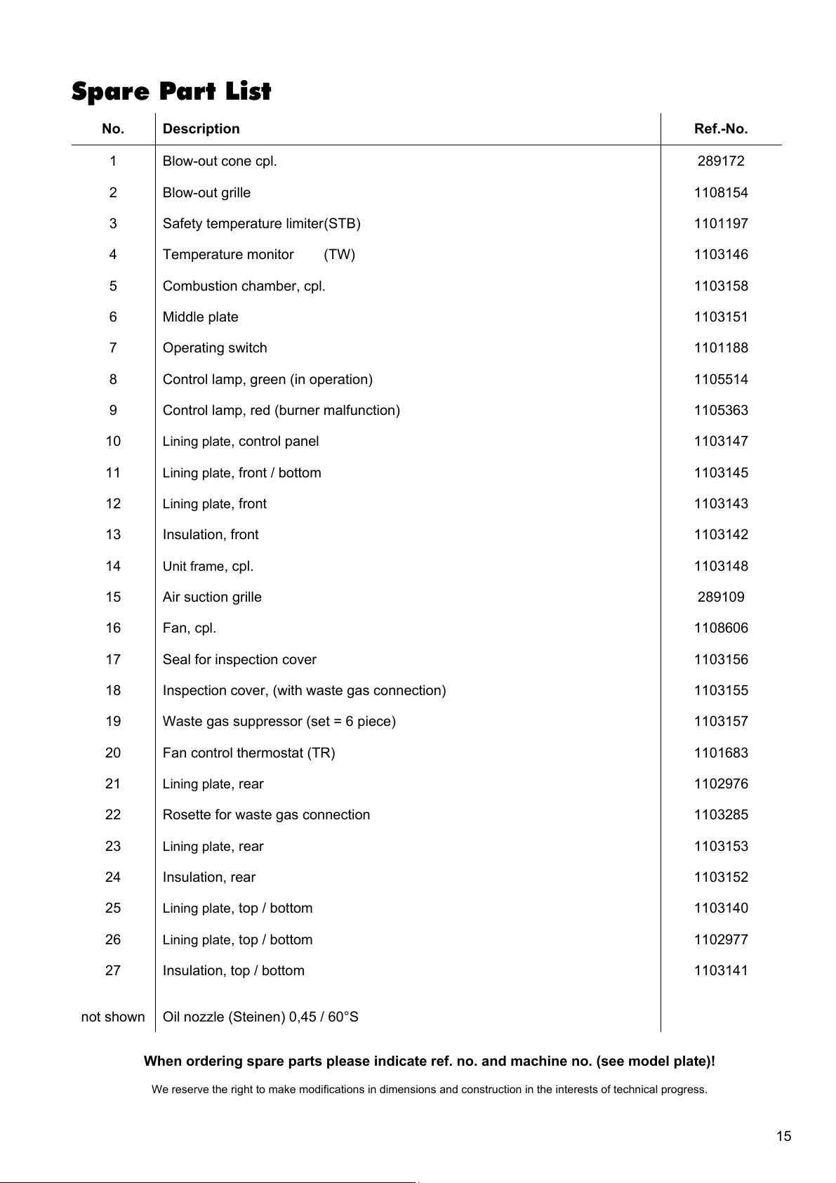
Spare Part List
No. Description Ref.-No.
1 Blow-out cone cpl. 289172
2 Blow-out grille 1108154
3 Safety temperature limiter (STB) 1101197
4 Temperature monitor (TW) 1103146
5 Combustion chamber, cpl. 1103158
6 Middle plate 1103151
7 Operating switch 1101188
8 Control lamp, green (in operation) 1105514
9 Control lamp, red (burner malfunction) 1105363
10 Lining plate, control panel 1103147
11 Lining plate, front / bottom 1103145
12 Lining plate, front 1103143
13 Insulation, front 1103142
14 Unit frame, cpl. 1103148
15 Air suction grille 289109
16 Fan, cpl. 1108606
17 Seal for inspection cover 1103156
18 Inspection cover, (with waste gas connection) 1103155
19 Waste gas suppressor (set = 6 piece) 1103157
20 Fan control thermostat (TR) 1101683
21 Lining plate, rear 1102976
22 Rosette for waste gas connection 1103285
23 Lining plate, rear 1103153
24 Insulation, rear 1103152
25 Lining plate, top / bottom 1103140
26 Lining plate, top / bottom 1102977
27 Insulation, top / bottom 1103141
not shown Oil nozzle (Steinen) 0,45 / 60°S
When ordering spare parts please indicate ref. no. and machine no. (see model plate)!
We reserve the right to make modifications in dimensions and construction in the interests of technical progress.
15
Page 16
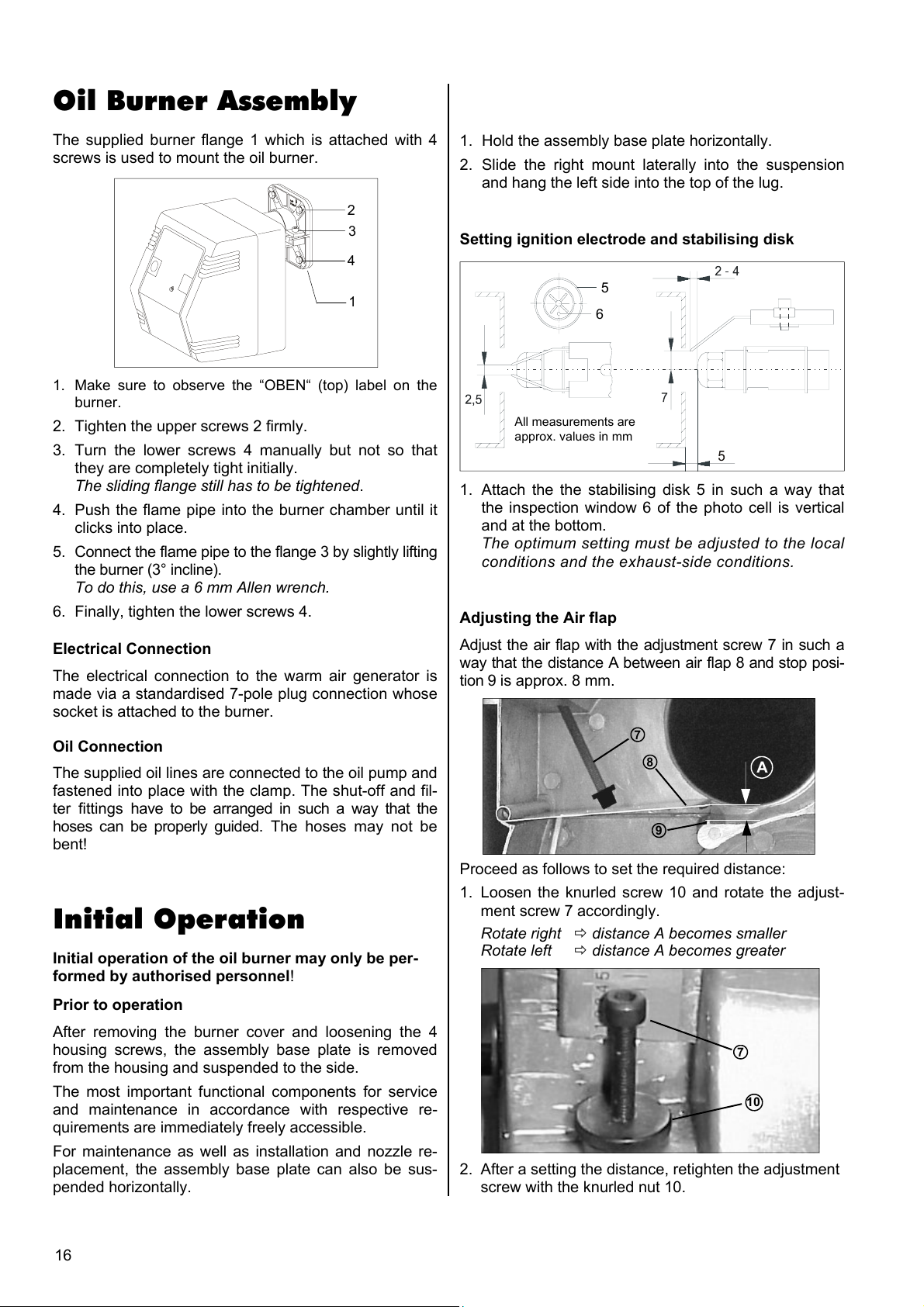
Oil Burner Assembly
The supplied burner flange 1 which is attached with 4
screws is used to mount the oil burner.
2
3
4
1. Hold the assembly base plate horizontally.
2. Slide the right mount laterally into the suspension
and hang the left side into the top of the lug.
Setting ignition electrode and stabilising disk
1
1. Make sure to observe the “OBEN“ (top) label on the
burner.
2. Tighten the upper screws 2 firmly.
3. Turn the lower screws 4 manually but not so that
they are completely tight initially.
The sliding flange still has to be tightened.
4. Push the flame pipe into the burner chamber until it
clicks into place.
5. Connect the flame pipe to the flange 3 by slightly lifting
the burner (3° incline).
To do this, use a 6 mm Allen wrench.
6. Finally, tighten the lower screws 4.
Electrical Connection
The electrical connection to the warm air generator is
made via a standardised 7-pole plug connection whose
socket is attached to the burner.
Oil Connection
The supplied oil lines are connected to the oil pump and
fastened into place with the clamp. The shut-off and fil-
ter fittings have to be arranged in such a way that the
hoses can be properly guided. The hoses may not be
bent!
Initial Operation
Initial operation of the oil burner may only be per-
formed by authorised personnel!
5
6
All measurements are
approx. values in mm
1. Attach the the stabilising disk 5 in such a way that
the inspection window 6 of the photo cell is vertical
and at the bottom.
The optimum setting must be adjusted to the local
conditions and the exhaust-side conditions.
Adjusting the Air flap
Adjust the air flap with the adjustment screw 7 in such a
way that the distance A between air flap 8 and stop posi-
tion 9 is approx. 8 mm.
7
8
9
A
Proceed as follows to set the required distance:
1. Loosen the knurled screw 10 and rotate the adjust-
ment screw 7 accordingly.
Rotate right distance A becomes smaller
Rotate left distance A becomes greater
Prior to operation
After removing the burner cover and loosening the 4
housing screws, the assembly base plate is removed
from the housing and suspended to the side.
The most important functional components for service
and maintenance in accordance with respective re-
quirements are immediately freely accessible.
For maintenance as well as installation and nozzle re-
placement, the assembly base plate can also be sus-
pended horizontally.
16
7
10
2. After a setting the distance, retighten the adjustment
screw with the knurled nut 10.
Page 17
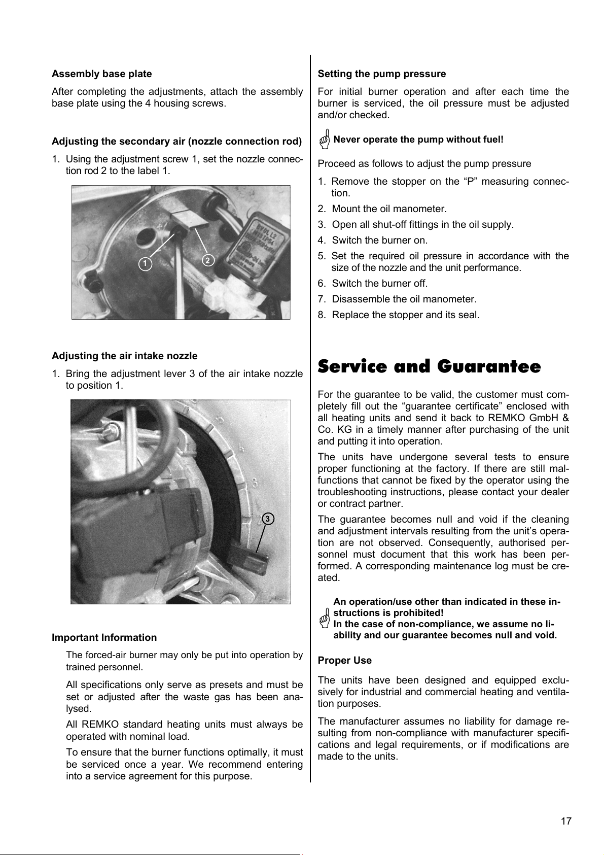
Assembly base plate
Setting the pump pressure
After completing the adjustments, attach the assembly
base plate using the 4 housing screws.
Adjusting the secondary air (nozzle connection rod)
1. Using the adjustment screw 1, set the nozzle connec-
tion rod 2 to the label 1.
1
Adjusting the air intake nozzle
1. Bring the adjustment lever 3 of the air intake nozzle
to position 1.
2
3
For initial burner operation and after each time the
burner is serviced, the oil pressure must be adjusted
and/or checked.
Never operate the pump without fuel!
Proceed as follows to adjust the pump pressure
1. Remove the stopper on the “P” measuring connec-
tion.
2. Mount the oil manometer.
3. Open all shut-off fittings in the oil supply.
4. Switch the burner on.
5. Set the required oil pressure in accordance with the
size of the nozzle and the unit performance.
6. Switch the burner off.
7. Disassemble the oil manometer.
8. Replace the stopper and its seal.
Service and Guarantee
For the guarantee to be valid, the customer must com-
pletely fill out the “guarantee certificate” enclosed with
all heating units and send it back to REMKO GmbH &
Co. KG in a timely manner after purchasing of the unit
and putting it into operation.
The units have undergone several tests to ensure
proper functioning at the factory. If there are still mal-
functions that cannot be fixed by the operator using the
troubleshooting instructions, please contact your dealer
or contract partner.
The guarantee becomes null and void if the cleaning
and adjustment intervals resulting from the unit’s opera-
tion are not observed. Consequently, authorised per-
sonnel must document that this work has been per-
formed. A corresponding maintenance log must be cre-
ated.
Important Information
The forced-air burner may only be put into operation by
trained personnel.
All specifications only serve as presets and must be
set or adjusted after the waste gas has been ana-
lysed.
All REMKO standard heating units must always be
operated with nominal load.
To ensure that the burner functions optimally, it must
be serviced once a year. We recommend entering
into a service agreement for this purpose.
An operation/use other than indicated in these in-
structions is prohibited!
In the case of non-compliance, we assume no li-
ability and our guarantee becomes null and void.
Proper Use
The units have been designed and equipped exclu-
sively for industrial and commercial heating and ventila-
tion purposes.
The manufacturer assumes no liability for damage re-
sulting from non-compliance with manufacturer specifi-
cations and legal requirements, or if modifications are
made to the units.
17
Page 18
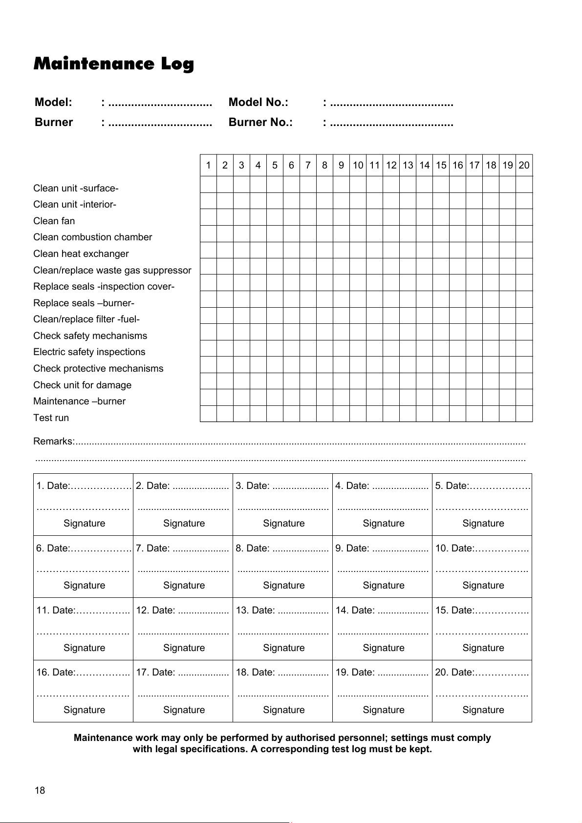
Maintenance Log
Model: : ................................ Model No.: : ......................................
Burner : ................................ Burner No.: : ......................................
1 2 3 4 5 6 7 8 9 10 11 12 13 14 15 16 17 18 19 20
Clean unit -surface-
Clean unit -interior-
Clean fan
Clean combustion chamber
Clean heat exchanger
Clean/replace waste gas suppressor
Replace seals -inspection cover-
Replace seals –burner-
Clean/replace filter -fuel-
Check safety mechanisms
Electric safety inspections
Check protective mechanisms
Check unit for damage
Maintenance –burner
Test run
Remarks:.......................................................................................................................................................................
......................................................................................................................................................................................
1. Date:………………. 2. Date: ..................... 3. Date: ..................... 4. Date: ..................... 5. Date:……………….
……………………….. .................................. .................................. .................................. ………………………..
Signature Signature Signature Signature Signature
6. Date:………………. 7. Date: ..................... 8. Date: ..................... 9. Date: ..................... 10. Date:……………..
……………………….. .................................. .................................. .................................. ………………………..
Signature Signature Signature Signature Signature
11. Date:…………….. 12. Date: ................... 13. Date: ................... 14. Date: ................... 15. Date:……………..
……………………….. .................................. .................................. .................................. ………………………..
Signature Signature Signature Signature Signature
16. Date:…………….. 17. Date: ................... 18. Date: ................... 19. Date: ................... 20. Date:……………..
……………………….. .................................. .................................. .................................. ………………………..
Signature Signature Signature Signature Signature
18
Maintenance work may only be performed by authorised personnel; settings must comply
with legal specifications. A corresponding test log must be kept.
Page 19

Page 20
REMKO GmbH & Co. KG
Klima- und Wärmetechnik
D-32791 Lage • Im Seelenkamp 12
D-32777 Lage • PO Box 1827
Phone +49 5232 606 - 0
Fax +49 5232 606 260
E-Mail [email protected]
Internet www.remko.de
 Loading...