

Page 1
REMKO RKV 10 W / 13 W / 18 W / 24 W
Multi-purpose room air conditioners
Operation
Technology
Spare Parts
Edition GB – P05
REMKO – powerful like a bear.
Page 2

Page 3
Operating Instructions
Read these instructions carefully before setting up/operating the unit!
Our guarantee becomes null and void if the unit is used, set up
or maintained improperly, or if modifications are made to the
supplied unit without our prior consent.
Subject to alterations!
Split-design, multi-purpose room air conditioners
Wall-mounted units REMKO RKV 10 W / 13 W / 18 W / 24 W
Contents Page
Safety Hints 4
Transport and Packaging 4
Description of Device 4
Operation 5
System Structure 8
Shutting Down the Unit 8
Maintenance and Service 8
Troubleshooting 9
Technical Data 10
Dimensions 10
Assembly Instructions for Service Personnel 11
Installation 12
Always keep these operating instructions near or on the unit!
Contents Page
Impermeability Check 14
Adding Refrigerant 14
Electrical Connection 14
Condensation Connection 15
External Condensation Pump 15
Prior to Initial Operation 17
Initial Operation 17
Environment and Recycling 18
Customer Service and Guarantee 18
Internal Wiring Diagram 18
Initial Operation Certification 19
3
Page 4
Safety Hints
Extensive tests have been conducted on the material,
functionality and quality of these units before they were
shipped. These units may only be used in accordance
with their intended purpose. Hazards may arise if the
units are used improperly.
Please make sure to follow these safety instructions.
à Never operate the indoor unit outside or without the
air filter.
à Make sure that personnel trained in the operation of
the air conditioner check the unit for visible defects
on the operating and safety mechanisms each time
before putting it into operation.
à Before performing any work on the unit, the power
cord must be unplugged and the unit secured
against being switched on by unauthorised persons.
à Operate the units only when assembled and for their
intended purpose.
à Keep in mind that it is dangerous to remove covers
protective grilles, etc., during operation; this can lead
to uncontrolled operating situations.
à The indoor unit and the outdoor part of the REMKO
air-conditioners have been technically adjusted to
one another.
If third-party components are used, the guarantee
becomes null and void.
à Operate the units exclusively within the permissible
operating ranges.
Pay attention to surrounding temperatures.
à Make sure that the unit is kept at a safe distance
from flammable materials.
à Do not install the inside unit close to heaters or be-
hind curtains and drapes.
Maintain the minimum safety distances indicated!
à Ensure that the air intake and outlet openings are al-
ways clear of foreign objects.
à Do not insert any objects into the air intake and out-
let openings.
à Do not place any objects on top of the units.
à Never operate the units in rooms susceptible to ex-
plosions.
à The units are also not suitable for operation in rooms
containing large amounts of dust or aggressive air.
à Do not use flammable sprays such as hair spray or
spray paint in the direct vicinity of the units.
à Do not operate the units if the atmosphere is con-
taminated by oil, sulfur or salt.
à Do not expose the unit to direct streams of water.
High-pressure cleaners, etc.
à Protect the indoor unit and the remote control from
moisture and direct sunlight.
à Never open the units’ housing!
This may cause an electric shock.
à Regularly check that condensation is not blocked
from flowing out of the unit.
à Make sure that the outdoor part is equipped with a
safety mechanism which prevents the condenser
from being damaged caused by the unit switching
back on right away after it has been switched off.
The unit may only be switched back on after 3 minutes.
à Cleaning and minor maintenance work made only be
performed by the operator or an authorised person
designated by him in accordance with the instructions contained in the section "Maintenance and
Service".
à All REMKO air conditioners are supplied with the en-
vironmentally-friendly refrigerant R 407C.
à Installation and repair work may only be performed
by authorised personnel.
Transport and Packaging
The unit is shipped in a stable transport box made of
cardboard. Please examine the unit when it is delivered.
Make note of any damage or missing parts on the shipping bill and notify the shipping company and your contract partner.
We do not assume any liability for subsequent complaints.
Description of Device
The room air-conditioners in the REMKO RKV 10 W,
13 W, 18 W and RKV 24 W series are split-design, wallmounted, direct-condensing units.
The way the air conditioning system works is quite simple; warm air is removed from the room to be cooled.
The environmentally-friendly refrigerant R 407C transports this warmth just as it does for all other REMKO
air-conditioning products.
The units primary function is to air-condition rooms.
They also filter and dehumidify the air, thus creating a
comfortable climate in the room. The units also have a
pure ventilation and dehumidification mode.
All units operate fully-automatically and offer a range of
other options thanks to their microprocessor control.
They are operated using the supplied infrared remote
control.
4
Page 5
Operation
Two to four seconds after the indoor unit has been connected to the power supply, operation can begin.
Inserting batteries into the remote control
Prior to initial operation, the batteries supplied with the
unit (2 type AAA batteries) must be inserted into the remote control.
1. Slide off the cover of the battery slot on the back of
the remote control and insert the batteries.
2. Make sure that the polarity is correct.
Use the labelling in the slot.
3. Close the battery slot again.
The remote control
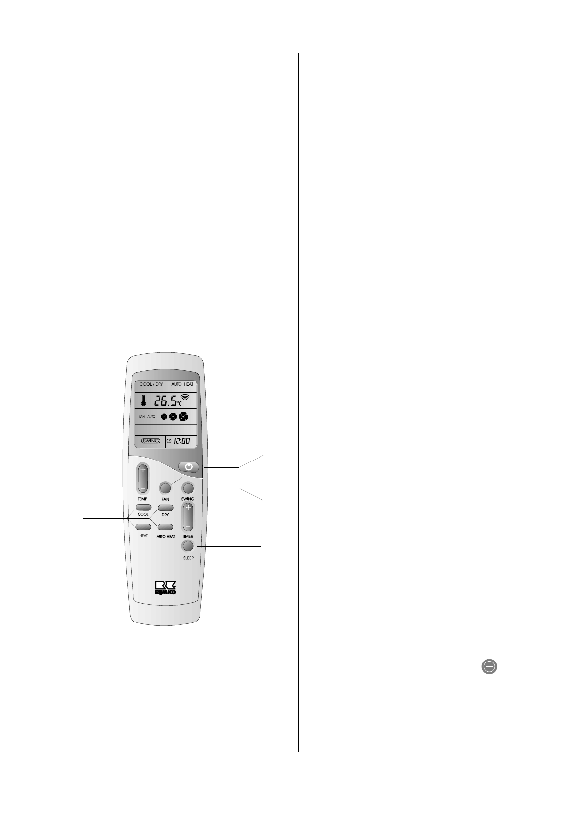
The room air conditioner is operated using the infrared
remote control.
A beep indicates that a button has been pressed and
the signal has been correctly received.
1
7
6
2
3
4
5
3 Swing button
When the unit is switched on (ON), the oscillating
blade improves air distribution of the outlet opening
in the room.
4 Timer button
You can program the unit to automatically switch on
or off within the next 24 hour-period with the Timer
button.
5 Sleep button
If the Sleep function is activated, the set room temperature increases by 1°C after one hour. This function can be reset by pressing any button.
6 Mode buttons 1 to 4
The room air-conditioner has 4 modes:
1. Cooling mode:
COOL button
In this mode, the warm air in the room is cooled
to the desired temperature. W hen the mechanism
which prevents the unit from switching back on
for approx. 3 minutes is active, the COMP. display blinks.
2. Heating mode:
HEAT button
Heating mode is not active for these units.
3. Dehumidification mode:
DRY button
In this mode, the room is primarily dehumidified
and the set temperature is maintained.
4. Automatic mode:
AUTO HEAT button
In this mode, the unit operates like it does in cooling mode. The difference between the point at
which it switches on and off (hysterisis) is higher
than in cooling mode.
7 Temp. button
The temperature button can be used to set the desired temperature in 0.5 °C increments between 15 °C
and 30 °C.
1 On / Off button
Press this button to turn the unit on.
The POWER display lights up.
2 Fan button
Set the fan speed you want with this button.
The following 4 speeds are available:
Automatic, low, medium and high.
Manual operation
The unit can be put into operation manually, e.g. if the
remote control is not operating properly or is lost.
For the RKV 10 W to RKV 18 W units, open the air intake grille and press the ON / OFF button on the right
side of the control panel.
For the RKV 24 W unit, press the button on the
front of the housing.
The following operating modes are then activated:
MODE : Auto mode TEMP. : 24°C
FAN: Automatic SWING: On
TIMER: Off
5
Page 6
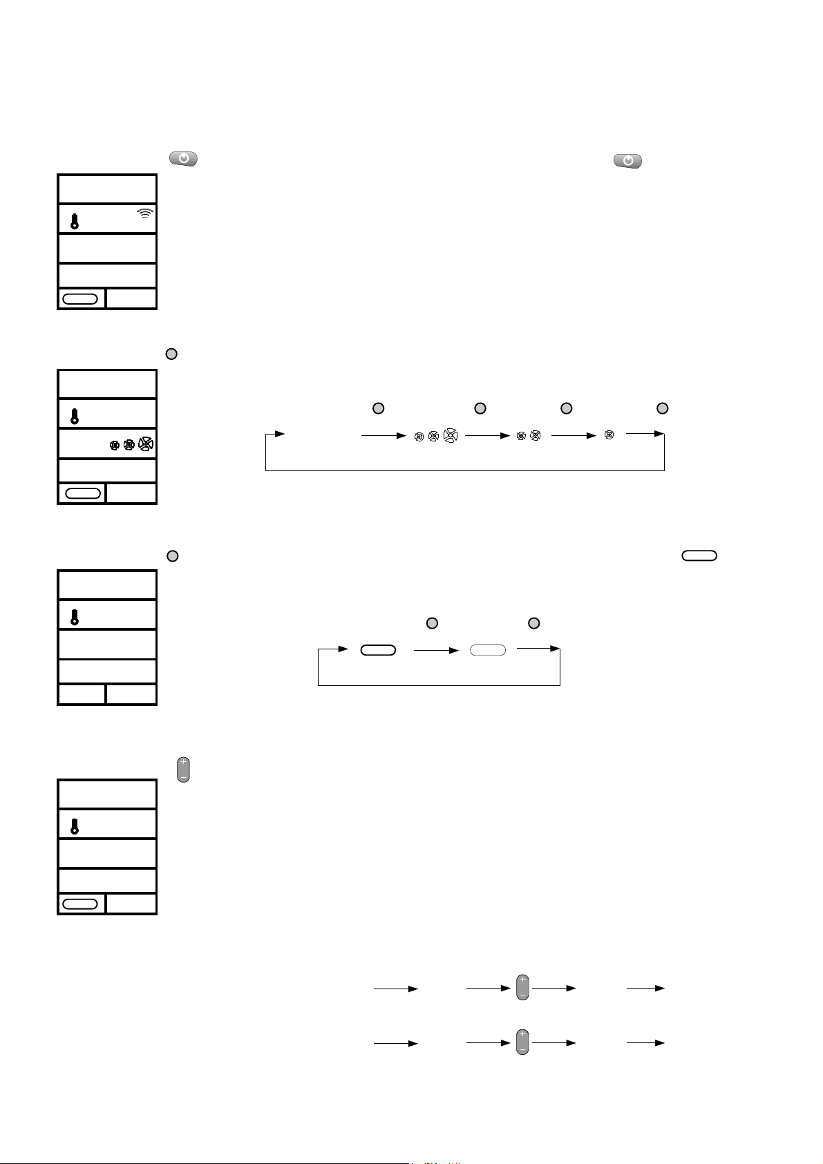
Button functionality
The following commands can be performed using the remote control. Point the remote control at the receiver on the
right side of the wall-mounted unit at a distance of no more than 7m.
On / Off button
COOL
°c
25.0
FAN AUTO
SWING
Fan button
COOL
°c
25.0
FAN
SWING
Swing button
COOL
°c
25.0
FAN AUTO
FAN
SWING
Activate and deactivate the indoor unit with the ON / OFF button
The current settings appear on the display:
1. FAN AUTO = Speed of the fan
2. SWING = Oscillating blade
3. 25.0 °C = Set temperature
4. COOL = Mode
When the FAN button is pressed, different-sized fan symbols or FAN AUTO are visible
on the display. The size of the symbol represents the speed of the fan. Each time the
button is pressed, the fan speed is reduced.
Functional process
FAN AUTO
The SWING button stops the oscillating blade. When switched on (Display ), the
FAN FAN FAN FAN
SWING
cooled air is distributed better in the room. The unit automatically distributes the air in a
vertical direction only. The air can only be set to be distributed horizontally by manually
adjusting the vertical plate fins.
Functional process
SWING
SWING SWING
Timer button
AUTO
°c
22.0
FAN AUTO
SWING
02:00
6
TIMER
The TIMER button is used to program the unit to switch on or off at a later time. If the
room air-conditioner is to be switched on at a later time, press the + or – button for
approximately 2 seconds when the unit is off.
In both operating modes, 12:0H appears in the lower right-hand corner of the display.
The desired length of time can be reduced or increased in 10 minute increments by
pressing the – or + button. After 3 seconds, the displayed length of time is saved.
When programming the unit to switch on with the timer function, the mode, the desired temperature and the fan speed of the last setting are transferred.
Once the programmed time has elapsed, the unit switches on or off automatically. Position the remote control in such a way that communication with the air-conditioner is
assured.
Functional process
Delayed start
Unit OFF
12.0H 02.00 01.59
TIMER
Delayed stop
Unit ON
12.0H
02.00 01.59
TIMER
Page 7
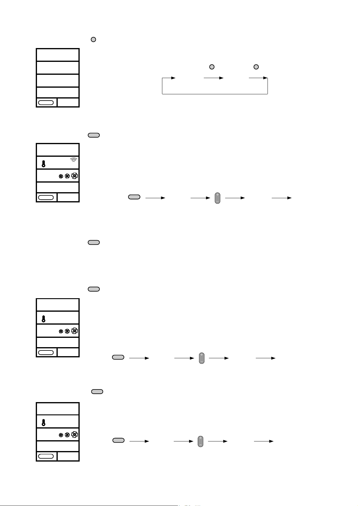
Sleep button
AUTO
SLP
FAN AUTO
SWING
SLEEP
By pressing the SLEEP button, the room temperature increases by 1 °C one hour after the function has been activated. This function can be cancelled by pressing any
button. The
Functional process
SLP sign disappears and the normal display appears.
/ any button
SLEEP SLEEP
°c
25.0
SLP
COOL mode
COOL
°c
25.0
FAN
SWING
HEAT mode
COOL/DRY mode
COOL / DRY
°c
25.0
FAN AUTO
SWING
COOL
HEAT
DRY
Use the COOL mode when you want to cool the room to the desired temperature.
Reduce the desired temperature by pressing the Temperature button in 0.5 °C increments. After you hear a beep, the COMP. display begins to blink for approximately
3 minutes. This waiting period is a forced pause to increase the service life of the
compressor and the outdoor part. Once the display stops blinking, the air-conditioner
begins working. If the temperature in the room falls 1 C° below the set temperature,
the regulator switches cooling off.
Functional process
COOL
COOL
25.0
TEMP.
COOL
15.5
COOLING
The HEAT mode is not active for these units.
The COOL / DRY mode dehumidifies the room in an unregulated fashion. The temperature of the plate fin exchanger of the indoor unit almost always falls below the
dew point of the air which causes the moisture in the air to condense on the plate fins.
The dehumidification capacity is based on the moisture in the air and the room temperature. After the DRY button has been pressed, the desired temperature can be selected and the unit begins working. The fan switches off at specific intervals to lower
the plate fin temperature. You can exit this mode by switching to a different one.
Functional process
DRY
COOL
25.0
TEMP.
COOL
15.5
DEHUMIDIFICATION
AUTO mode
AUTO
22.0
FAN AUTO
SWING
°c
AUTO HEAT
After pressing the AUTO HEAT button, AUTO appears on the display. The desired
room temperature is kept constant. If the set temperature is exceeded by 2 °C , cooling mode is activated. The operation is the same as it is in the COOL mode. We also
recommend setting the fan to FAN AUTO.
Functional process
AUTO HEAT
AUTO
15.5
TEMP.
AUTO
25.0
COOLING
7
Page 8
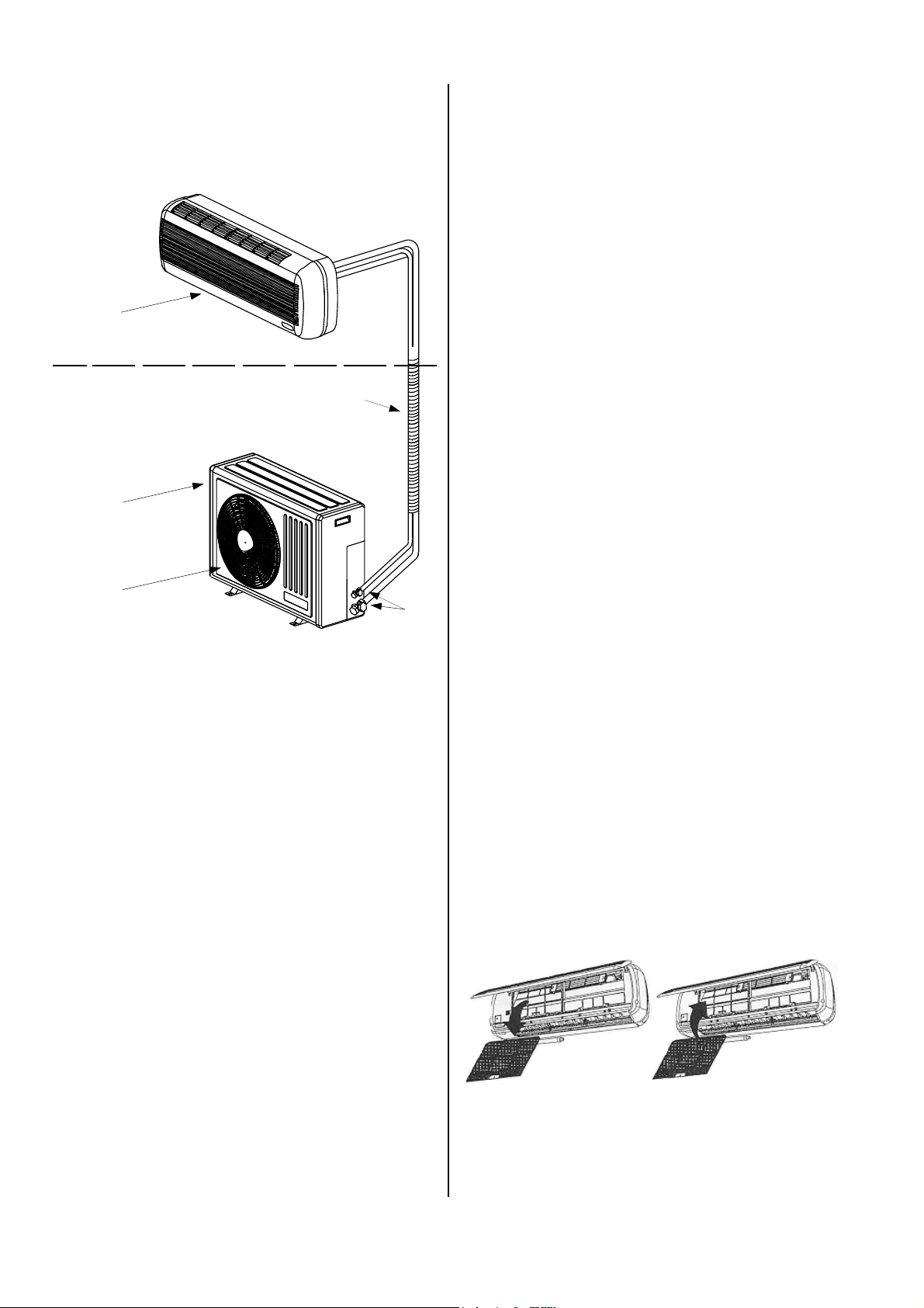
System Structure
The indoor unit is attached to the connections of the
outdoor part.
1
Inside area
Outside area
2
3
Maintenance and Service
Before any work on the units is performed, they
must be disconnected from the power supply and
prevented from being inadvertently switched on!
Regular care and the observation of a number of basic
rules will ensure the units’ long service life and reliable
operation.
à Keep the units free of dirt and other deposits.
à Clean the units with a damp cloth.
Do not expose the units to a direct stream of water.
à Do not use an abrasive cleaning agent or one that
contains solvent.
à If the units are extremely dirty, only use suitable
cleaning materials.
à Before and after the operating season, check
whether the diameter of the condensation lines has
become smaller as a result of dirt.
If so, they must be cleaned.
à Clean the air filters of the indoor unit at regular inter-
vals, more often if necessary, as described on this
page.
5
4
1 Indoor unit RKV 10 W (example)
2 Outdoor part RKS 510 (example)
3 Connecting lines
4 Shut-off valves
5 Condenser fan
Shutting Down the Unit
Temporary shutdown
1. Switch the indoor unit off using the remote control.
2. Disconnect the system with the main switch or fuse
protection from the power supply.
3. Check the indoor unit for visible damage.
4. Clean the indoor unit as described in the
“Maintenance and Service” section.
Never operate the indoor unit without the air filter.
The air filter prevents the plate fin exchanger of the
indoor unit from becoming dirty and the performance of the unit from being adversely affected.
à We recommend concluding a maintenance agree-
ment with a company who specialises in this type of
work.
This will guarantee that the system operates safely
at all times!
Cleaning the filters
Clean both air intake filters on the right and left at intervals of no longer than two weeks. If the air is extremely
dirty, shorten this timeframe accordingly.
Proceed as follows for cleaning:
1. Open the front of the unit by pushing the grille up
and locking it into place.
2. Lift the filters up and then pull them out.
Permanent shutdown
For environmental safety reasons, the air conditioners
may only be disassembled by authorised service centres.
REMKO GmbH & Co. KG or your contract partner would
be happy to provide you with the name of a service centre in your area.
8
3. Clean the filters using a standard vacuum cleaner.
4. Extreme dirt can be carefully removed with lukewarm
water.
Then let the filters air dry.
5. Replace the filters and close the grille.
Page 9
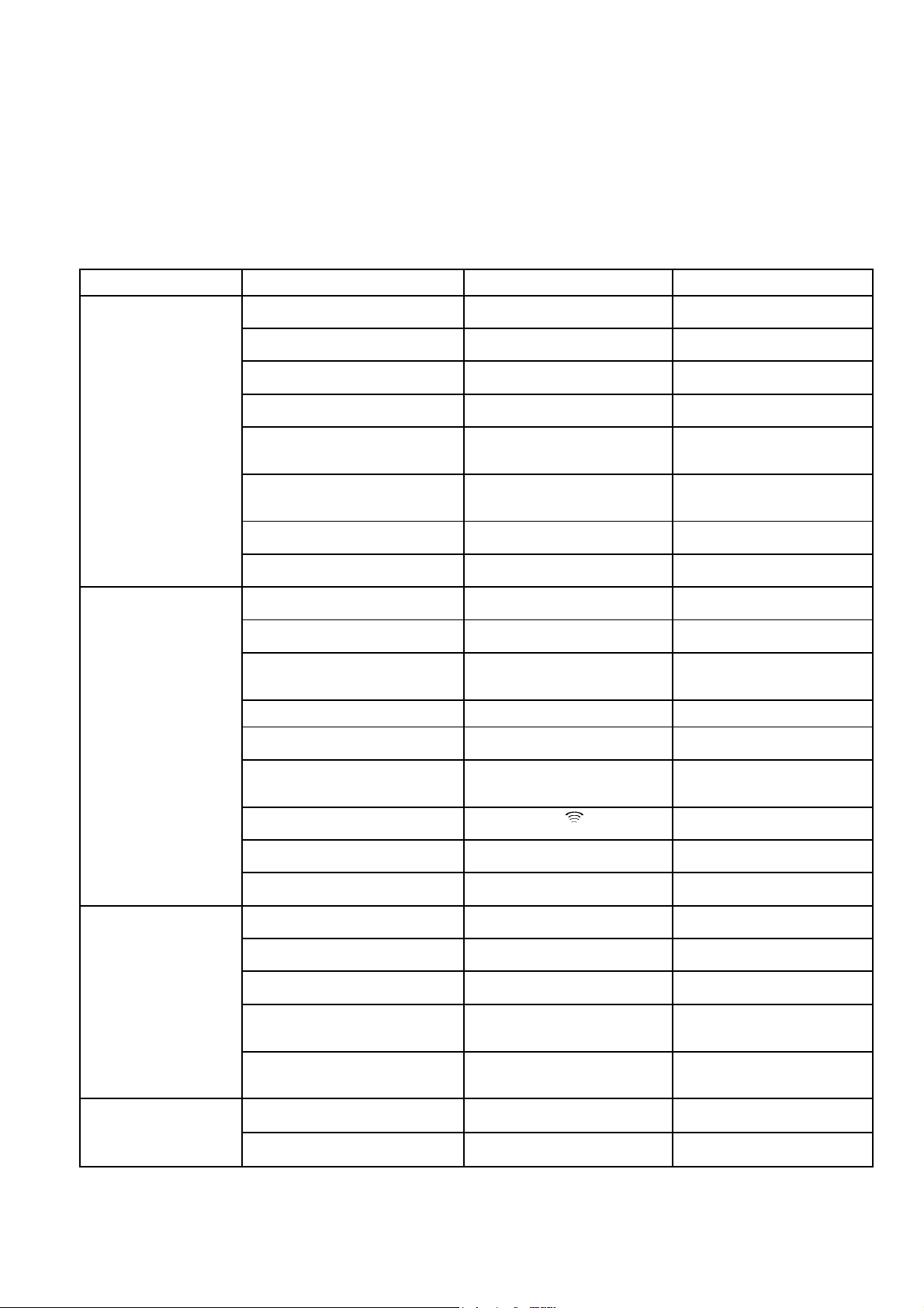
Troubleshooting
This unit has been designed based on state-of-the-art manufacturing methods and it has been tested repeatedly to
ensure that it is working properly. However, should problems occur, refer to the following list.
Please keep in mind that the indoor units are supplied with power via the outdoor parts. As a result, we recommend
also reading the section "Troubleshooting" in the operating instructions for the indoor unit.
Before any work on the units is performed, they must be disconnected from the power supply
(fuse or repair switch) and prevented from being inadvertently switched on
!
Problem
The unit does not start or
it switches itself off
automatically.
The indoor unit is not
responding to the remote
control.
Possible cause Check Remedy
Power failure, power too low, Are all other electrical components
Power fuse / power supply defective Are all currents for lighting func-
Power supply line damaged Are all other electrical components
Amount of time waited after switching
unit on was too short
Operating temperature too low / too
high
Excess current caused by thunderstorms
Problem with the external condensation pump
Sensors that are defective or not properly attached
Timer set to “ON” Is the timer set? Delete programming and wait for
Polarity of batteries incorrect after replacement
Transmission distance too great / reception blocked
Remote control defective Does the unit work in manual mode? Replace remote control
working?
tional?
working?
Did approx. 5 minutes elapse after
restarting?
Are the fans on the indoor unit and
outdoor part working?
Was there recently lightning in the
region ?
Did the pump switch off due to a
malfunction?
Is the indoor unit emitting a continuous signal?
Is the polarity correct? Insert batteries with the correct po-
Is the transmission signal at a distance of approx. 3 m when the button is pressed?
Check current and wait for the device to start again
Replace power fuse /
Switch on main switch
Maintenance by authorised personnel
Plan for longer waiting periods
Pay attention to temperature
ranges of indoor unit and outdoor
part
Switch the system off and then
back on again / Maintenance by
authorised personnel
Check pump and clean if necessary
Maintenance by authorised personnel
the unit to start
larity
Reduce distance to under 6 m and
change location
The device is either not
cooling at all or only
a little bit.
Condensation water
is leaking from the
indoor unit.
Too much direct sunlight on the receiver or transmitter
Electromagnetic fields are disrupting
transmission
Remote control buttons stuck / two
buttons pressed at once
Dead batteries in the remote control Are the batteries new? Is the display
Temperature setting too high Is the selected temperature above
Filter is dirty/ intake / outlet opening is
blocked by foreign bodies
Windows and doors are opened / increased amount of warm air or cold air
Cool mode is not set Does the Cool symbol (COOL)
Plate fins of the outdoor part are
blocked by foreign bodies
Cold cycle is not leak proof Is there a buildup of frost visible on
The drainage line of the condensation
collector is blocked / damaged
External condensation pump or float
regulator is defective
Does the function work in the
shade?
Does the unit work after potential
causes of disruption have been
eliminated?
Does the symbol appear on the
display?
incomplete?
the room temperature?
Have the filters been cleaned? Clean filters
Have there been changes in design
or use?
appear on the display?
Is the fan of the outdoor part work-
ing, are the plate fin exchangers
moving freely?
the plate fin exchangers of the indoor unit?
Can condensation drain freely? Clean the drainage line and the
Is the collector filled with water and
the pump is not working?
Place the transmitter or receiver in
the shade
No signal transmission when
sources of disruption are operated
simultaneously
Unstick button / only press one
button
Insert new batteries
Reduce selected temperature
Close the windows and doors /
mount additional systems
Correct the unit settings
Check the fan or winter regulation
mechanism, reduce air resistance
Maintenance by authorised personnel
condensation collector
Have pump checked by authorised
service centre
Should the unit still not be working despite these checks, please contact an authorised service centre.
9
Page 10
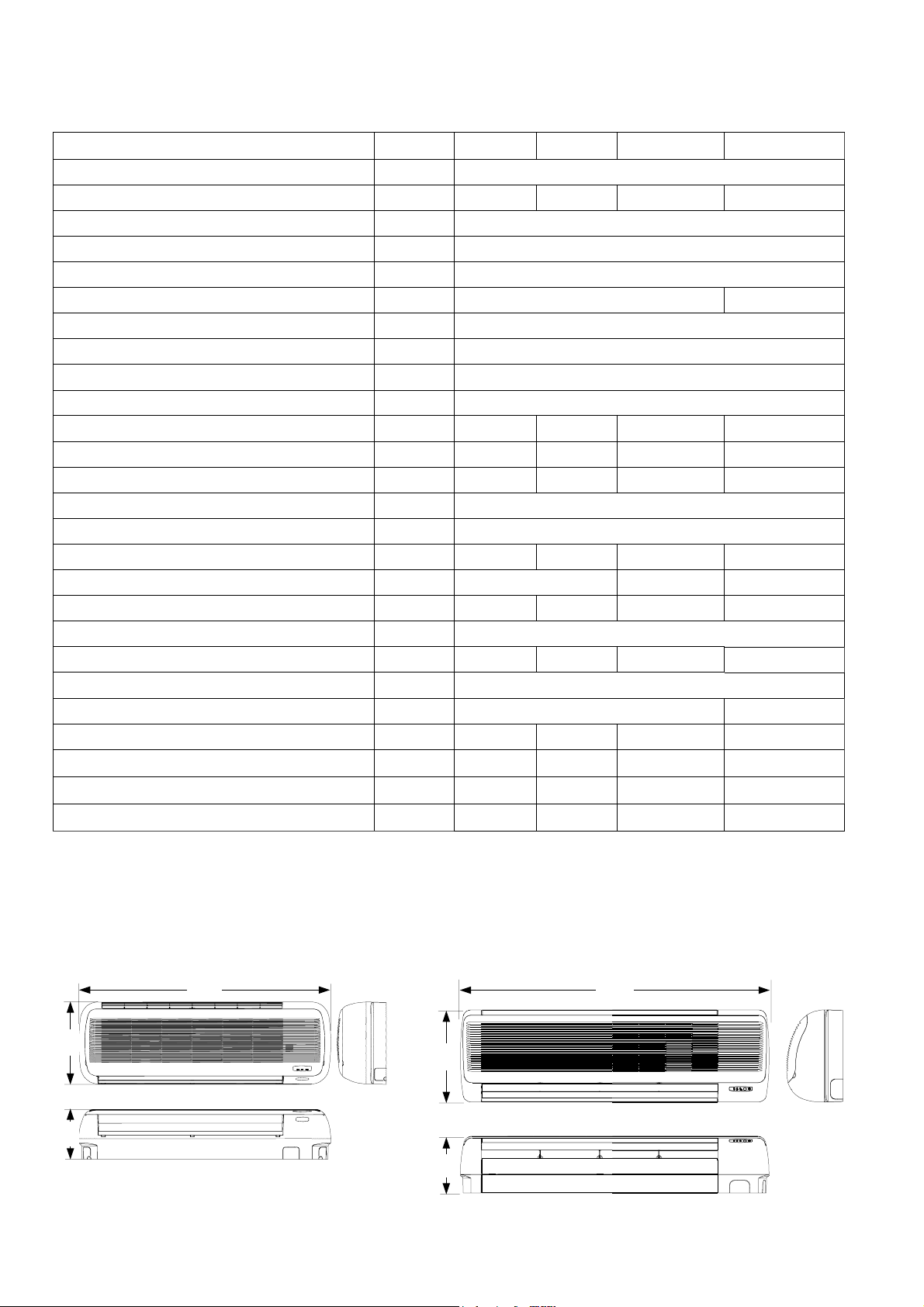
Technical Data
Type RKV 10 W RKV 13 W RKV 18 W
Cooling capacity
Area of use room size
Refrigerant
Refrigerant pressure max. / min.
Connection injection line
Connection intake line
Line length max.
High difference max.
Additional amount to add for 5 m or longer
Electrical connection
Power consumption max.
Power consumption cooling
Current consumption max.
Supply diffuse protection (recommended)
Operating range cooling
Dehumidification capacity max.
Air performance level (level 1 / 2 / 3)
Sound pressure level (level 1 / 2 / 3)*
Fans speeds
Fan capacity
Type of protection
Dimensions: height / width / depth
Weight
Manufacturer number
W See corresponding outdoor part
approx. m³ 90 120 160 230
R 407C
kPa 2800 / 500
inch (mm) 3/8 (9.52)
inch (mm) 1/2 (12.7) 5/8 (15.9)
m 15
m 10
g/m See corresponding outdoor part
V~ / Hz 230 / 50. Supplied via control line from outer part
W 40 40 40 65
A 0.2 0.2 0.2 0.4
A 0.2 0.2 0.2 0.4
A See corresponding outdoor part
°C +15 °C bis +30 °C
l/h 1.1 1.4 1.7 2.2
m³/h
dB(A)
3 + automatic
W 28 28 28 50
IP X0
mm 320 / 1000 / 195 360 / 1213 / 220
kg 13 15 15 23
344... 354... 422... 354...
520 / 590 / 700 615 / 735 / 850 850 / 980 / 1100
34 / 37 / 45 35 / 38 / 46 36 / 39 / 47 38 / 42 / 49
RKV 24 W
Reference no.
Condensation pump (accessory)
* Noise measurement as per DIN 45635 - 01 - KL3
Ref. No.
1613508 1613506 1613509 1613507
1613167 1613167 1613167 1613167
Dimensions
RKV 10 W / RKV 13 W / RKV 18 W RKV 24 W
1000
320 195
360 220
1213
10
Page 11
Assembly Instructions for
Service Personnel
Important instructions prior to installation
à Only use the swivel nuts supplied for the refrigerant
lines.
Other components can damage the thread.
à Ensure that the contents of the package are com-
plete and that the units have no visible damage resulting from transport. Any problems must be communicated directly to your contract partner and the
shipping company.
Subsequent complaints will not be acknowledged.
à Place the unit in its original packaging as close as
possible to the location where it will be assembled.
à Do not install the unit in the direct vicinity of objects
that emit intense heat.
Lights, etc.
à Select a location to set up the unit where air can flow
freely in and out of the device.
Minimum distances are 120 mm on the top and bottom.
à The condensation line must be placed at an incline
of at least 2 %.
à If this line is connected to the drainage line, an odour
seal must be installed the upper edge of which may
not extend beyond the lower edge of the indoor unit.
à Remove the protective caps of the unit connections
just before connecting the refrigerant lines.
à All electrical connections must meet the relevant re-
quirements. The power supply is only connected to
the outdoor part.
à The control line to the indoor unit should be placed
together with the refrigerant line.
à Make sure that the electrical lines have been prop-
erly attached in the electrical terminals.
à Protect open refrigerant lines from moisture with
suitable caps or tape.
à Prevent unnecessary bends to minimise the pres-
sure loss in the refrigerant lines and ensure that the
compressor oil can recirculate properly.
à If the outdoor part is mounted above the indoor unit,
make sure to take steps to recirculate the oil.
Install oil elevation arcs.
à Make sure that all refrigerant lines including all con-
nectors and valves are insulated against heat and
sealed against diffusion.
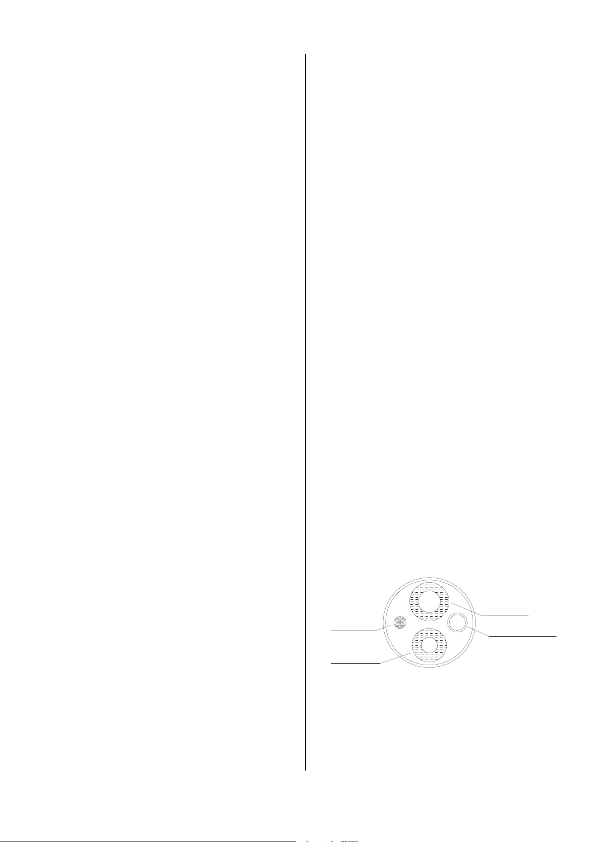
Wall lead-throughs
Wall lead-throughs are necessary to establish the connection between the indoor unit and the outdoor part.
Please observe the following:
à For the connection line to the outdoor part, a lead-
through of at least 70 mm in diameter must be created.
à The lead-through must be placed at an incline of at
least 10 mm from the inside to the outside.
à Before beginning work, make sure that there are no
supply lines (water, etc.) located in the vicinity of the
wall lead-through.
à We recommend cushioning the inside of the hole or
lining it with a PVC pipe to prevent the lines from being damaged.
à The indoor unit and outdoor part of the REMKO air-
conditioner have been adjusted to one another from
a technical standpoint.
The guarantee becomes null and void if third-party
components are used.
à Remember that when installing and maintaining air
conditioners, high-pressure refrigerant lines and
electrical current can pose hazards.
à During unit operation, some components in the cold
cycle can reach temperatures of more than 70 °C.
Be especially careful when covers are removed.
à The air intake and outlet openings may not be
blocked by furniture, curtains, etc.
à The refrigerant lines may not be bent or pressed.
Refrigerant
intake line
Control line
Refrigerant
injection line
à After assembly is complete, the wall lead-through
Condensation line
Wall lead-through diagram
must be sealed with a suitable sealing compound.
Do not use any materials containing cement or lime!
11
Page 12
Installation
Make absolutely sure to follow the instructions below
prior to assembling the indoor unit:
à When assembling the indoor unit, make sure that the
required minimum distances are observed.
Attaching the wall mount
The unit wall mounts are attached with screws and dowels suitable for attachment.
RKV 10 W / 13 W / 18 W
à Assemble the indoor unit in such a way that conden-
sation drainage is not blocked and air can always
flow freely in and out of the unit.
à The indoor unit is attached by means of a wall
mount.
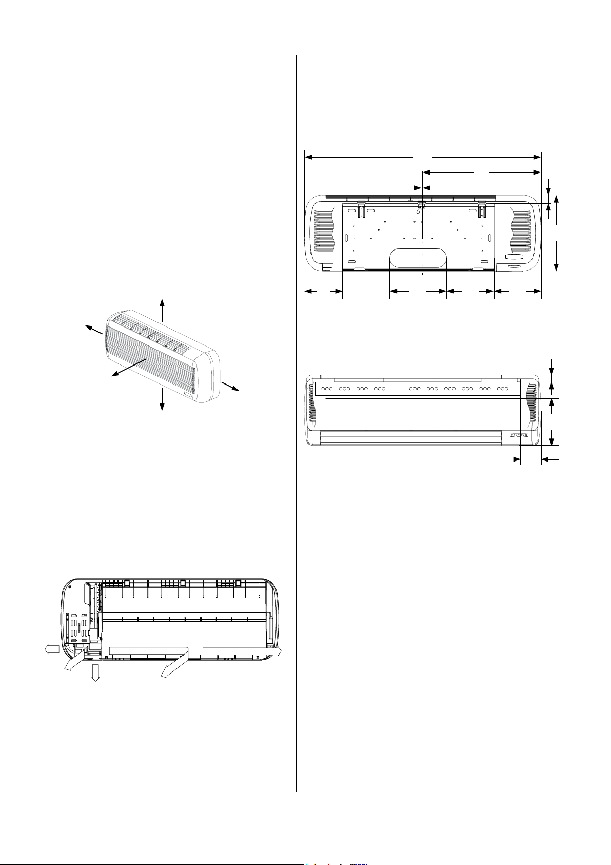
Minimum distances for the indoor units
The figure below shows the required distances to ensure
that the indoor units function properly.
120
120
1500
120
120
Dimensions in mm
These safety zones ensure that air can flow freely in
and out of the unit, that maintenance and repair work
can be performed and to protect the unit from damage.
160
RKV 24 W
1000
500
5
240 200 200
midddle of the unit
Front view, all specifications in mm
107
Front view, all specifications in mm
35
320
36
240
Lead-through options
Prior to installation, take a look at the various options for
lead-throughs of the refrigerant, condensation and control lines (see figure below).
1
5
2
3
1 Outflow on the wall right 2 Outflow through the wall right
3 Outflow on the wall bottom 4 Outflow through the wall middle
5 Outflow on the wall left
4
Units RKV 10 W, RKV 13 W and RKV 18 W can be
connected using all five options while the RKV 24 W
units can only be connected using options 1 to 3.
Assembling the indoor unit
Installation is performed as follows:
1. The required line cross-sections are provided in the
"Technical Data” table.
Only use refrigerant lines with refrigerator quality.
2. Decide on a drainage option for the indoor unit and
cut the refrigerant connection line hose accordingly.
3. When assembling the unit, observe the bending radii
of the refrigerant lines and never bend the hose in
the same place twice.
This may cause the line to become brittle or crack
4. Remove the preinstalled swivel nuts of the units.
5. Keep in mind that the indoor units have been filled
with dry nitrogen as a sealant at the factory.
The pressurised nitrogen is released when the
swivel nuts are loosened.
Only use the swivel nuts supplied for further assembly
.
12
Page 13
6. Use only the tools below for assembly. 15. If you have selected Option 2 or 4 (drainage through
the wall), guide the condensation water and control
line through the wall lead-through to the indoor unit.
If you also need a condensation pump, it must be installed beforehand.
16. If, due to structural design conditions, it is not possible to guide the condensation line through as well,
make sure that the condensation can drain freely at
all times.
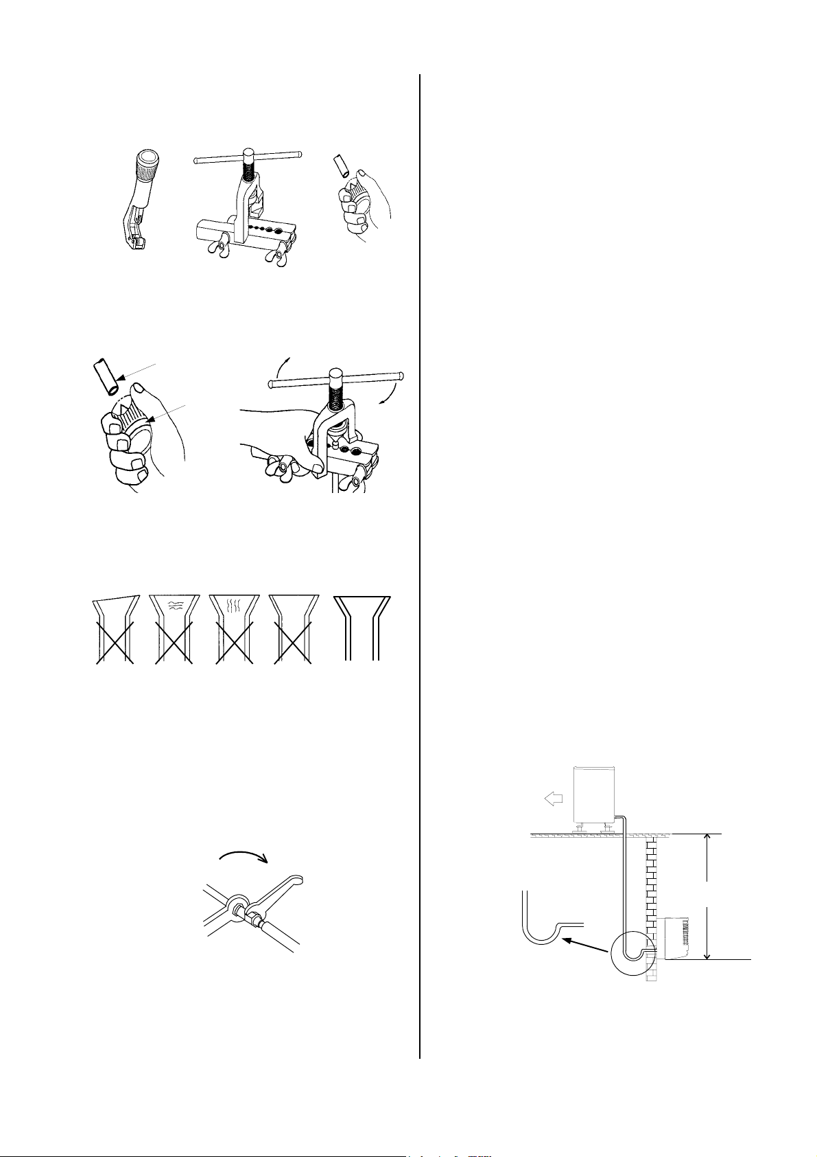
7. Before you flare the refrigerant lines, ensure that
there is a swivel nut on the hose.
8. Work with the refrigerant lines as shown in the figure
below.
Refrigerant line
Flare tool
17. Hang the indoor unit leaning slightly to the back in
the previously assembled wall mount and press the
bottom of the unit into the mount.
18. Lay the refrigerant lines from the indoor unit to the
outdoor part.
19. Make sure that the refrigerant lines are adequately
secured.
Deburrer
20. Take steps, if necessary, to ensure oil recirculation
as described in the section on oil recirculation.
21. Place the control line in the same line guideway.
22. Remove the protective caps supplied and the swivel
nut caps of the shut-off valves and use these for
continued assembly.
Only tools approved for use in cold conditions may
be used.
9. Make sure that the flare has the correct shape.
23. Connect the refrigerant lines to the outdoor part as
described above.
If the length of the connection line is longer than 5
m, refrigerant must be added to the system during
initial operation.
See the section Adding Refrigerant.
rippled
formation
of cracks
formation
of cracks
uneven
thickness
CORRECT
10. First manually connect the refrigerant lines with the
shut-off valves and the bolts to ensure that they are
in the proper position.
11. Now tighten the bolts using 2 open-end wrenches
that have a large enough opening.
12. Use a second wrench to apply counterpressure
when tightening.
Counterpressure
open-end wrench 2
Counterpressure
open-end wrench 1
13. Insulate the installed refrigerant lines including the
connector against heat.
14. Only use insulation hoses sealed against diffusion
that are suitable for this temperature range.
Oil recirculation
If the outdoor part is set up at a higher level than the indoor unit, appropriate steps must be taken for oil recirculation.
Outdoor part
Oil elevation arc in the
suction line to the outdoor
part 1x for every 2.5 m
Radius:
50 mm
maximum
10 m
Indoor unit
This is usually accomplished by creating an oil elevation
arc that is installed every 2.5 meters of line going up.
13
Page 14
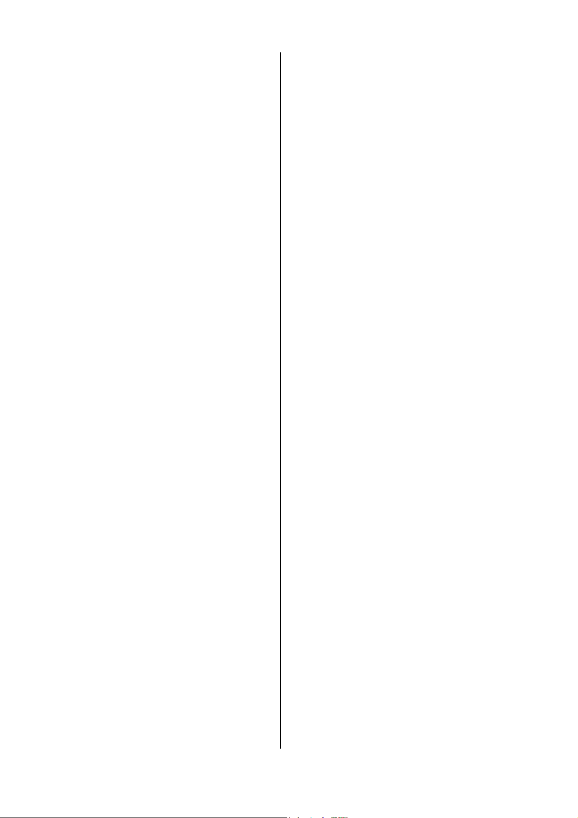
Impermeability Check
Once all connections have been made, the manometer
station is connected to the corresponding valve connections as described below:
red = small valve = injection pressure.
blue = large valve = suction pressure.
After the connection has been made, an impermeability
test is conducted using dry nitrogen.
The connections that have been established are
sprayed with a leak locator spray to test for impermeability. Tighten the bolts more firmly or, if necessary,
create a new flare.
After this test has been successfully conducted, any excess pressure is removed from the refrigerant lines and
a vacuum pump with an absolute final partial pressure
of at least 0.01 mbar is put into operation to create a
vacuum in the lines. This also removes any moisture
from the lines.
A vacuum with a minimum of 0.05 mbar must be
created!
How long it takes to create the vacuum is based on the
hose line volume of the indoor unit and the length of the
refrigerant lines. However, this process takes a minimum of 30 minutes.
Once foreign gases and moisture have been completely
removed from the system, the manometer station
valves are closed and the valves of the outdoor part are
opened as described in the section "Initial Operation“.
Adding Refrigerant
The refrigerant required for operating the system is located in the outdoor part.
For refrigerant lines longer than 5 m per cycle, refrigerant must be added in line with the information in the operating instructions for the respective outer part. Proceed as follows to add additional refrigerant:
Electrical Connection
A 4-wire control line must be led from the indoor unit to
the outdoor part. All electrical installations may only be
performed by authorised personnel in line with the relevant regulations.
Local guidelines for operation as well as the requirements established by local energy supply companies
must be observed for setup and initial operation.
Prior to performing any work on the unit, it must be
unplugged from the power supply and secured
against being inadvertently switched on!
Please observe the following:
à We recommend that the customer install a main or
repair switch close to the outdoor part.
à Power is supplied to the indoor units via a connec-
tion line from the outdoor part.
à Fuse protection for the system must occur in accor-
dance with the technical data.
à The electrical terminals of the connections are lo-
cated on the lower right hand side of the indoor unit.
Connecting the RKV 10 W, 13 W and 18 W units
Proceed as follows to connect the units:
1. Open the front of the unit and remove both filters.
2. Using a Phillips screwdriver, loosen both screws of
the grille mount and remove the grille.
3. Remove the six screws on the front of the housing.
4. Remember that three of the screws are hidden under caps behind the oscillating blades.
5. Remove the front cover of the housing.
6. Pull the terminal strip of the connection towards you
out of the unit.
7. Connect the unit to the current-free line from the
outer part.
See figures.
8. Reassemble the unit.
1. Remove the vacuum pump and connect the filling
cylinder.
2. Place the open cylinder on a scale and calibrate the
scale to zero.
3. Create a vacuum in the hose at the height of the manometer distribution pipe.
4. Determine the required amount based on the information in the operating instructions of the outdoor
part.
5. Open the suction pressure side of the manometer.
6. Close the manometer valve when the appropriate
amount has been added.
14
Connecting the RKV 24 W unit
Proceed as follows to connect the unit:
1. Open the front of the unit and remove both filters.
2. Using a Phillips screwdriver, loosen both screws of
the grille mount and remove the grille.
3. Remove the five screws on the right half-shell on the
housing.
4. Remove the half-shell to free up the control unit on
the right side.
5. Pull the terminal strip of the connection towards you
out of the unit
Page 15
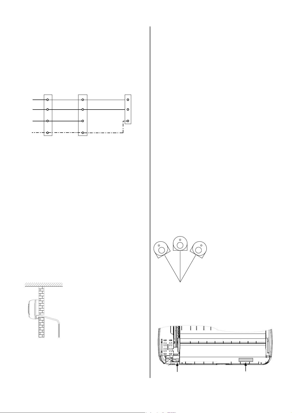
6. Connect the unit to the current-free line from the outdoor part.
See figures.
7. Reassemble the unit.
Electrical connection of the units:
Terminal strip
indoor unit
Red
White
Orange
YellowGreen
Terminal strip
outdoor part
A
N
Control
2
conductor
PE PE
A
N
2
Outer conductor
Neutral conductor
To the compressor
contactor
Protective conductor
Terminal strip
power supply
L1
230 V~,
50 Hz,
N
L1
N
PE
PE
External Condensation Pump
The condensation pump which can be purchased as an
accessory (Ref. no. 1613167) transfers the condensation which accumulates in the indoor unit to drains that
are placed in inconvenient locations, even if the drain is
located above the unit. The pump can be installed inside the unit.
Follow the operating instructions for the pump as well as
the instructions below:
à Protect the housing from coming into direct contact
with the condensation.
à Never open the housing of the pump.
à Check the operating current of the pump and the
power supply for consistency.
à Use the alarm contact to switch off the outdoor part.
à Keep in mind that you should only use the alarm
contact together with a contactor or relay to switch
off the outdoor part, depending on the load.
à Connect the pump securely to the control line.
Condensation Connection
Condensation forms on the plate fin exchanger of the
indoor unit during cooling operation because temperatures below the dew point are reached.
The indoor unit is equipped with a collection tray and a
condensation hose for the condensation that accumulates.
Follow the instructions below to lay the condensation
hose:
à The condensation drainage line is generally placed in
the same guideway as the refrigerant lines.
à If, as a result of structural design conditions, it is
necessary to have a different guideway for the condensation hose, the hose can also be guided to the
indoor unit through a different drain.
à If the unit is being operated at outside temperatures
below 0°C, the lines must be placed in such a way
that they are protected from frost.
à Make sure there is an adequate
incline for drainage.
It must be at least 2 %!
2 % incline
à If the supplied condensation
hose is not long enough, it can
be attached to standard hoses
with a 17 mm inner diameter.
The condensation pump consists of 2 components:
à The reservoir with sensor
à The pump
Reservoir with sensor
The reservoir collects the condensation. A sensor
switches the pump on when a specific water level has
been reached.
The electronic sensor allows the reservoir to be rotated
by up to 30° on its axis.
Possible assembly positions:
Rotation of the axis up to 30°
to the right and left.
Pump
The pump is attached to the right side of the unit (seen
from the back) using the supplied, self-adhesive strips.
à Always use suitable hose clips.
à If the condensation is being guided to a drainage
line, please install a siphon-like hose guideway which
acts as an odour seal.
à After the hose has been laid, check to make sure
that condensation can drain freely.
Reservoir Pump
15
Page 16
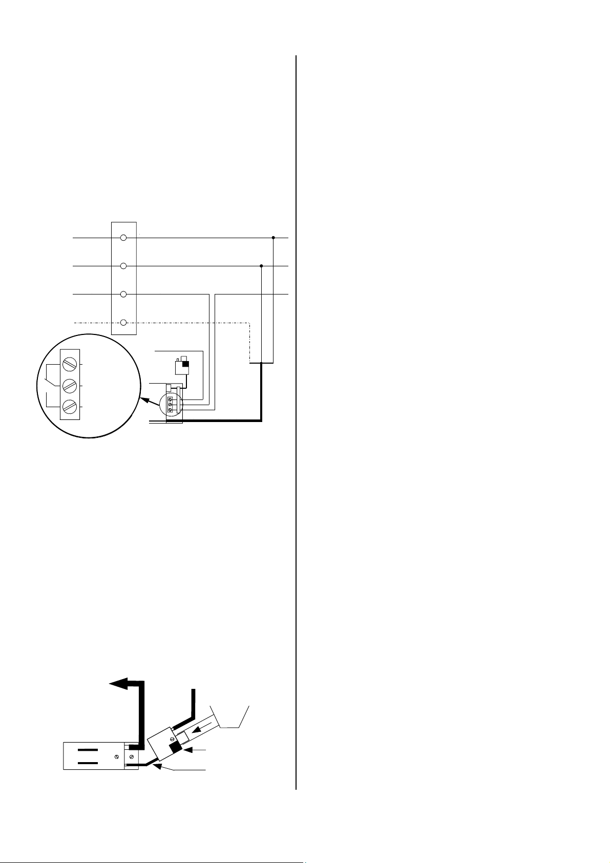
Electrical connection of the condensation pump
S
S
f
Entlüf
h
(l
)
The electrical connections may only be made by authorised service personnel in accordance with the relevant
regulations.
Prior to performing any work on the unit, it must be
unplugged from the power supply and secured
against being inadvertently switched on!
There is an electrical connection area located under the
hose connections. This area also a cover that can be
taken on and off.
Indoor unit
Innengerät
A
Red
Rot
White
Wei ß
Orange
Orange
Yellow-green
Gelb-Grün
Malfunction
Störung /
Alarm
/Alarm
Control conduct.
teuerleiter
indoor unit
Innengerät
Control conduct.
teuerleiter
Außenteil
outdoor part
Outer conductor
Außenleiter
N
Neutral conductor
Neutralleiter
Control conductor
Steuerleiter
2
indoor unit
Innengerät
PE
Protective conductor
Schutzleiter
Pump
Pumpe
Malfunction
Störung
Permanently wired
power supply line
Netzzuleitung
Control conduct.
Steuerleiter
outdoor part
Außenteil
est verdrahtete
Gelb-Grün
Blau
Braun
Blue
Brown
Yellow-green
The pump is equipped with an alarm contact that
switches off the indoor unit and can also control a customer-installed malfunction/alarm system.
Connections of the condensation pump on the water side
The reservoir is attached to the condensation collection
tray connection of the indoor unit via a customersupplied hose (20 mm Ø). The factory-installed flexible
hose of the condensation tray must be disassembled.
The reservoir and pump are connected to one another
with the long suction hose and the pluggable sensor line
from the reservoir. To ensure that the pump operates as
quietly as possible, the suction hose should not be
shortened.
The supplied ventilation hose must be used for the reservoir to function properly. The end of the ventilation
hose must at least be at the same height as the condensation tray to prevent water from overflowing.
The supplied metal wire clips are used to secure the
hose in a vertical position. Keep the hose from being
suspended which will prevent an air pocket from forming.
The 6 mm (inner diameter) thick hose is placed at a
maximum height difference of 6 meters to the drain.
The condensation line should be as vertical as possible
to guide the condensation.
If the pump is installed outside the unit, a maximum height difference of 3 m between the lower
edge of the unit and the pump mounted above
may not be exceeded
.
Initial operation of the condensation pump
Before putting the pump into operation, the lines that
have been laid must be checked to ensure that they are
functioning properly and leakproof.
1. Switch the power supply of the pump on.
2. Pour distilled water into the condensation tray until
the pump switches on from the reservoir.
3. Pump operation can be heard when it is being operated for the first time or being put back into operation.
After it has run for short period, the noise normalises.
4. Keep in mind that the pump automatically switches
off once the water has been pumped out of the reservoir.
5. If, upon initial operation, there is a lot of noise from
vibrating hoses, insulate these hoses using foam
hoses.
Condensation buildup is prevented when using insulated hoses sealed against diffusion.
6. Check the function of the alarm contact by drastically
increasing the amount of water.
The alarm contact should switch off the unit.
Kondensatab-
Condensation
laufschlauch
drainage hose
Pumpe
16
Pump
Ventilation house
tungsschlauc
(short)
(kurz)
Collection tray
Trop fw an ne
Reservoir
Reservoir
Ansaugschlauch
Suction hose
ang
(long)
Page 17
Prior to Initial Operation
After the pressure check has been performed, the vacuum pump must be connected to the valve connections
of the outdoor part (see section “Impermeability Check”)
by means of the manometer station and a vacuum created.
Prior to initial operation of the unit and after contact with
the cold cycle, the following checks must be performed
and documented in the initial operation log:
à Check all refrigerant lines and shut-off valves for
leaks with a leak locator spray or soapy water.
When the unit is not in operation.
à Check the connection lines to make sure that intake
and outlet lines have not been mistakenly switched.
à Check the refrigerant lines and the insulation for
damage.
à Check that the electrical connection between the in-
door unit and the outdoor part has the correct polarity.
à Check all fixtures and suspended parts to ensure
that they are in the proper position and at the correct
height.
à Check the surface temperature of the suction line
and determine the evaporator overheating.
To measure the temperature, hold the thermometer on
the suction line and subtract the boiling point temperature recorded on the manometer from the measured
temperature.
Before starting the test runs, follow the instructions below:
1. Remove the caps from the valves.
2. To begin initial operation, briefly open the shut-off
valves until the manometer displays pressure measuring approx. 2 bar.
3. Check the impermeability of all established connections with a leak locator spray or suitable devices.
4. If you did not find any leaks, open the shut-off valves
by turning them all the way counter-clockwise with a
hexagonal wrench.
5. If you found leaks, the connection must be reestablished.
It is absolutely necessary to create a new vacuum
and dry the unit!
If the refrigerant line is longer than 5 m, more refrigerant should be added to the system
.
Initial Operation
Once all components have been connected and
checked, the unit can be put into operation. Initial operation must performed using the certificate and must be
documented.
Following initial operation, the operator must be trained
in its operation and the initial operation log given to him.
Functional check and test run
To ensure that the unit is functioning properly, a functional check must be performed to identify any irregularities during unit operation before the unit is handed over
to the operator.
This check is dependent on the installed outdoor part.
These procedures are documented in the operating instructions of the outdoor part in use.
Cooling operation test run
Perform a test run for cooling operation as follows:
1. Switch the customer-installed main switch or fuse on.
2. Adjust the target temperature on the indoor unit to a
lower value than the existing room temperature using the remote control.
3. Switch the unit to cooling mode with the remote control.
The compressor starts a couple of minutes later
due to the delayed start.
4. Check that cold air is being expelled from the indoor
unit and warm air from the outdoor part.
5. During the test run, check all regulating, control and
safety mechanisms to ensure that they are functioning and set properly.
6. Check the indoor unit’s control mechanisms using
the functions described in the operating instructions.
Timer, temperature settings, fan mode and dehumidifying mode as well as all other mode settings.
7. Measure overheating, outside, inside, outlet and
evaporation temperatures and enter these values in
the initial operation log.
The functional tests are started via the indoor unit.
The following must be checked:
à Check refrigerant lines for leaks.
à Check that the fan and compressor are running
smoothly.
à Conduct a functional test of the indoor unit and all
program processes.
Completing initial operation
1. Remove the manometer and reattach all parts that
were removed.
Make sure that there are seals in the closing caps.
2. Complete the certificate for initial operation.
3. Familiarise the operator with the system and give
him the filled out certificate for initial operation.
17
Page 18
Environment and
A
-
Customer Service and
Recycling
Important information about recycling!
Only authorised personnel may come into contact with
the cold cycle. This ensures that refrigerant does not escape into the environment when the unit is being repaired. Both the refrigerant and the system parts are
subject to special requirements for disposal.
The refrigerant in use is a safety refrigerant. This means
that, should damage occur, the quantities released will
not cause injury to the respiratory systems of people
and animals.
Do not touch the liquid refrigerant as it can freeze the
skin!
Guarantee
For the guarantee to be valid, the purchaser or his customer must completely fill out the "guarantee certificate"
enclosed with all units and send it back to REMKO GmbH
& Co. KG
The units are repeatedly tested at the production site to
ensure that they are working properly. If a malfunction
occurs that cannot be eliminated by the operating personnel, please contact your dealer or contact person.
Proper use
The indoor units have been designed and fitted exclusively for operation with REMKO outdoor parts belonging to the RKV and RKM series.
The manufacturer assumes no liability for damage resulting from non-compliance with manufacturer specifications and legal requirements, or if modifications are
made to the units.
.
Operation/handling which does not comply with
these instructions is prohibited!
In cases of non-compliance, we assume no liability
and the guarantee becomes null and void.
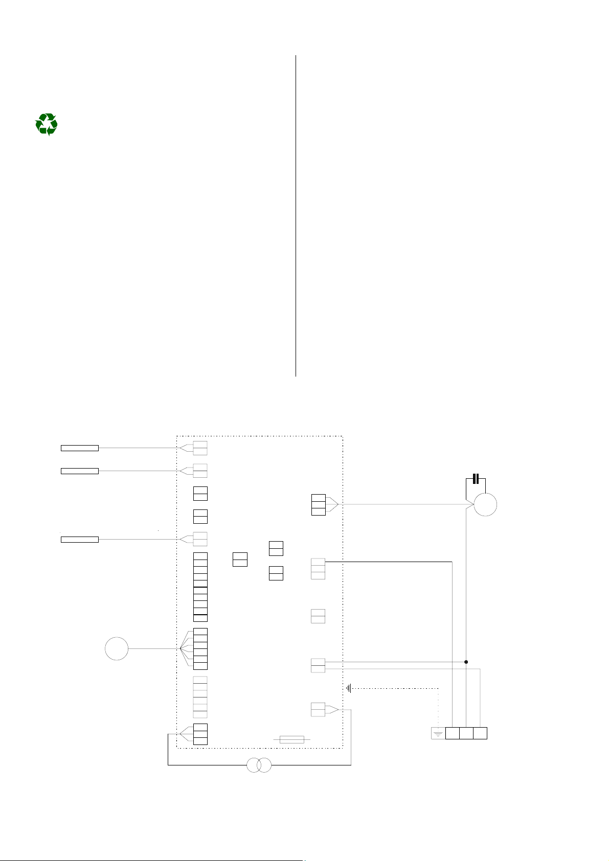
Internal Wiring Diagram
RKV 10 W, RKV 13 W, RKV 18 W, RKV 24 W
Circulation sensor
Sensor Umluft
Frost protection sensor
Sensor Einfrierschutz
Reed contact
Reed Kontakt
Air intake grille
nsauggitter
Swingmotor
Oscillating motor
(if available)
(falls vorhanden)
M
P1
TEMP
P2
FIN
P3
ODF
P4
P5
Door
P6 JP3
P7
STEP 2
P8
JP1
JP2
Condenser
Kondensator
ge
J1
FL
bl
FM
sw
FH
CP = Compressor
or
J2
J3
J4
CP
RV
OF
ws
rt
CP = Kompress or
ge = yellow
bl = blue
sw = black
or = orange
ws = white
rt = red
M
Ventilator
Fan motor
motor
STEP 1
P9
12-0-12
Transformator
Compressor
We reserve the right to make changes to dimensions and design in the interest of technical progress..
Fuse 3 A
Sicherung
J5
Terminal strip
A = Outer conductor
N = Neutral conductor
2 = Control conductor (compressor contactor)
2 N A
Klemmleiste
18
Page 19
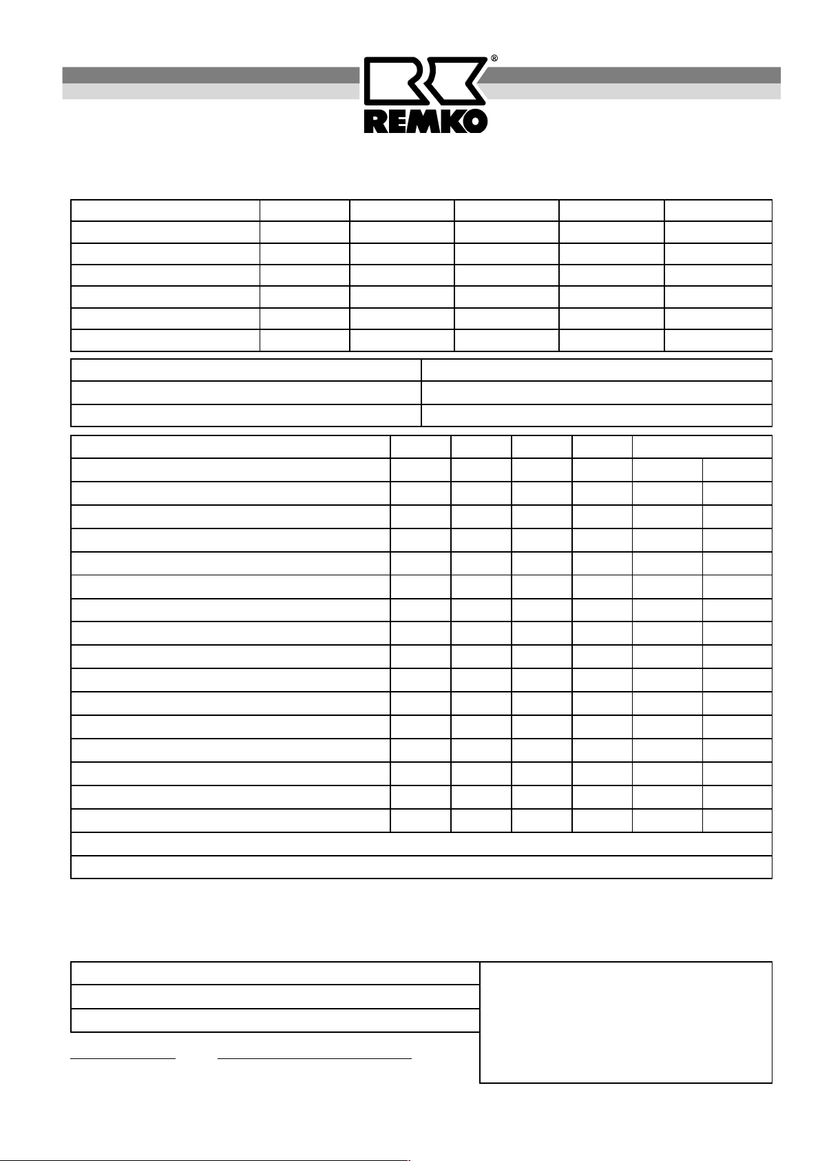
Certification for Date 01/2003
Initial operation Subsequent operation of a REMKO air-conditioning system
Unit data
Type of unit
Unit number
Refrigerant line length/height
Oil elevation arcs
Additional amount
Condensation pump
Operator / Setup location
Street: Postal code, city:
Telephone: Fax:
Outdoor part Indoor unit A Indoor unit B Indoor unit C Indoor unit D
RKV RKV RKV RKV
———– m/ m m/ m m/ m m/ m
———– units units units units
———– g g g g
———–
Name:
Testing of cycles A B C D Result
Visible check: Setup of outdoor part and indoor unit
Heat-exchanger, insulation, lines
Electrical fuse protection type A
Electrical power/control line (Cu mm²/mm²)
Impermeability check: Vacuum mbar
Excess pressure mbar
Add. preparation: Refrigerant refill amount g
Shut-off valves open
Functional test: Condensation flow, condensation pump(s)
Cooling mode
Heating mode (only for cooling/heating units)
Remote control
Operational check: Compressor
Fan mode
Measurement tests: Room temp. / Air outlet temp. °C / °C
Suction temp. / Overheating °C / K
Comments:
/ / / /
/ / / /
/ / / /
R good Q poor
R good Q poor
R good Q poor
R good Q poor
R good Q poor
R good Q poor
R good Q poor
R good Q poor
R good Q poor
R good Q poor
R good Q poor
R good Q poor
R good Q poor
R good Q poor
R good Q poor
R good Q poor
The room air conditioning system above was put into operation without any objections.
The operator has been trained and the operating instructions distributed.
The unit could not be put into operation for the reasons indicated above.
Executing company:
Company:
Street:
Postal code, city:
Date Operator signature
Stamp and signature
Signature of person assembling / putting unit into operation
19
Page 20

REMKO GmbH & Co. KG
Klima- und Wärmetechnik
D-32791 Lage • Im Seelenkamp 12
D-32777 Lage • PO Box 1827
Phone +49 (5232) 606 - 0
Fax +49 (5232) 606260
E-Mail: [email protected]
Internet: www.remko.de
 Loading...