

Remington IM 812-2 Installation & Maintenance Data
Installation & Maintenance Data IM 812-2
McQuay/Remington
Packaged Terminal Air Conditioners and Heat Pumps – C Vintage
Group: PTAC/PTHP
Date: April 2006
®
©2006 McQuay International
Table of Contents
General Description ............................................................ 2
Warning ............................................................................... 2
Inspection ........................................................................... 2
Nomenclature...................................................................... 3
Control Features .............................................................. 4-5
Wall Opening Requirements and Unit Dimensions ............. 6
Installation of Optional Condensate Drain Kit ..................... 7
Subbase Installation............................................................ 8
Power Supply and Control Wiring....................................... 8
Wall Sleeve Installation
Thin Wall Construction ................................................. 9
Medium Thick Wall Construction ............................... 10
General Description
McQuay®/Remington® Packaged Terminal Air Conditioners and
Heat Pumps are designed and built for through-the-wall
installation in either new or existing buildings. The self-contained refrigerant system delivers cooling to the desired space.
Heating can be accomplished with electric resistance or with
reverse cycle technology (heat pump models only). Generally,
an estimate for capacity selection is 35 BTUH per square foot
of floor space (cooling) and 4 BTUH (1.25 watts) per cubic
foot (heating). The architect or engineer must verify the selection. Note that the heat pump reverse cycle generates approximately 10 BTUs per electrical watt as compared to 3.4
BTUs per watt with resistance electric heat. The unit will restart at its last setting after a power interruption. A complete
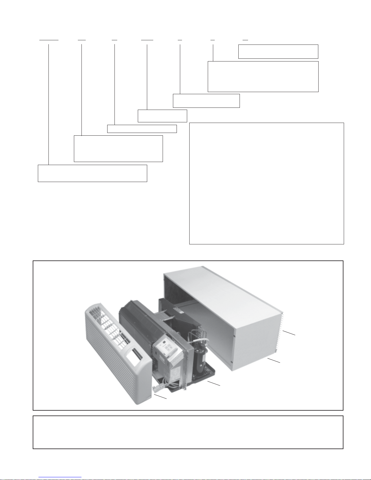
unit consists of the following components, ordered and
shipped separately.
1. Heating/Cooling Chassis and Front Panel.
2. Wall Sleeve.
3. Outdoor Louver.
4. Subbase – Optional for 208V and 230V units but mandatory for all 265V.
5. Separate plug-in power cord (selects heater size).
NOTE: Some units with fixed heaters are also available
with factory installed power cords.
6. Electrical receptacle – Optional for 208V and 230V units
but mandatory for all 265V.
7. Plug cord cover – Optional for 208V and 230V units but
mandatory for all 265V.
Thick Wall Construction ............................................. 11
Wall Sleeve Extension and Louver Frame......................... 12
Outdoor Louvers ............................................................... 13
Installation of Louvers and Chassis .................................. 14
Equipment Start-up .......................................................... 15
Remote Mounted Thermostat ........................................... 17
Wiring Diagrams........................................................... 18-20
Scheduled Maintenance ................................................... 21
Spare Parts ....................................................................... 21
Shipping Weights .............................................................. 22
Refrigeration Cycle ........................................................... 22
Trouble Shooting .......................................................... 23-25
NOTICE
This product was carefully packed and thoroughly
inspected before leaving the factory. Responsibility
for its safe delivery was assumed by the carrier upon
acceptance of the shipment. Claims for loss or damage
sustained in transit must therefore be made upon the
carrier, as follows:
VISIBLE LOSS OR DAMAGE
Any external evidence of loss or damage must be
noted on the freight bill or carrier’s receipt, and signed
by the carrier’s agent. Failure to adequately describe
such external evidence of loss or damage may result
in the carrier’s refusal to honor a damage claim. The
form required to file such a claim will be supplied by
the carrier.
CONCEALED LOSS OR DAMAGE
Concealed loss or damage means loss or damage
which does not become apparent until the product
has been unpacked. The contents may be damaged in
transit due to rough handling even though the carton
may not show external damages. When the damage is
discovered upon unpacking, make a written request
for inspection by the carrier’s agent within fifteen (15)
days of the delivery date. File a claim with the carrier
since such damage is the carrier’s responsibility.
WARNING
!
The installer must determine and follow all applicable
codes and regulations. This equipment presents hazards
of electricity, rotating parts, sharp edges, heat and weight.
Failure to read and follow these instructions can result in
property damage, severe personal injury or death. This
equipment must be installed by experienced, trained
personnel only.
CAUTION
!
Use copper conductors only. Unit terminals are not designed to accept other types of conductors.
Failure to do so can damage equipment.
IM 812 / Page 2 of 28
WARNING
!
Inspect unit nameplate to be certain the voltage is the
same as the voltage that will be delivered to the unit. The
receptacle must match the plug on the unit cord. Improper
electrical wiring can cause property damage, severe personal injury or death.
WARNING
!
Hazardous Voltage!
Disconnect all electric power including remote
disconnects before servicing. Failure to discon-
nect power before servicing can cause severe
personal injury or death.
Product Nomenclature
PTAC 07 C 208 F 3 C
▲
▲
▲
▲
▲
▲
0 = 0.0 kW No Electric Heat
2 = 2.4 Nominal kW Electric Heater
3 = 3.5 Nominal kW Electric Heater
5 = 5.0 Nominal kW (30A) Electric Heater
Z = 5.0 Nominal kW (20A/265V) Electric Heater
F = FixedCord Heat
U = Universal Cord Heat
2
3
208 = 208-230V
265 = 265V
C = “C” Design Vintage
07 = 7,000 Nominal BTUH Cooling
09 = 9,000 Nominal BTUH Cooling
12 = 12,000 Nominal BTUH Cooling
15 = 15,000 Nominal BTUH Cooling
Notes
1.
All chassis ship with an Installation Manual and mounting screws.
2. Factory-installed. Check notes 5 & 6 for availability.
3. Field-installed. Check notes 5 & 6 for availability.
4. Available on size 12 & 15 units only. Order Universal Power Cord
for “Cooling Only”.
5. Available with fixed cord for all 208-230V PTAC/PTHP size 07 &
PTAC = Packaged Terminal Air Conditioner
PTHP = Packaged Terminal Heat Pump
1
1
09 units and for 265V PTHP size 09. Available with universal
power cord for all PTAC/PTHP size 12 & 15.
6. Available with fixed power cord on all PTAC/PTHP units.
Available with universal power cord on all PTAC/PTHP size
12 & 15.
7. Universal power cord with 30A plug for PTAC/PTHP size
12 & 15 only.
8. Universal power cord with 20A plug for 265V PTAC/PTHP size
12 & 15 only.
9. Includes control pad and mounting frame.
10. Wall Mounting Kit & Control Pad or 24V Wall thermostat &
Control Blank Off must be ordered separately. See accessory
tables.
▲
C = Chassis Mounted Control
W =Wall Mounted Control
4
10
5
6
7
9
8
Figure 1. Exploded View of Complete Unit (Shown without subbase)
▲
Louver
▲
Wall Sleeve
▲
Chassis
▲
Front Panel
Now that you have made an investment in modern, efficient McQuay®/Remington® equipment, its care and
operation should be a high priority. For training information on all McQuay HVAC products, please visit us at
www.mcquay.com and click on Training or phone 540-248-0711 and ask for the Training Department.
IM 812 / Page 3 of 28
Control Features
Standard Control
Control Pad - Can be unit-mounted or can be remote wall
mounted. Remote mounting requires an accessory 35´ or 50´
low-voltage wire harness and snap-in decorative cover. The
mounting location must be away from cold drafts, discharge
air, outside walls, etc., because the room temperature sensor
is mounted in the control pad (if dip switch #2 of 4, behind the
access cover on front of the control box, is “ON”). A wireless
hand-held remote controller is also available as an accessory,
which allows control of the conditioner from anywhere in the
room.
Heat – Select by pressing the ON/OFF key to “ON” and the
+
왕
MODE key to “HEAT.” Use the
room temperature (60-85OF).
NOTE: Heat pumps will not operate in reverse cycle unless temperature setting is within 2
ture. Otherwise, unit will heat with electric heaters until
satisfied. The next call for heat will be reverse cycle, provided the outdoor temperature is above the 30-40
When the outdoor temperature is less than 25
the heating will be with electric resistance. Between 25oF
and 40oF, the primary heat will be reverse cycle with occasional resistance heat as required to maintain room temperature. Above 40
o
F, all heating will be by reverse cycle.
Cool – Select by pressing the ON/OFF key to “ON” and the
MODE key to “COOL.” Use the
room temperature (60-85OF).
Fan Only – Select by pressing the ON/OFF key to “ON” and
the MODE key to “FAN”. Press the FAN key to select high or
low speed. In this mode, only the indoor fan will operate and
there will be no heating or cooling.
Cool/Dry – Press the ON/OFF key to “ON” and the MODE key
to “COOL”. Press and hold the MODE key for 15 seconds to
activate “COOL/DRY”. Use the
room temperature. Select this mode when the standard Cool
mode does not provide sufficient dehumidification. The compressor and indoor low fan will cycle together and will operate
for longer periods of time to provide up to 70% more dehumidification. As a result, the room temperature differential may
increase slightly.
NOTE: COOL/DRY can not be used with SLEEP.
Fan Speed – Select fan speed by pressing the FAN key to
“AUTO”, “HIGH” or “LOW” while the unit is operating in
“HEAT”, or “COOL” mode. “AUTO” gives high fan if unit setting is more than 2
low fan if less than 2
Continuous/Cycle Fan – When dip switch #8, located on front
of the control box, behind the access cover, is in the “OFF”
position, the indoor fan will operate continuously. When dip
switch #8 is in the “ON” position, the indoor fan will cycle on
and off with the compressor or heater. In cycle fan, (dip switch
#8 “ON”) the fan will start every 7 minutes to sample the room
temperature. Fan will turn off again after 2 minutes unless heating or cooling is required.
IM 812 / Page 4 of 28
o
F above or below room temperature and
o
F above or below room temperature.
or 왓- key to set the desired
o
F of room tempera-
o
F range.
o
F, most of
+
왕
or 왓- key to set the desired
왕+ or 왓- key to set the desired
Room Freeze Protection
– When dip switch #4 of 4 (located
behind the access cover on front of the control box) is "OFF",
a unit-mounted sensor will be activated to bring on the elec-
o
tric heater and indoor fan as required to maintain a 40
-50oF
minimum temperature. This will override “OFF”, remote “OFF”,
“COOL”, “COOL/DRY”, “FAN” and “UNOCCUPIED” modes.
When dip switch #4 of 4 is “ON”, there is no freeze protection.
Also, if using a 24V wall stat, there is no freeze protection (unless provided by the wall stat).
IMPORTANT NOTE: When dip switch #4 of 4 is "ON", there
is no freeze protection.
CAUTION
!
Absence of freeze protection can result in equipment and
property damage. Make certain dip switch #4 of 4 is “OFF”,
if freeze protection is required.
Wired Remote ON/OFF
– The unit may be turned on by open-
ing, or off by closing, a set of dry contacts located up to 325´
from the unit using a pair of 22 ga. low voltage wires. The 22
ga. wires are connected to the unit using a plug and receptacle connection under the small access cover on the front of
the control box. (A plug with 2 short wires is shipped with the
chassis and plugs into “F. DESK” receptacle) The dry contacts can be a toggle switch at the front desk, a time clock,
etc. When the dry contact is closed, the unit control goes to
o
memory P1 which is set from the factory at 75
F in COOL
mode and high fan. If desired, P1 can be programmed for a
different setting. See instructions under “Motion Sensor & Door
Switch”, page 5. When the dry contact is opened and the unit
restarts, the control will automatically index to a Heat setting
o
F (if room temperature is below 68oF) or a Cool setting of
of 68
o
F (if the room temperature is above 68oF. )
75
NOTE: If the unit has been turned OFF by remote dry contacts and the room occupant presses the ON/OFF key on
the control pad, the indicator lights will come on and the
control will start beeping but the unit will not heat or cool.
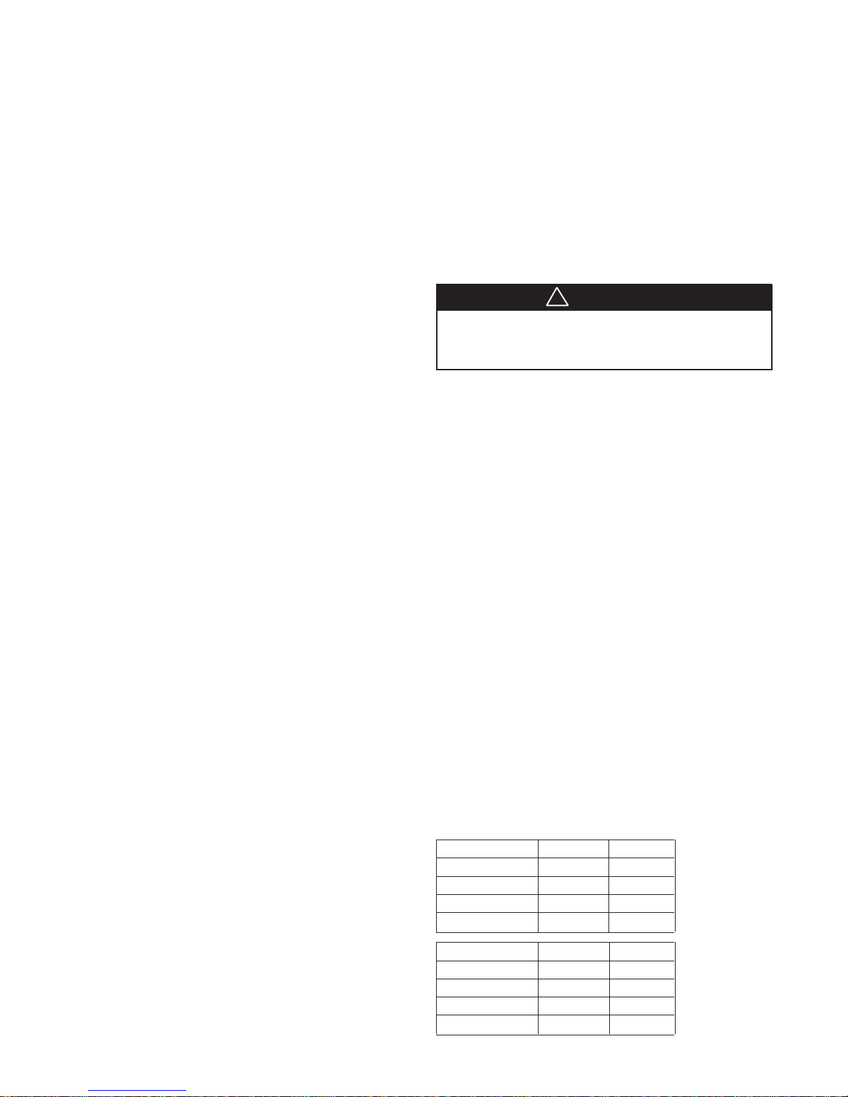
Temperature Limiting
– The control temperature range as
shipped from the factory is from 60o-85oF. By using dip switches
#1-#4 of 8 (located behind the access cover on front of the
control box), the range can be changed per the following charts:
NOTE: After the limits have been set, the control display
o
will still show the full range of 60-85
F, however, the unit
will not heat or cool past the limits.
Min. Set Point SW #1 SW #2
60oF OFF OFF
64oFONOFF
68oF OFF ON
72oFONON
Max. Set Point SW #3 SW #4
75oFONON
78oF OFF ON
82oFONOFF
85oF OFF OFF

Dip Switch Description (located behind
access cover on front of control box)
Dip SWI #1–#8
#1–#4 = Temperature Limiting – see charts, page 4.
#5–#6 = Approximate outdoor temperature when unit will automatically change from reverse cycle heating to electric heat.
#5-OFF & #6-OFF = 35
#5-ON & #6-OFF = 30
#5-ON & #6-ON = 25
#7-OFF = Normal HP operation, ON = electric heat only.
#8-OFF = Constant indoor fan, ON = Cycle
Dip SW2 #1–#4
#1-OFF = Control pad activated, ON = 24V wall stat activated.
#2-OFF = Room temperature sensor on chassis, ON = sensor
on control pad.
#3-OFF = Motion & Door sw. activated, ON = Timer and Sleep
activated.
#4-OFF = Room freeze protection is activated, ON = deactivated.
NOTE: All dip switches ship from factory in the OFF position except #8 of 8 and #3 of 4 which are shipped turned
ON. Any switch changes must be followed by unplugging
and plugging in the power cord to activate the change.
Quick Heat & Cool
– This feature provides extra comfort for
the occupant during start up of an unconditioned space. When
off for more than 2 hours, the unit setting will automatically
o
F in Heat or drop 2oF in Cool to offset the radiation felt
raise 2
from the cold or warm walls, ceiling and floor. The 2oF offset is
maintained for the first cycle only. After that, the setting reverts to that shown on the digital display.
Motion Sensor & Door Switch – (activate by dip switch #3 of
4 turned OFF)
– Two receptacles under the access cover on
front of control box provide connections for the motion sensor and door switch. (Motion sensor and door switch are available from your sales representative. The motion sensor is custom-made for McQuay with both “ON” & “OFF” having no
time delay. Motion sensors by others will not work.) Two plug
and wire assemblies are included with each chassis. Connect
receptacle “MOTION” to motion sensor and “DOOR” to door
switch.
While room is occupied, the motion sensor keeps the control
“normal” so the occupant has full control of the unit. Fifteen
minutes after the occupant leaves the room, the unit goes into
memory P2. 14 hours later, if no one has entered the room,
the unit goes into memory P1. Both P1 and P2 come factory
set in COOL mode @ 75
temperature and mode by using a G11 hand held remote controller available from your sales representative.
o
F (factory setting)
o
F
o
F
o
F. They can be reprogrammed for
Programming P1 using the G11 control – press and hold
the upper + button for 3 seconds until P1 starts flashing on
the G11 display. While P1 is still flashing, press the buttons to
select temperature, fan speed, and mode for P1. Wait 15 seconds until P1 stops flashing, then press and release the upper
+ button to send the P1 program to the unit control. P1 will
flash on the unit display to show it was accepted.
Programming P2 using the G11 control – press and hold
the upper - button for 3 seconds until P2 starts flashing. While
P2 is still flashing, select temperature, fan speed, and mode
desired for P2. Wait 15 seconds until P2 has stopped flashing, then press and release the upper - button to send the P2
program to the unit control. P2 will flash on the unit display to
show it was accepted.
Control Lockout
– The unit control has an electrical lockout
feature to prevent anyone from changing the mode, temperature or fan speed. To activate this lockout, press and hold the
unit FAN key for 10 seconds until LO shows on display. To
unlock the control, press and hold the FAN key for 10 seconds until UL shows.
Remote Wall Thermostat
General – Remove the control pad from the unit by unsnap-
ping it from its base and unplugging it from the receptacle on
the control box front. The snap-in decorative cover (ordered
separately) now mounts in place of the control pad. To modify
the controls for Remote Wall Thermostat, slide dip switch #1
of 4 to ON. Also, unplug the power cord from the receptacle
and plug back in again to reset the circuit. Four to seven lowvoltage wires, as determined by the wall thermostat selected,
connect to the 7 pin receptacle CN2, behind the access cover,
on the control box front. Use the 7 pin plug and wire assembly
provided. Mount the thermostat on an inside wall. Avoid unit
discharge air, direct sunlight and cold drafts.
Operation
R, W, Y, and G terminals plus C if it requires 24V AC power
from the unit. By using all 7 low voltage connections, wall stats
with 2 stage heat & fan speed selection can also be used.
Stats can be MCO, ACO, MCO/ACO or programmable. With
the exception of “wired Remote ON/OFF”, the control features listed for the standard control pad will not be available
with the wall thermostat. Low fan speed is standard for stats
without speed selection.
– The 24V wall thermostat should have the normal
IM 812 / Page 5 of 28

NOTICE
Unit Installation – General
Wall Opening Requirements
Before installing the unit, check the wall opening to be sure
the wall sleeve will slide into the opening unobstructed. For
masonry walls, a lintel must be used to provide support over
each opening. The rough opening should measure 16
x 421⁄4˝ wide (see Figure 2, Note 2). When a subbase is used,
1
the opening must start 3
⁄4˝ or 41⁄4˝ above the finished floor to
match the height of the subbase selected. The subbase is
available in either a 3˝ or 4˝ height and is required for 265V but
is optional for 208/230V. Each subbase has leveling legs to
provide up to 1˝ additional height. When no subbase is used,
the opening can start right at the finished floor level (208/230V
only). Leave enough space for carpeting, etc.
Figure 2. Unit Dimensions
1
⁄4˝ high
Heat pump models will generate condensate during the
heating season. If it is not desirable for this condensate
to exit outdoors from the wall sleeve drain holes, install
indoor or outdoor drain kits, available from your sales
representative (see page 7).
3/8˝ (Stamped Louver)
11⁄8˝ (Architectural Louver)
42˝
133⁄4˝
16˝
Subbase
3
13
⁄4˝
See
Note 1
Side View
3
⁄4˝
20
7˝
Top View
7˝
42˝
16˝
1/2˝
41
1
⁄2˝
See Note 1
Front View
Notes:
1. Unit pictured with subbase installed. Subbase is optional on 208V/230V units but required on all 265V units. See pages 8, 9,
10, and 11 for subbase dimensions, and details.
2. Opening needs to be 165⁄8˝ x 42
5
⁄8˝ when using a louver frame. See page 12, Figure B.
IM 812 / Page 6 of 28
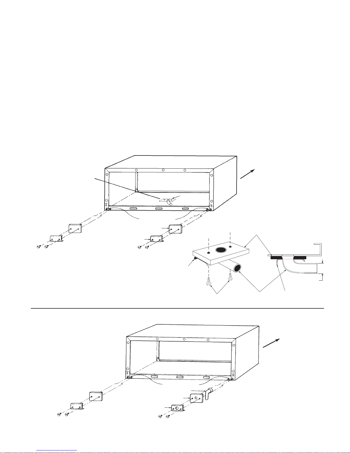
Installation of Optional Condensate Drain Kit
Figure 3 illustrates the installation of the indoor drain kit. The
indoor drain kit must be installed before placing the wall sleeve
into the opening. Install as follows:
1. Locate the drain so that it will be on the room side of the
wall when the wall sleeve is installed.
2. Drill a 1/2
˝ diameter hole in the base of the wall sleeve for
the drain.
3. Drill two (2)
5/32˝ pilot holes for the mounting screws.
These holes can be located using the drain kit as a
pattern.
4. Assemble the drain kit as shown in Figure 3 and securely
fasten it to the wall sleeve with the screws provided. Use
o
either the 90
elbow or 6" straight fitting as required.
5. Install the wall sleeve as described on pages 9, 10, or 11.
Figure 3. Indoor Drain Kit
Contractor to Drill
Three (3) Holes to
Accept Drain Kit
Assembly of the outdoor drain kit should be completed after
the wall sleeve has been installed.
Note: When using the outdoor drain kit, the sleeve
must be flush or beyond the outside finished wall
(do not recess).
Install the outdoor drain kit as follows:
1. Assemble the drain kit as shown in Figure 4.
2. Choose the side of the wall sleeve to which the drain kit
is to be installed.
3. There are drain holes and pilot holes provided in the wall
sleeve from factory. Place the drain kit against the chosen drain hole and fasten securely with screws provided.
Use either the 90
4. Cover the unused drain hole with the block off plate and
gasket supplied with the drain kit.
See Detail
Below
o
elbow or 6" straight fitting as required.
Indoor
Figure 4. Outdoor Drain Kit
Square Drain Holes
Neoprene Sponge Gasket
Block Off Plate
Neoprene Sponge Gasket
Steel Mounting Plate
Steel Mounting
Plate
Square Drain Holes
1
⁄2" O.D. Drain Tube
DETAIL
Screws
Gasket
Tube
Cabinet Bottom
Steel Mounting
Plate
Indoor
1
⁄2" O.D.
IM 812 / Page 7 of 28
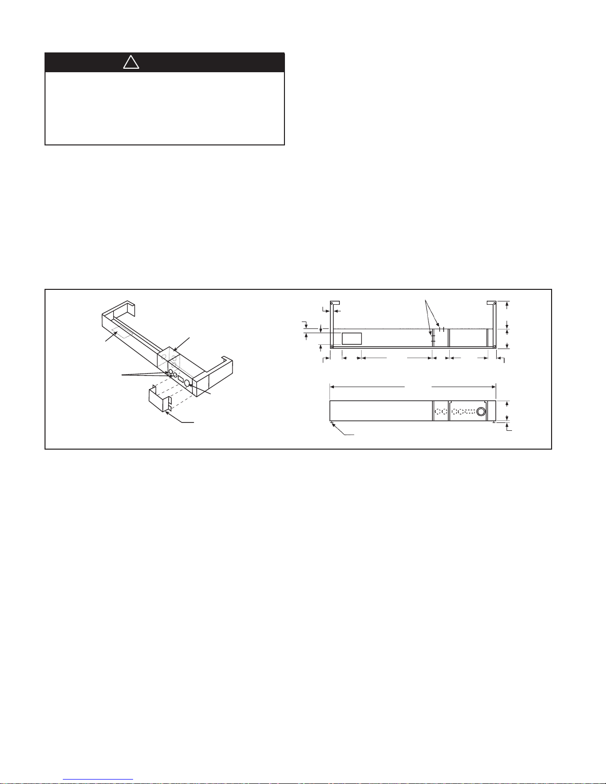
Subbase Installation
WARNING
!
All electrical work must be done by trained, experienced
electricians in accordance with applicable codes and standards. Kinked, bent or chaffed cords; improper grounding or fusing; improper current or voltage; or improper
installation can cause fire or electric hazards that can result in property damage, personal injury or death.
Electric Subbase
An electrical subbase is optional for 208V and 230V units, but
is standard for 265V units. It is available in two sizes: 3˝ or 4˝.
The subbase contains leveling legs for adjustment of up to 1˝
additional height. Install the wall sleeve and subbase at the
same time.
Note: A minimum of 4
into the room when using a subbase.
Figure 5. Electric Subbase
3" x 5"
Opening for
Electrical and/or
Drain Rough-In
Knockouts for
Optional Fuse &
Disconnect Switch
3
⁄8˝ of the wall sleeve must project
Electrical
Junction
Box for Main
Power Connection
Side
Extension
Piece
Receptacle
Mounting Location
Plug/Cord Cover
(Required on 265V Units Only)
Installation
1. If the minimum depth subbase is required (4
3
⁄8˝), discard
the side extension pieces. The subbase always mounts
flush with the front of the wall sleeve.
2. If more than the minimum depth subbase is required, determine the depth of the side extension pieces desired
and break at the proper score-line. Insert the side extension pieces into the front assembly and secure with two
short black screws at each side.
3. Insert leveling legs into subbase bottom flanges. Four (4)
legs will be needed if side extensions are used. Only two
(2) will be required if side extensions are not used.
4. Place the subbase on the floor and align its center line
with the center line of the wall opening. Do not fasten the
subbases to the floor. After the wall sleeve has been installed, attach the subbase to it using the two clips
provided. Adjust the subbase height so it rests tight against
the bottom of the wall sleeve.
5. The wiring should be roughed in and the conduit connected
to the electrical junction box. Complete the installation by
wiring the receptacle to the incoming power supply.
7
⁄8"
5
⁄8"
3"
21⁄2"
5"
Leveling Leg
Front Elevation (Three Front Panels in Place)
Electrical Knockouts
17"
31⁄2"
Plan
411⁄2"
0" to 93⁄8"
43⁄8"
12"
11⁄2"
3" or 4"
0" to 1"
Power Supply and Control Wiring
All wiring must be done in accordance with local and National
Electrical Code requirements. Some units have a multitap
heater, so the Kw is determined by the field-installed power
cord, and some have factory installed cords with fixed heaters. Refer to the data plate for proper overcurrent protection.
Time delay fuses or HACR circuit breakers are required to avoid
nuisance tripping.
Power Supply Wiring
208V and 230V units use a power cord that exits from beneath
the conditioner on the control (R.H.) side. The cord has a usable
length of 60˝ from where it exits the conditioner. (Do not use
extension cords.) When a subbase is not used, the receptacle
is generally mounted beneath the conditioner or on the wall
beside it (208-230V only). An electrical subbase is available
and contains a junction box for a field-mounted receptacle.
All electrical connections are made within the subbase, thus
eliminating the need for a wall-mounted receptacle (see Figure 5). The subbase is available in 3˝ or 4˝ height and can be
furnished with a factory-mounted fused disconnect and receptacle as an option. The subbase is optional for 208V and
230V, but mandatory for 265V. The 265V chassis uses a “short
cord,” which is just long enough to plug into the subbase. A
plug/cord cover is also required on 265V to make the power
cord inaccessible without the use of tools, (see Figure 5).
IM 812 / Page 8 of 28
Control Wiring
If the unit control pad will be wall mounted, rough in the 35´ or
50´ low-voltage wire harness at this time. The end of the harness, with exposed terminals (the larger black connector), will
plug into the control box at the unit. The other end (smaller
white connector), with concealed terminals, will connect to
the PC board in the control pad on the wall. At the unit, exit
the wall with enough wire harness to reach the CN5 receptacle behind the access cover on the control box front. At the
control pad mounting location on the wall, exit with only a few
inches of wire harness. Route the wire harness through the
opening in the control pad mounting plate and secure the plate
to the wall. Unplug the short cord from the PC board in the
control pad and discard. Plug in the new wire harness from
the wall and snap the control pad onto the mounting plate.
The harness should all be concealed behind the control pad
when finished. If an optional 24V wall stat will be used rather
than the control pad, rough in the 4 to 7 low voltage wires as
required by the stat. If remote ON/OFF control will be used,
rough in 2 low voltage wires (22 ga. min.) to a maximum of
325´ from the unit, (see page 4.) If unit will be connected to a
motion sensor and door switch, rough in the 4 low voltage
wires for the motion sensor and the 2 low voltage wires for the
door switch. Leave enough wire at the unit to reach the receptacles behind the access cover on front of control box.
Wall Sleeve Installation – Thin Wall Construction
For panel wall and thin wall construction, a louver frame may be used. Refer to page 11 for installation of louver frame before
continuing.
Panel wall and thin wall construction varies only slightly from
frame and brick construction. Note: The center of gravity is
1
⁄4˝ from the outdoor edge of the wall sleeve. The wall sleeve
10
must be supported to the center of gravity. Support can be
from a factory-supplied subbase or from other field-supplied
materials or it can be floor mounted for 208/230V.
WARNING
!
Failure to provide proper support can result in property
damage and severe personal injury.
Install as follows:
1. Clean the opening of all debris that may interfere with
installation.
2. If the unit is to be supplied with a subbase, refer to page
8 for installation procedure. (265V always requires a
subbase.) Install the subbase and wall sleeve at the
same time.
3. If the optional drain kit is to be employed (heat pumps
only), refer to page 7 before proceeding.
4. Recess the wall sleeve so that the louver is flush with the
outside of the building. (Do not recess if using the outdoor drain kit. See page 7.)
5. Level wall sleeve left to right, pitch it 1/4" bubble to the
outdoors and secure in wall with fasteners (as shown in
Figure C, page 12). A 5/16˝ hole is provided on each side,
2˝ down from the top and 2˝ in from the rear. Additional
holes may be required to firmly secure the wall sleeve.
CAUTION
!
Do not drill holes in the bottom of the wall sleeve as it
may cause leakage.
Where a subbase is used, secure the wall sleeve to the
subbase with the two clips provided (see subbase installation, page 8).
6. Be sure the wall sleeve is mechanically attached to the
wall for a proper seal. Use the louver frame for this purpose (see Figure B, page 12).
7. Caulk the wall sleeve to the wall opening on both the inside and outside perimeter. Be careful not to plug the weep
holes. Caulking should be a resilient, non-hardening type,
such as silicone.
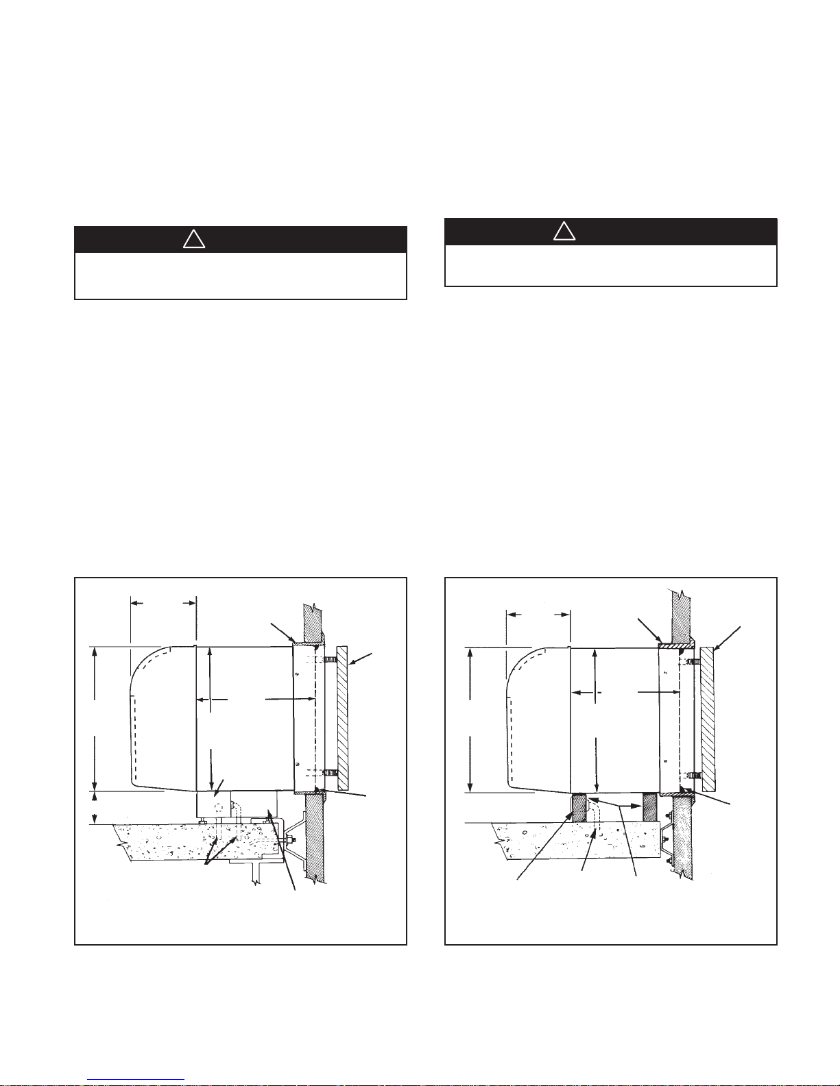
Figure 8. Thin Wall Construction with Standard
Electrical Subbase
7"
16"
see note
Front
Panel
Power Supply Conduit
(Alternate Entry)
Note: Subbase is available in 3" or 4" height.
Leveling legs provide up to 1" additional height.
16"
Floor
Optional
Louver Frame
3
13
⁄4"
Wall Sleeve
Electrical Subbase
Subbase Side
Extension Piece
Outdoor
Louver
Caulk
Perimeter
Both
Indoors &
Outdoors
Figure 9. Thin Wall Construction without subbase
(208/230V only)
Optional
Conduit
Louver Frame
3
13
⁄4"
16"
Wall Sleeve
Min. 2 Supports
Field Supplied
Caulk
Perimeter
Both
Indoors &
Outdoors
7"
16"
Receptacle
by Others
Front
Panel
Floor
Note: If the wall sleeve will be floor mounted, locate
the receptacle to the side.
Outdoor
Louver
IM 812 / Page 9 of 28
 Loading...