

Page 1
Remeha Gas 460 S
Gas-fired boilers
English
06/02/06
Technical
instructions
Page 2

Contents
Introduction . . . . . . . . . . . . . . . . . . . . . . . . . . . . . . . . . . . . . . . . . . . . . . . . . . . . . . . . . . . . . . . . . . . . . . . . . . . . . . . . .3
1 Regulations . . . . . . . . . . . . . . . . . . . . . . . . . . . . . . . . . . . . . . . . . . . . . . . . . . . . . . . . . . . . . . . . . . . . . . . . . . . . . . . . . . . . . . . . . . . . . .3
2 Symbols used. . . . . . . . . . . . . . . . . . . . . . . . . . . . . . . . . . . . . . . . . . . . . . . . . . . . . . . . . . . . . . . . . . . . . . . . . . . . . . . . . . . . . . . . . . . . .3
Description . . . . . . . . . . . . . . . . . . . . . . . . . . . . . . . . . . . . . . . . . . . . . . . . . . . . . . . . . . . . . . . . . . . . . . . . . . . . . . . . . .4
1 Introduction. . . . . . . . . . . . . . . . . . . . . . . . . . . . . . . . . . . . . . . . . . . . . . . . . . . . . . . . . . . . . . . . . . . . . . . . . . . . . . . . . . . . . . . . . . . . . . .4
2 Certifications. . . . . . . . . . . . . . . . . . . . . . . . . . . . . . . . . . . . . . . . . . . . . . . . . . . . . . . . . . . . . . . . . . . . . . . . . . . . . . . . . . . . . . . . . . . . . .4
3 Main parts. . . . . . . . . . . . . . . . . . . . . . . . . . . . . . . . . . . . . . . . . . . . . . . . . . . . . . . . . . . . . . . . . . . . . . . . . . . . . . . . . . . . . . . . . . . . . . . .5
4 Technical characteristics . . . . . . . . . . . . . . . . . . . . . . . . . . . . . . . . . . . . . . . . . . . . . . . . . . . . . . . . . . . . . . . . . . . . . . . . . . . . . . . . . . . .7
5 Main dimensions . . . . . . . . . . . . . . . . . . . . . . . . . . . . . . . . . . . . . . . . . . . . . . . . . . . . . . . . . . . . . . . . . . . . . . . . . . . . . . . . . . . . . . . . . .8
Operation . . . . . . . . . . . . . . . . . . . . . . . . . . . . . . . . . . . . . . . . . . . . . . . . . . . . . . . . . . . . . . . . . . . . . . . . . . . . . . . . . . .9
1 Furnace operation equipped with safety box RV 00 54 / 000 00 . . . . . . . . . . . . . . . . . . . . . . . . . . . . . . . . . . . . . . . . . . . . . . . . . . . . . .9
Adapting to another gas . . . . . . . . . . . . . . . . . . . . . . . . . . . . . . . . . . . . . . . . . . . . . . . . . . . . . . . . . . . . . . . . . . . . . .11
2 Changing the ignition burner injector . . . . . . . . . . . . . . . . . . . . . . . . . . . . . . . . . . . . . . . . . . . . . . . . . . . . . . . . . . . . . . . . . . . . . . . . . .11
3 Changing the burner injectors . . . . . . . . . . . . . . . . . . . . . . . . . . . . . . . . . . . . . . . . . . . . . . . . . . . . . . . . . . . . . . . . . . . . . . . . . . . . . . .12
4 Setting the injector pressure. . . . . . . . . . . . . . . . . . . . . . . . . . . . . . . . . . . . . . . . . . . . . . . . . . . . . . . . . . . . . . . . . . . . . . . . . . . . . . . . .13
5 Checking the minimum gas pressure switch setting . . . . . . . . . . . . . . . . . . . . . . . . . . . . . . . . . . . . . . . . . . . . . . . . . . . . . . . . . . . . . .15
6 Attaching the label . . . . . . . . . . . . . . . . . . . . . . . . . . . . . . . . . . . . . . . . . . . . . . . . . . . . . . . . . . . . . . . . . . . . . . . . . . . . . . . . . . . . . . . .16
Commissionning . . . . . . . . . . . . . . . . . . . . . . . . . . . . . . . . . . . . . . . . . . . . . . . . . . . . . . . . . . . . . . . . . . . . . . . . . . . .17
1 Pressure settings and calibrated injector markings . . . . . . . . . . . . . . . . . . . . . . . . . . . . . . . . . . . . . . . . . . . . . . . . . . . . . . . . . . . . . . .17
2 Final checks before commissioning . . . . . . . . . . . . . . . . . . . . . . . . . . . . . . . . . . . . . . . . . . . . . . . . . . . . . . . . . . . . . . . . . . . . . . . . . . .18
Maintenance . . . . . . . . . . . . . . . . . . . . . . . . . . . . . . . . . . . . . . . . . . . . . . . . . . . . . . . . . . . . . . . . . . . . . . . . . . . . . . . .19
1 Checking and cleaning the main components . . . . . . . . . . . . . . . . . . . . . . . . . . . . . . . . . . . . . . . . . . . . . . . . . . . . . . . . . . . . . . . . . . .19
Spare parts Gas 460 S. . . . . . . . . . . . . . . . . . . . . . . . . . . . . . . . . . . . . . . . . . . . . . . . . . . . . . . . . . . . . . . . . . . . . . . .22
Warranty . . . . . . . . . . . . . . . . . . . . . . . . . . . . . . . . . . . . . . . . . . . . . . . . . . . . . . . . . . . . . . . . . . . . . . . . . . . . . . . . . . .33
Remeha Gas 460 S 06/02/06 - 300005247-001-B
Page 3

Introduction
This product will be marketed in the following European Union
member states:
GB - HU - ES
Directive 97/23/EC
Gas and oil boilers with a maximum operating temperature of 110°C
and hot water tanks with a maximum operating pressure of 10 bar
pertain to article 3.3 of the directive, and therefore, cannot be CEmarked to certify compliance with the directive 97/23 EC.
1 Regulations
It is in any case imperative to conform to the local
regulations in force.
2 Symbols used
Caution danger
Specific information Information must be kept in mind to maintain comfort
The boilers and hot water tanks are designed and manufactured in
accordance with the sound engineering practice, as requested in
article 3.3 of the directive 97/23/EC; it is certified by compliance with
the directives 90/396/EC, 92/42/EC, 73/23 EC and 89/336/EC.
We would draw your attention to the danger of corrosion in
boilers located in or close to premises in which the atmosphere
may be polluted by chloride or fluoride compounds.
For example: Hairdressing salons, industrial premises
(solvents), refrigeration units.
In this event, we cannot uphold the warranty.
Risk of injury and damage to equipment. Attention must be paid to the warnings on
safety of persons and equipment
Z
Reference Refer to another manual or other pages in this instruction manual
06/02/06 - 300005247-001-B Remeha Gas 460 S
3
Page 4

1Introduction
Description
Gas 460 S boilers are made of cast iron:
- with atmospheric gas burners
- with 2 operating stages
- with electronic ignition via the ignition burner for hot water central
heating
- with a useful output of between 119 and 380 kW
2 Certifications
2.1 Introduction
It is CE approved under the following number : 0085BL0187
The boilers are in compliance with the EC directives:
- Royal Decree dated 8th January 2004
- 90/396/EEC Gas Appliance Directive
- 73/23/EEC Low Voltage Directive
Reference Standard : EN 60.335.1
- 89/336/EEC Electromagnetic Compatibility Directive
Reference Standard : EN 50.081.1 ; EN 50.082.1 ; EN 55.014
- 92/42/EEC Efficiency Directive **
Low temperature gas boiler
2.2 User country
1
,
They are designed to be connected to a chimney.
The figure given after Gas 460 S indicates the number of sections
which make up the boiler.
Gas 460 S boilers are delivered with a K control panel. They can be
fitted with an optional RC4 and RC5 control unit (master-slave control
unit options).
- Type B11 (B11
discharge control system).
France:
Performance class III boiler according to ATG B 84
recommendations.
Belgium:
The boilers comply with the specifications of the HR+ quality label.
The boilers should be fitted with a 160 VA circuit separation
transformer (delivered with the documentation package).
if fitted with the optional combustion products
BS
User country ES HU GB
Category II
Gas type G20G31G20G31G20
Distribution pressure (mbar) 20 37 25 50 20
The boilers leave the factory operating with H natural gas.
2H3P
II
2H3P
II
2H3P
4
Remeha Gas 460 S 06/02/06 - 300005247-001-B
Page 5
3Main parts
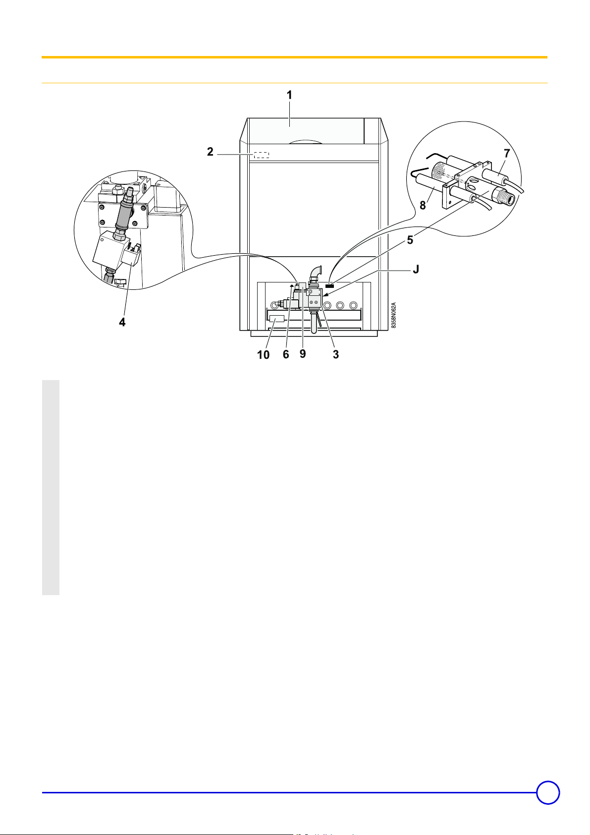
3.1 Boiler
1 Control panel
2 Safety box
The safety control box is fitted to the control panel and controls the
burner ignition, function and extinction sequences.
3 Multivalve gas unit:
It includes a safety valve and a 2-stage principal valve with filter and
minimum gas pressure switch.
4 Ignition burner valve
5 Ignition burner
6 Flame inspection window
7 Ionisation probe: It detects flame presence on the ignition burner by
flame ionisation.
8 Ignition electrode: This ensures ignition burner ignition using a high
voltage spark.
9 Minimum gas pressure switch
(Minimum pressure: 12.5 mbar)
10 Ignition box
06/02/06 - 300005247-001-B Remeha Gas 460 S
5
Page 6

3.2 Control panel
13-position switch Auto / Manual ! / TEST STB
- The switch may be left on either position manual ! or automatic AUTO.
- STB TEST: Temporary action to test the safety thermostat.
- Press the TEST STB switch and set pump shut-off switch (2) 9 to the “Summer” position %.
2 Switch Burner / Heating pump:
This button is used to control the burner and the heating pump.
Both buttons are in “Winter” . position: Heating and hot water production systems operate (if a hot water tank is included).
Both buttons are in “Summer” % position: The burner and the heating pump don't operate.
If the boiler is fitted with a control unit, both buttons must be left on the Winter . position.
3 Main ON/OFF switch
4 Location for hour run meter for the first and second stage (optional)
5 Boiler thermostat (30 to 90 °C):
A factory-set stop limits the maximum temperature to 75 °C. The stop may be moved if necessary.
6 Stage one or stage two indicators:
These only go on if the relevant thermostat or control unit require heating and if the safety contact is closed.
7 Boiler thermometer
8 Location for flue gas thermometer (optional)
9 Safety thermostat with manual reset (set to 110 °C).
10 10 A Circuit-breaker: with delayed action and manual reset.
11 Location for optional features or a RC4/RC5 control unit
13 Switch for selecting the number of burner stages
14 Burner alarm indicator + Reset button
6
Remeha Gas 460 S 06/02/06 - 300005247-001-B
Page 7

4 Technical characteristics
The boilers can operate on natural gases type H/L.
Boiler Gas 460 S / 8 10 12 14 16 18 20
Useful efficiency
Power input
Number of sections Part 8 101214161820
Mass flue gas flow rate
(1)
Flue gas temperature Tf
Boiler temperature 80°C
CO
2
Ionisation current µA 1.0
Required depressurisation at the
nozzle
Minimum outlet temperature °C 40
Maximum outlet temperature °C 90
Maximum operating pressure bar 6
Electrical connection V/Hz 230/50
Electrical output W 108 / 114 maximum
Gas connection 20 mbar inch 1" 1" 1" 1"1/4 1"1/4 1"1/4 1"1/2
Heating connection inch 2"
Internal diameter flue gas nozzle mm 250 300 300 350 350 350 400
Water resistance
(1)
Water capacity* l 61 76 91 106 122 137 154
Shipping weight kg 668 807 934 1096 1227 1364 1476
(1)
at 2nd stage
1st stage kW 83-98 107-126 131-154 155-182 179-210 202-238 226-266
2nd stage kW 119-140 153-180 187-220 221-260 255-300 289-340 323-380
1st stage kW
93.1-
108.9
2nd stage kW 131.1-153
kg per
sec
0.097 0.127 0.144 0.177 0.191 0.203 0.258
119.4-
139.7
168.2-
196.3
145.6-
170.4
205.2-
239.4
171.9-
201.1
242.2-
282.6
197.9-
231.5
278.8-
325.4
224-262.1
315.7-
368.4
250.1-
292.6
352.4-
411.3
°C 125 123 130 126 133 140 126
1st stage
2nd stage 5.4-6.4 5.3-6.3 5.8-6.8 5.5-6.5 6.0-7.0 6.5-7.5 5.5-6.5
%
3.9-4.9 3.8-4.8 4.3-5.3 4.0-5.0 4.5-5.5 5.0-6.0 4.0-5.0
daPa 0.7
∆ T = 10K
∆ T = 15K 36 59 88 123 164 211 263
mbar
80 133 198 277 369 484 592
∆ T = 20K 20 33 50 69 92 118 148
1 mbar = 10 mmCE = 10 daPa = 100 Pa
06/02/06 - 300005247-001-B Remeha Gas 460 S
7
Page 8
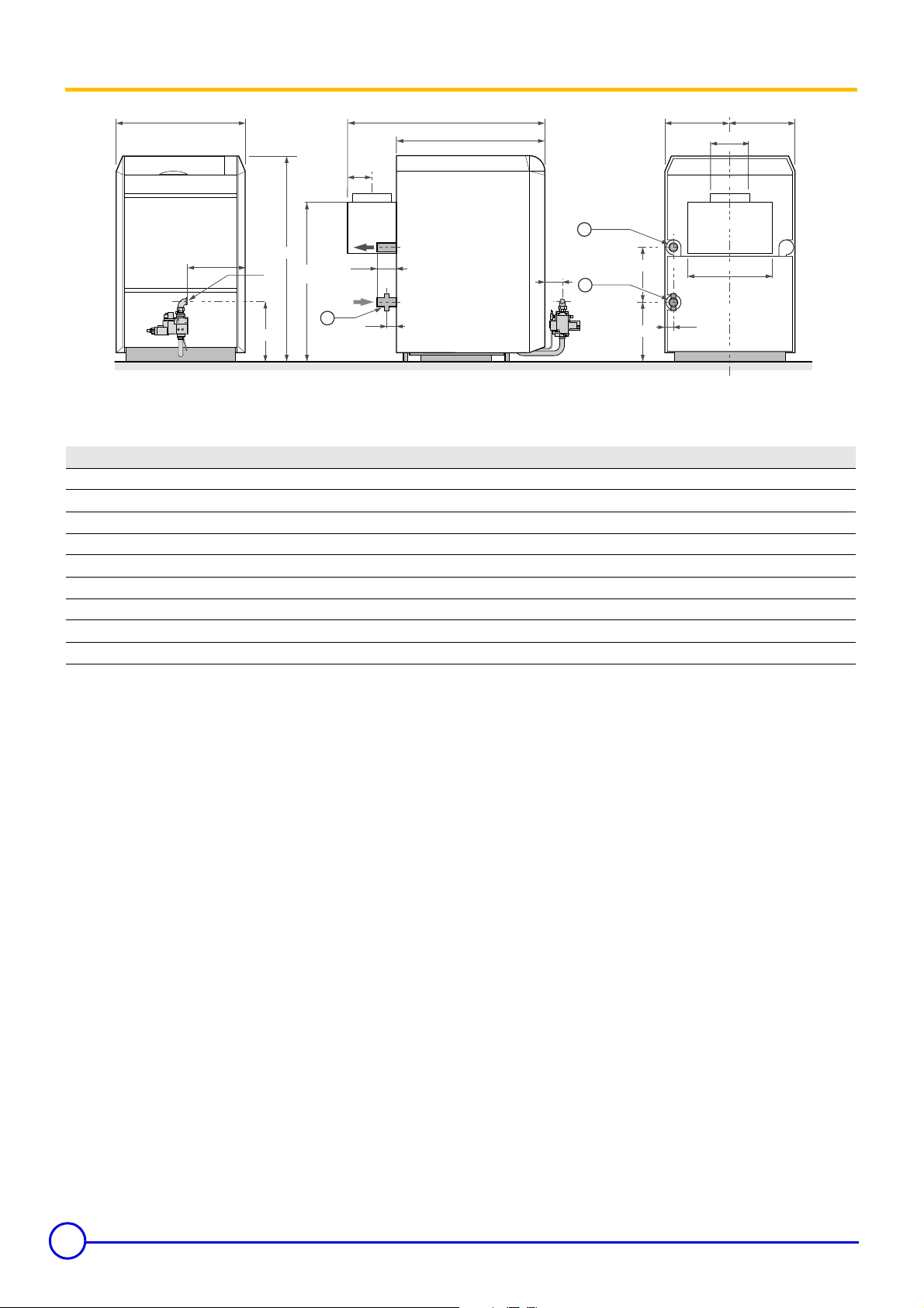
5 Main dimensions
Heating outlet R 2
Heating return R 2
8358N061A
B
E
ø F
1406
J
H
130
3
60
G
A
1006
1
375
410
130
2
Draining Rp 3/4
= =
ø C
D
64
Boiler Gas 460 S /8 /10 /12 /14 /16 /18 /20
A (mm) 1362 1362 1362 1412 1412 1412 1462
B (mm) 970 1146 1322 1498 1674 1850 2026
Ø C (mm) 250 300 300 350 350 350 400
D (mm) 632 808 984 1160 1336 1512 1688
E (mm) 165 165 165 190 190 190 220
Ø F (mm) (20/25 mbar) Rp1 Rp1 Rp1 Rp1 1/4 Rp 1 1/4 Rp 1 1/4 Rp 1 1/2
Ø F (mm) (300 mbar) Rp 3/4
G 447 535 623 704 792 880 963
H 445 445 445 454 454 454 507
J 1094 1094 1094 1194 1194 1194 1194
8
Remeha Gas 460 S 06/02/06 - 300005247-001-B
Page 9

Operation
1 Furnace operation equipped with safety box RV 00 54 / 000 00
Operating principle
The boiler can operate at either 2nd stage or 1st stage depending on
the thermal needs of the installation.
The ignition and burner surveillance sequences are ensured by the
safety box.
Behaviour in normal conditions
The box closes the TCH contact when there is a requirement for
heat1. The safety control box runs an auto-check of around 1
second(s) by lighting the alarm warning light VA.
In the case of an offset alarm, it is necessary to use a timed
relay in order to prevent an unjustified alarm signal.
After a waiting time tw, the ignition transformer TA produces a series
of sparks at the ignition electrode. After a pre-ignition period tvz, the
ignition burner valve VG and the safety valve VS open. Formation of
flame in ignition burner. The ionisation sensor SF shows a flame
signal with a minimum ionisation current of 1 µA and ignition is shut
down. After a period of stabilisation tstab, the principal burner ignites
at 1st stage BR1 (or at 2nd stage if the 2nd stage thermostat TCH2
is needed).
Behaviour in abnormal conditions
- If a flame is not detected before the safety time ts, the box makes
2 more ignition attempts. If, at the end of the last attempt, there is
still no flame signal, the box goes into safety and the safety
indicator comes on. To restart the heater, press the reset button on
the safety box.
- If there is a loss of flame in normal operation, the box automatically
repeats the start up sequence.
Resetting
The box is reset after going into safety by pressing the reset button.
If the reset button does not work, wait at least 15 seconds before
trying a second time. After activating the reset button, the warning
light goes out and the safety control box restarts after a waiting time
of around 1 minute.
Note 1: The box may be on safety on its first start up: press the reset
button to release it.
Note 2: If the reset button is pressed in normal operation, the gas
valves close and the box starts a new ignition sequence.
06/02/06 - 300005247-001-B Remeha Gas 460 S
9
Page 10
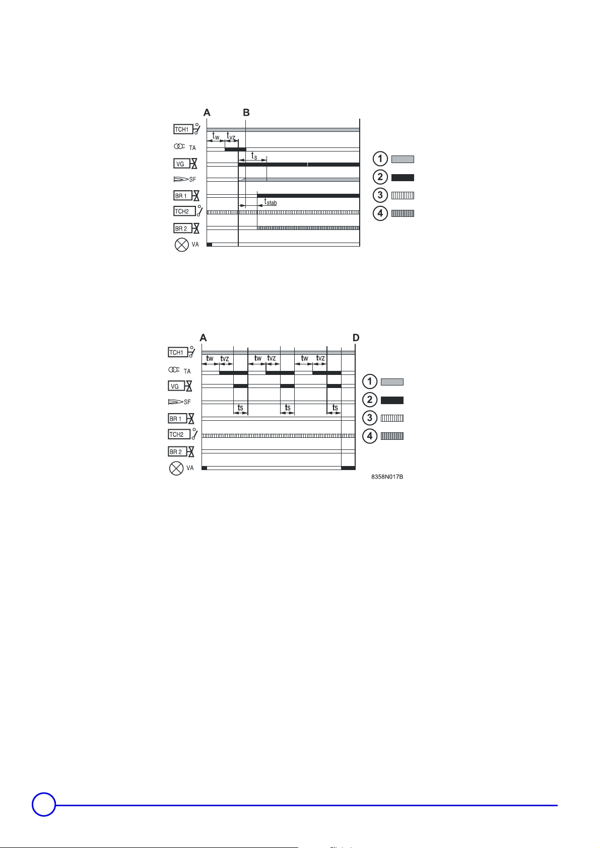
Normal operating cycle
Operating cycle on safety (start up without flame signal)
8358N016A
Required input signals
Box output signals
Thermostatic request at 2nd stage
Operation 2nd stage
A Start of operation
B Formation of flame in ignition burner
BR1 1st stage
BR2 2nd stage
SF Burner flame signal
TA Ignition transformer
TCH1 Boiler thermostat 1 Speed
TCH2 Boiler thermostat 2 Speed
VA Safety lockout warning light
VG Ignition burner valve + Safety valve VS
ts Safety time: maximum 10 seconds
tstab Flame stabilisation time: 5 seconds
tvz Pre-ignition time: 10 seconds
tw Waiting time: 0 seconds
10
Remeha Gas 460 S 06/02/06 - 300005247-001-B
Page 11
Adapting to another gas
These actions must be carried out by a qualified
technician.
1 Changing gas
The boilers are factory-set to operate on natural gas H (G20 - 20
mbar). To convert it to natural gas L, use the gas L conversion kit
(optional). Carry out the operations described below.
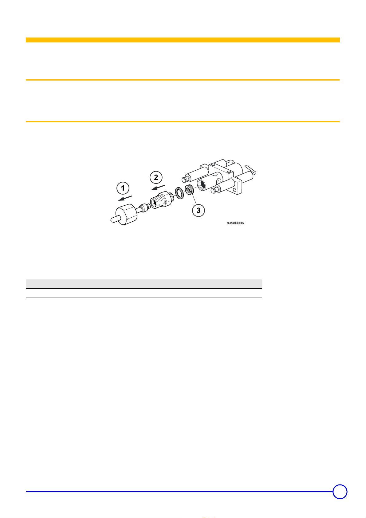
2 Changing the ignition burner injector
Operations to be carried out to convert from natural gas H to natural
gas L and vice versa:
Belgium: The operations required to switch from one gas
to another must be carried out by a SERV'elite technician.
Remove the gas supply pipe from the ignition burner (13 mm
spanner).
Remove the nozzle + seal.
Natural gas H Natural gas L
Nozzle marking 80 100
Nozzle diameter 0.80 mm 1.00 mm
Unscrew the nozzle using a screwdriver and screw in the new
injector.
- Reassemble the parts
- Carry out a leak tightness check
06/02/06 - 300005247-001-B Remeha Gas 460 S
11
Page 12
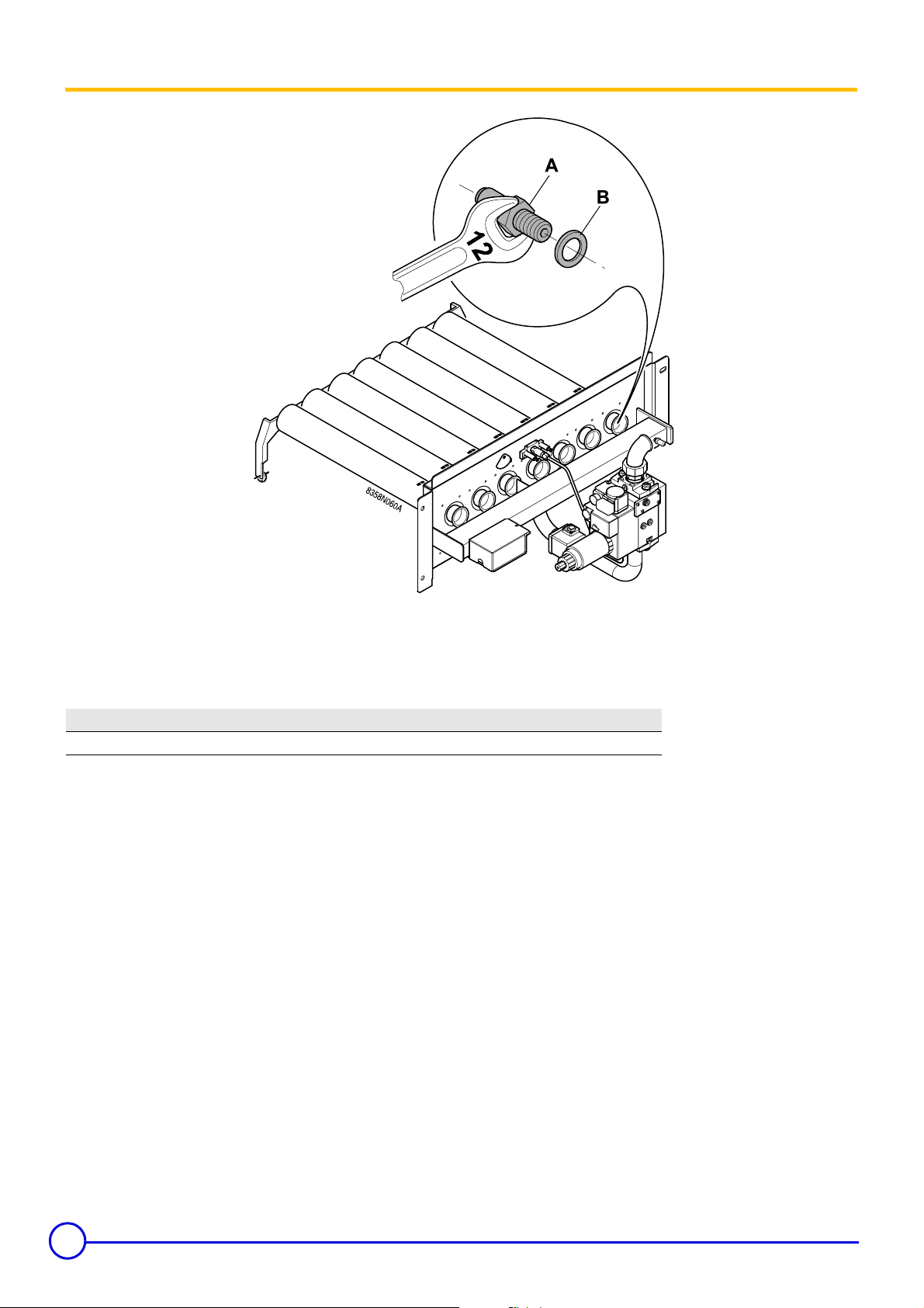
3 Changing the burner injectors
- Close the gas valve.
- Lift out the injector with a number 12 spanner assemble the new
injectors with their new joint.
Natural gas H Natural gas L
Nozzle marking 390A 450A
Nozzle diameter 3.9 mm 4.5 mm
First tighten the injectors by hand and carefully lock them using
a spanner.
- Carry out a leak tightness check.
12
Remeha Gas 460 S 06/02/06 - 300005247-001-B
Page 13
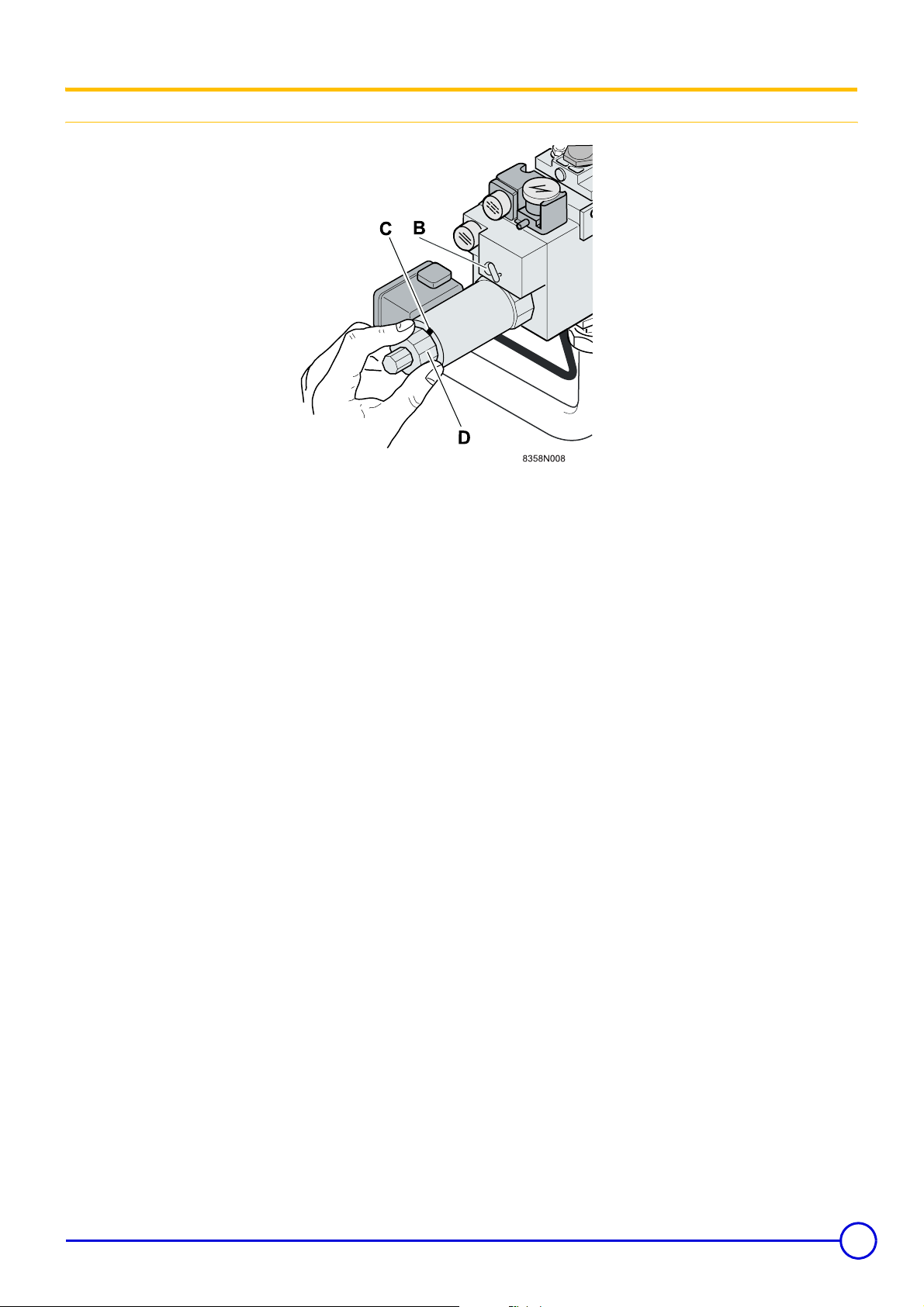
4 Setting the injector pressure
Setting the pressure 2nd stage
The pressure must be set by a qualified professional.
The boiler must be commissioned after having checked the points
covered in this chapter: Final checks before commissioning.
- Connect a manometer to the pressure outlet.
- Run the boiler at 2nd stage, activating the thermostat(s).
- Set the pressure at the injectors as follows:
- Free the cylindrical split head screw C by around one turn. Fully
unscrew the setting button
C
.
- Set the pressure at the injectors by turning the screw on the
regulator
the left, you decrease the principal flow.
If you find you cannot tighten screw B any further before
reaching the desired pressure, unscrew B again by a quarter
turn and continue the setting by turning D after freeing the
inhibitor screw C.
B
. By turning to the right, you increase and, by turning to
D
(anti-clockwise). Tighten the screw
- On propane, the regulator B is fully tightened. It is not used.
06/02/06 - 300005247-001-B Remeha Gas 460 S
13
Page 14
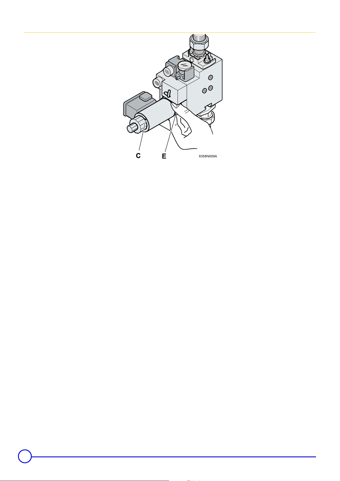
Setting the pressure 1st stage
- Run the boiler at 1st stage by activating the burner on selector
switch on the boiler control panel.
- Set the flow in such a way as to obtain pressure at the injectors (0.5
x Pressure 2nd stage):
- Set the 1st stage flow with the ring E.
- By turning to the right, you increase and, by turning to the left, you
decrease the principal flow.
- Tighten the inhibitor screw
C
.
14
Remeha Gas 460 S 06/02/06 - 300005247-001-B
Page 15
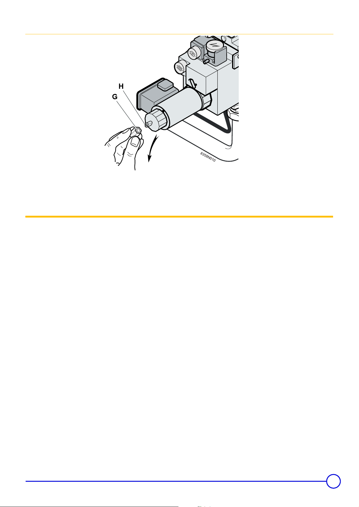
Setting the start-up progressivity (or initial flow)
In the factory, the progressivity is set to minimum (low start-up
pressure).
Depending on the installation conditions, adjust the progressivity
setting in order to guarantee optimum boiler start-up.
5 Checking the minimum gas pressure switch setting
The minimum gas pressure switch on the safety valve is set in the
factory to a value of 12.5 mbar, which corresponds to the setting for
natural gas.
To operate on propane, set the start-up pressure to 20 mbar.
- Unscrew the protection cap G. Use like a spanner to turn the
setting rod H until you obtain the desired initial flow.
- Put the cap back in place.
06/02/06 - 300005247-001-B Remeha Gas 460 S
15
Page 16
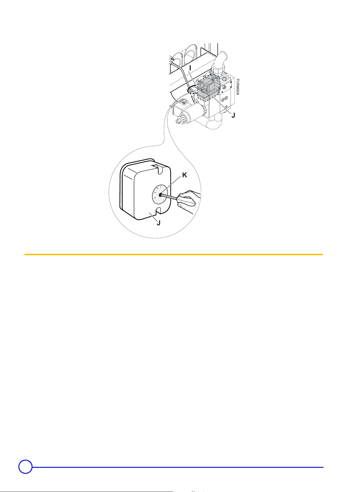
If there is a drop in the gas supply pressure, the minimum pressure
switch shuts down the boiler.
6 Attaching the label
Affix the label which indicates for which type of gas the boiler is fitted
and set.
16
Remeha Gas 460 S 06/02/06 - 300005247-001-B
Page 17

Commissionning
1 Pressure settings and calibrated injector markings
1.1 Table of pressure settings and injector markings + Flow table (15°C - 1013 mbar)
Boiler type Gas 460 S / 8 10 12 14 16 18 20
Useful efficiency
1st stage kW 83-98 107-126 131-154 155-182 179-210 202-238 226-266
2nd stage kW 140 180 220 260 300 340 380
Power input
1st stage kW 93.1-108.9 119.4-139.7 145.6-170.4 171.9-201.1 197.9-231.5 224-262.1 250.1-292.6
2nd stage kW 131.1-153 168.2-196.3 205.-239.4 242.2-282.6 278.8-325.4 315.7-368.4 352.4-411.3
Nozzle
Diameter, principal burner injector
Gas H
Diameter, principal burner injector
Gas L
Diameter, ignition
burner injector
Gas flow rate
Gas H
Gas L
Downstream gas pressure
Gas H
Gas L
Gas H mm 0.8
Gas L mm 1.0
1st stage
2nd stage 13.88-16.19 17.80-20.77 21.71-25.33 25.63-29.91 29.51-34.43 33.40-38.98 37.29-43.52
1st stage
2nd stage 16.14-18.83 20.70-24.16 25.25-29.46 29.81-37.78 34.32-40.05 38.85-45.34 43.38-50.62
1st stage
2nd stage 90-120
1st stage
2nd stage 74-100
mm 3.9
mm 4.5
3
m
/h
3
m
/h
mmCE
mmCE
9.35-11.52 12.63-14.78 15.41-18.03 18.19-21.28 20.94-24.50 23.71-27.74 26.47-30.97
11.46-13.40 14.70-17.19 17.92-20.97 21.16-24.75 24.36-28.50 27.57-32.26 30.78-36.02
Pressure 1st stage = 0.5 x 2nd stage pressure set
Pressure 1st stage = 0.5 x 2nd stage pressure set
06/02/06 - 300005247-001-B Remeha Gas 460 S
17
Page 18
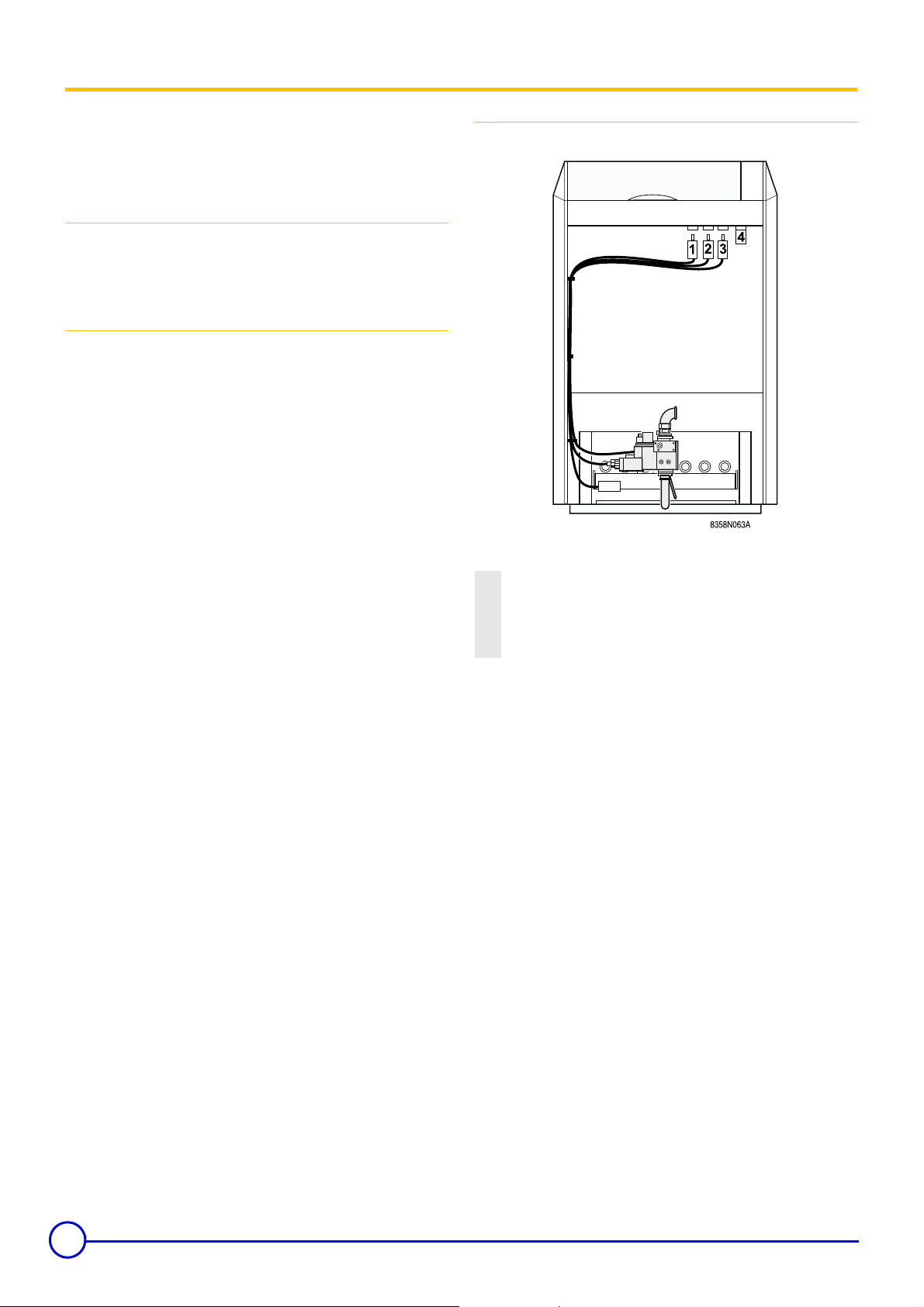
2 Final checks before commissioning
The first start-up is to be performed by your installation
engineer.
Make the gas line setting before commissioning.
Check the following points before starting the heater:
Hydraulic circuit:
`Check that the installation and boiler are adequately filled with
water and correctly irrigated and bled.
`Check that the hydraulic connections are leak tight.
Gas circuit:
`Check the adjustment of the gas line:
- Connect a manometer to the pressure socket located on the
manifold.
- Check that the nozzle pressure and the start-up pressure match
the pressures given in the relevant chapter: Pressure settings and
calibrated injector markings.
If necessary, adjust the pressure as shown in the relevant
chapters: Setting the injector pressure.
Electrical connectors:
Check that the connectors under the control panel are correctly fitted:
1 Ignition circuit
2 Gas pressostat
3 Gas valve circuit
4 Leak proofing system (Options RE 30)
18
Remeha Gas 460 S 06/02/06 - 300005247-001-B
Page 19

1 Checking and cleaning the main components
1.1 Cleaning heater body
Maintenance
8N
835 022
The extent of clogging on the heating body must be checked once a
year.
If it is necessary to sweep the boiler, remove the burner drawer to
prevent deposits and soot blocking the orifices in the gas trains.
With the burner out:
- Remove the upper casing of the boiler
- Take out the insulation
- Remove the sweeping hatch from the draught diverter
- If necessary, clean the boiler body using the special brush
provided
- Clean the combustion chamber using a vacuum cleaner
06/02/06 - 300005247-001-B Remeha Gas 460 S
19
Page 20
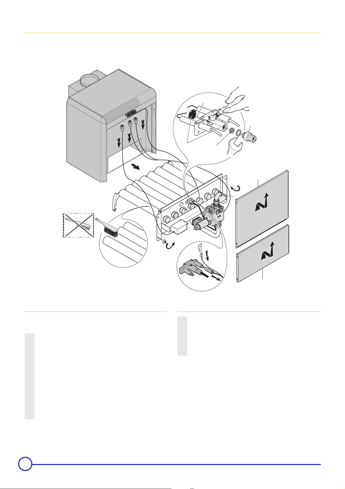
1.2 Cleaning main burner and ignition burner
The main burner and the ignition burner injector with its filter must be
regularly cleaned to ensure good performance. We recommend
doing this at least once a year.
3
4
5
9
These actions must be carried out by a qualified
technician.
13
10
12
11
13
2
7
Main burner
- Switch off the boiler electrical power supply
- Cut the gas supply
1 Remove the lower cladding panel
2 Remove the intermediate cladding panel
3 Disconnect the valve connector
Disconnect the gas pressure switch connector (and the leak proofing
4
cyclical control system, if there is one) under the control panel
5 Disconnect the ignition circuit
Disconnect the ionisation cable and the ground conductor on the
6
ionisation sensor side
7 Unscrew the union joint on the gas inlet pipe
8 Unscrew the 4 holding nuts on the burner drawer
9 Take out the burner drawer
8
6
8358N064A
1
Ignition burner
Remove the gas supply pipe from the ignition burner (13 mm
10
spanner)
11 Clean the injector
12 Clean the ignition burner
13 Clean the flame stabilisation pipe located inside the ignition burner
Do not use a metal brush.
- Clean the burner trains (slits) using a soft brush, a short-handled
brush or a vacuum cleaner.
20
Remeha Gas 460 S 06/02/06 - 300005247-001-B
Page 21

1.3 Painted surfaces
The painted surfaces can be cleaned with tepid or cold soapy water.
Wipe the painted surfaces with a soft cloth or a damp sponge.
06/02/06 - 300005247-001-B Remeha Gas 460 S
21
Page 22
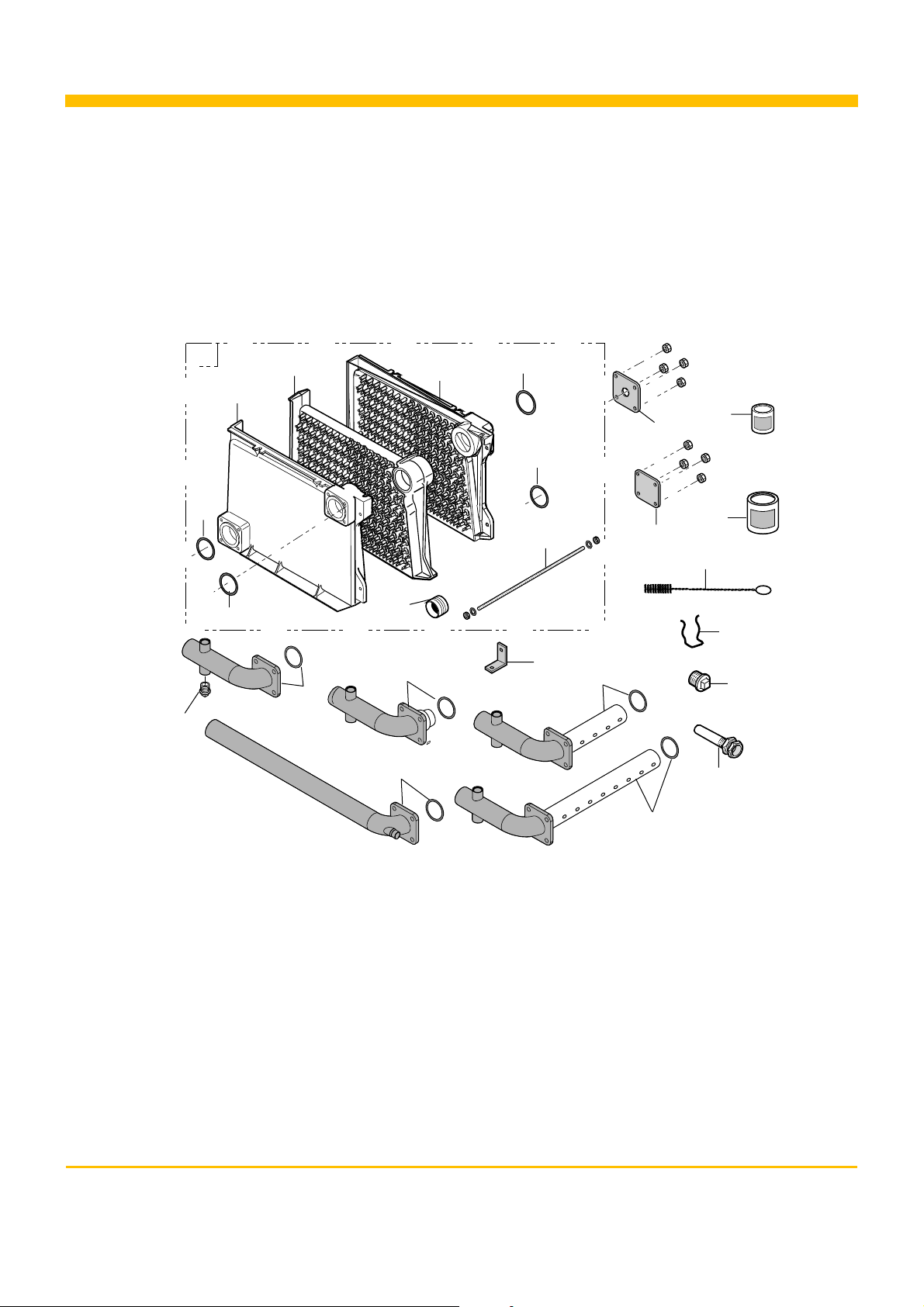
Spare parts Gas 460 S
The code number on the list next to the required piece must be stated when ordering replacement parts.
Boiler body
01/10/05 - 300005247-002-A
17
15
1
2
15
4
11
3
5
11.1
12
15
15
8
18
11.2
6
14
7
13
19
10
16
9
11.3
Page 23
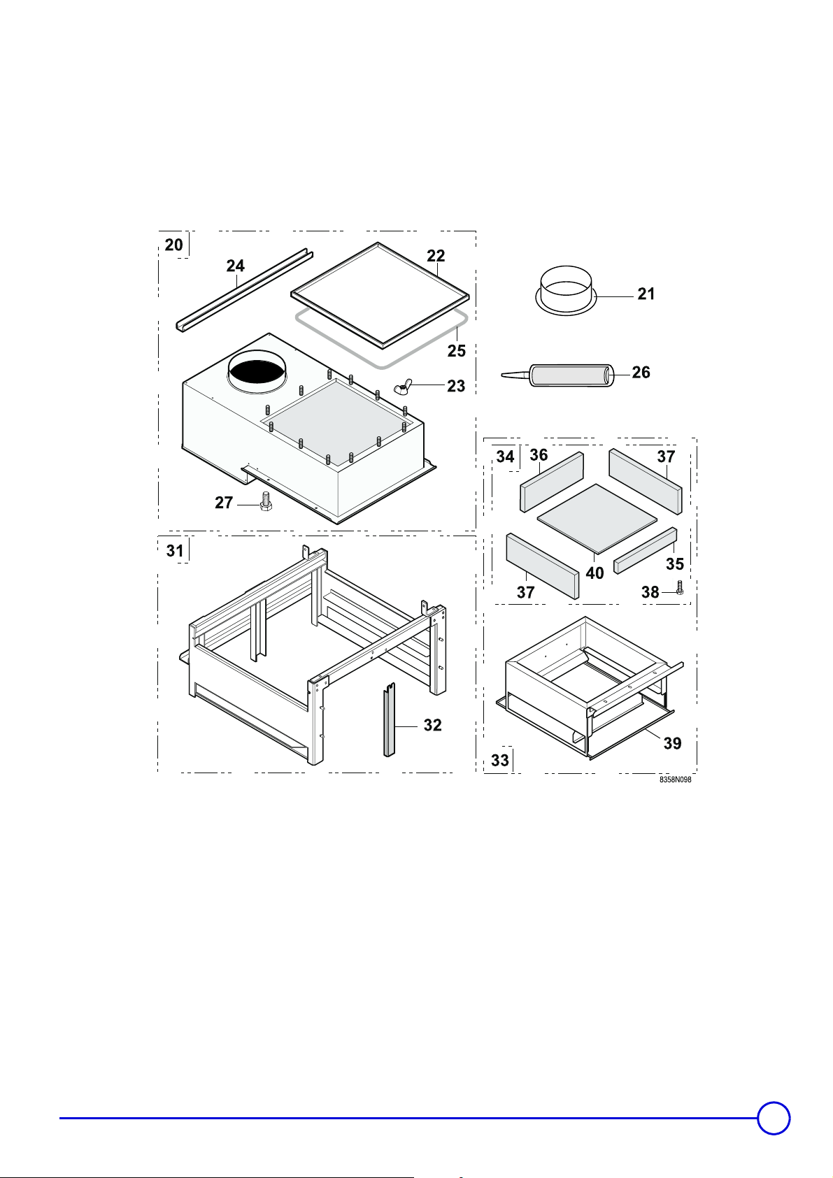
Base frame + Draught diverter
06/02/06 - 300005247-001-B Remeha Gas 460 S
23
Page 24
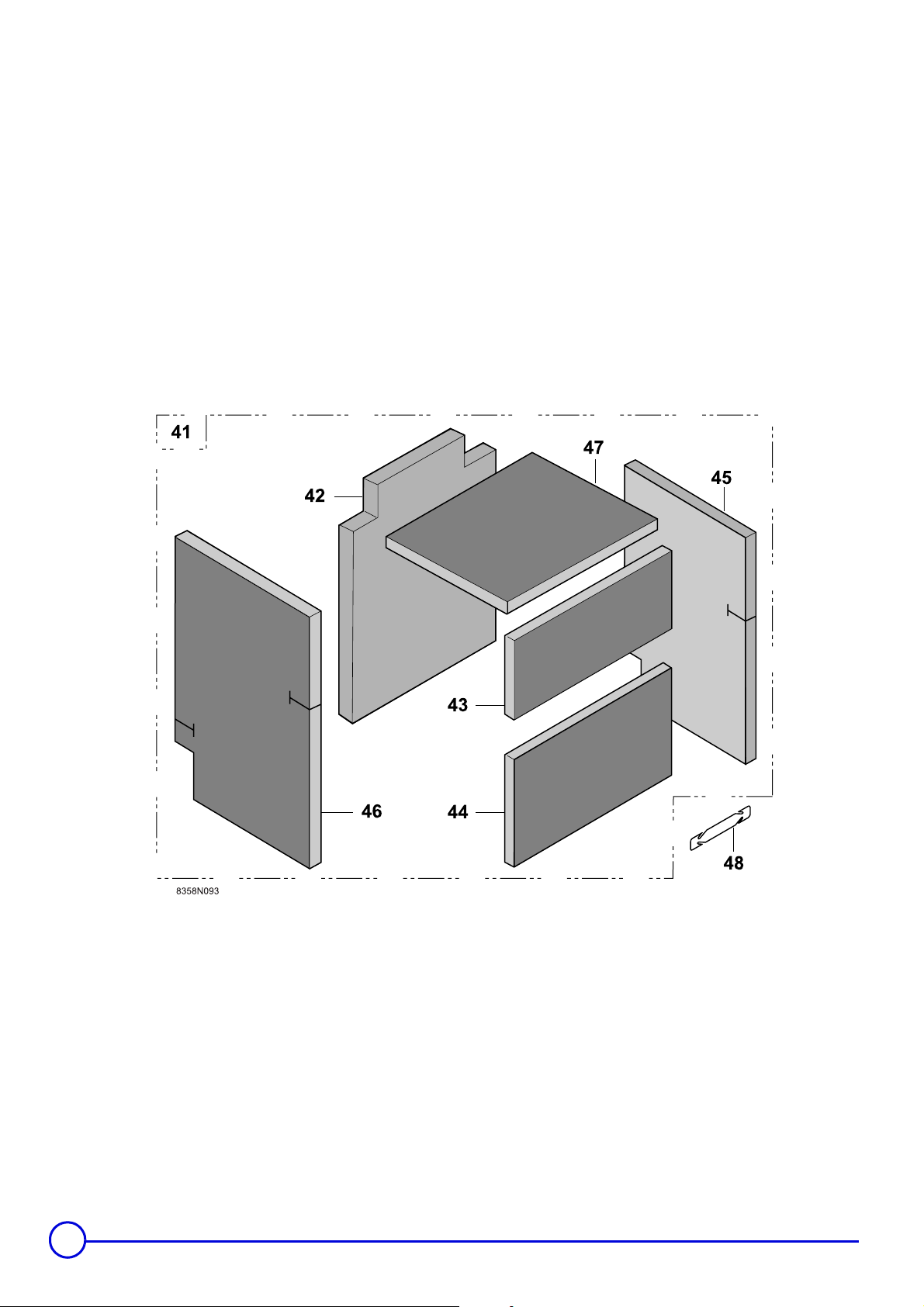
Insulation
24
Remeha Gas 460 S 06/02/06 - 300005247-001-B
Page 25
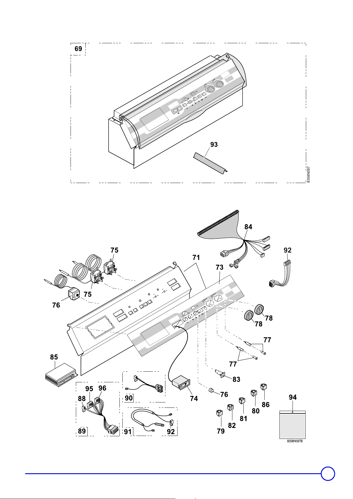
Control panel K
Control panel K + Components
06/02/06 - 300005247-001-B Remeha Gas 460 S
25
Page 26
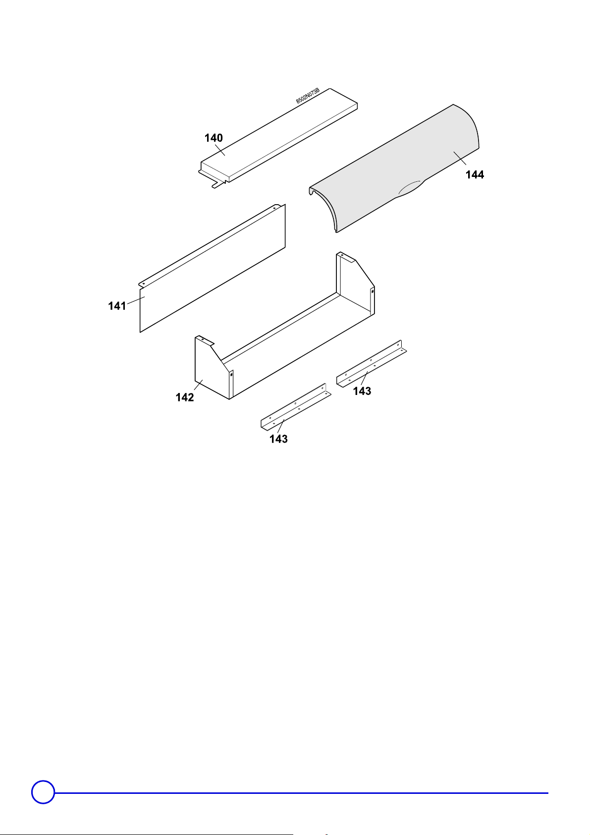
Metal casing for control panel K
26
Remeha Gas 460 S 06/02/06 - 300005247-001-B
Page 27
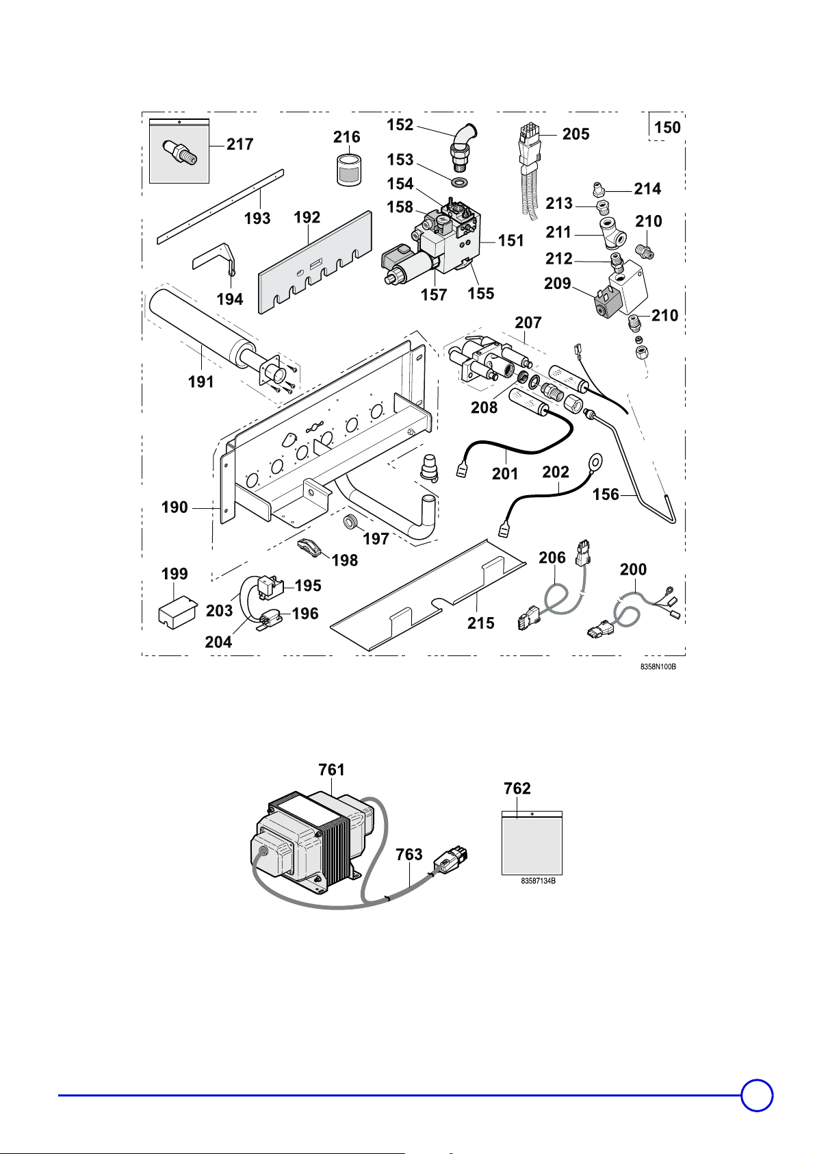
Gas line 20 mbar
Circuit separation transformer
06/02/06 - 300005247-001-B Remeha Gas 460 S
27
Page 28
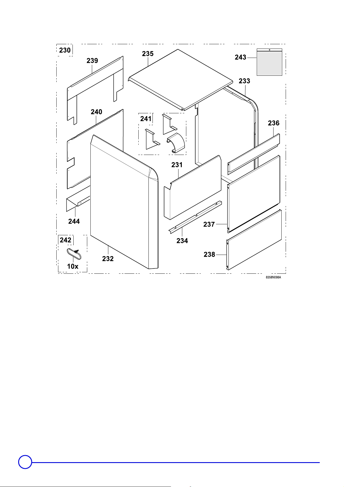
Cladding
28
Remeha Gas 460 S 06/02/06 - 300005247-001-B
Page 29
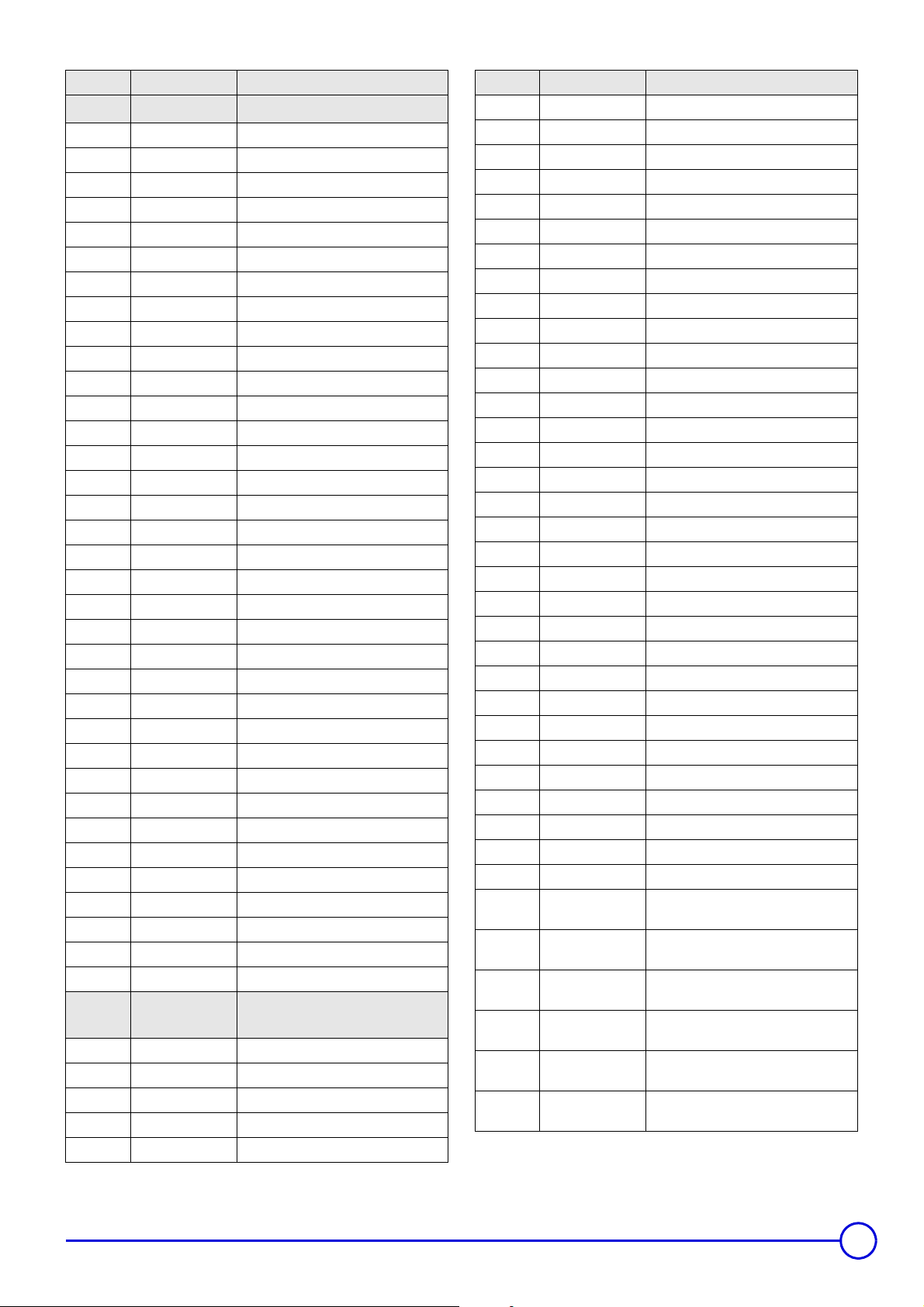
Markers Code no. Description
BOILER BODY
1 8358-5500 Boiler body - 8 sections
1 8358-5502 Boiler body - 10 sections
1 8358-5504 Boiler body - 12 sections
1 8358-5505 Boiler body - 14 sections
1 8358-5506 Boiler body - 16 sections
1 8358-5507 Boiler body - 18 sections
1 8358-5508 Boiler body - 20 sections
2 8358-5509 Lateral section left
3 8358-5510 Lateral section right
4 8358-5511 Intermediate section
5 8116-0571 Nipple
6 8800-8966 Box of mastic (1 kg)
7 9430-5027 Putty for nipple 300g
8 8345-7020 Assembly rod LG670
8 8345-7022 Assembly rod Ø 10 x 870
8 8345-7024 Assembly rod Ø 10 x 1010
8 8345-7025 Assembly rod Ø 10 x 1195
8 8345-7026 Assembly rod Ø 10 x 1370
8 8345-7027 Assembly rod Ø 10 x 1550
8 8358-5512 Assembly rod M10 - 1730
9 9536-5611 Sensor tube 1/2"
10 9758-1286 Contact spring for thimble tube
11 8358-5554 Return pipe + Gasket - 8 sections
11.1 8358-5582 Return pipe + Gasket - 10 sections
11.2 8358-5560 Return pipe + Gasket - 12-16 sections
11.3 8358-5555 Return pipe + Gasket - 18-20 sections
12 8358-5553 Outlet pipe + Gasket
13 9758-1697 Plain square flange
14 9758-1119 Square flange with tapped hole 1/2"
15 9758-1630 Flange gasket
16 9495-0110 Plug 1/2"
17 9495-0140 Plug 3/4"
18 8345-0501 Locating lug
19 9750-5037 Brush
BASE FRAME + DRAUGHT
DIVERTER
20 8358-8501 Draught diverter complete - 8 sections
20 8358-8503 Draught diverter complete - 10 sections
20 8358-8505 Draught diverter complete - 12 sections
20 8358-8506 Draught diverter complete - 14 sections
20 8358-8507 Draught diverter complete - 16 sections
Markers Code no. Description
20 8358-8508 Draught diverter complete - 18 sections
20 8358-8509 Draught diverter complete - 20 sections
21 8116-8078 Nozzle Ø 250 - 8 sections
21 8345-8217 Nozzle Ø 300 - 10-12 sections
21 8345-8218 Nozzle Ø 350 - 14-18 sections
21 8123-8193 Nozzle Ø 400 - 20 sections
22 8358-5513 Sweeping plate - 8 sections
22 8358-5515 Sweeping plate - 10 sections
22 8358-5517 Sweeping plate - 12 sections
22 8358-5518 Sweeping plate - 14 sections
22 8358-5519 Sweeping plate - 16 sections
22 8358-5520 Sweeping plate - 18 sections
22 8358-5521 Sweeping plate - 20 sections
23 9587-0055 M6 wing nut
24 8358-8050 Rear upper cross-bar - 8 sections
24 8358-8052 Rear upper cross-bar - 10 sections
24 8358-8054 Rear upper cross-bar - 12 sections
24 8358-8055 Rear upper cross-bar - 14 sections
24 8358-8056 Rear upper cross-bar - 16 sections
24 8358-8057 Rear upper cross-bar - 18 sections
24 8358-8058 Rear upper cross-bar - 20 sections
25 8358-5561 Sweeping plate seal
26 9428-5095 Silicone filler tube
27 8358-5522 Fixing screw
31 8358-8739 Complete frame 8 sections
31 8358-8741 Complete frame 10 sections
31 8358-8743 Complete frame 12 sections
31 8358-8744 Complete frame 14 sections
31 8358-8745 Complete frame 16 sections
31 8358-8746 Complete frame 18 sections
31 8358-8747 Complete frame 20 sections
32 9758-1180 Central foot, rear
33 8358-8706
33 8358-8708
33 8358-8710
33 8358-8711
33 8358-8712
33 8358-8713
Complete combustion chamber - 8
sections
Complete combustion chamber - 10
sections
Complete combustion chamber - 12
sections
Complete combustion chamber - 14
sections
Complete combustion chamber - 16
sections
Complete combustion chamber - 18
sections
06/02/06 - 300005247-001-B Remeha Gas 460 S
29
Page 30
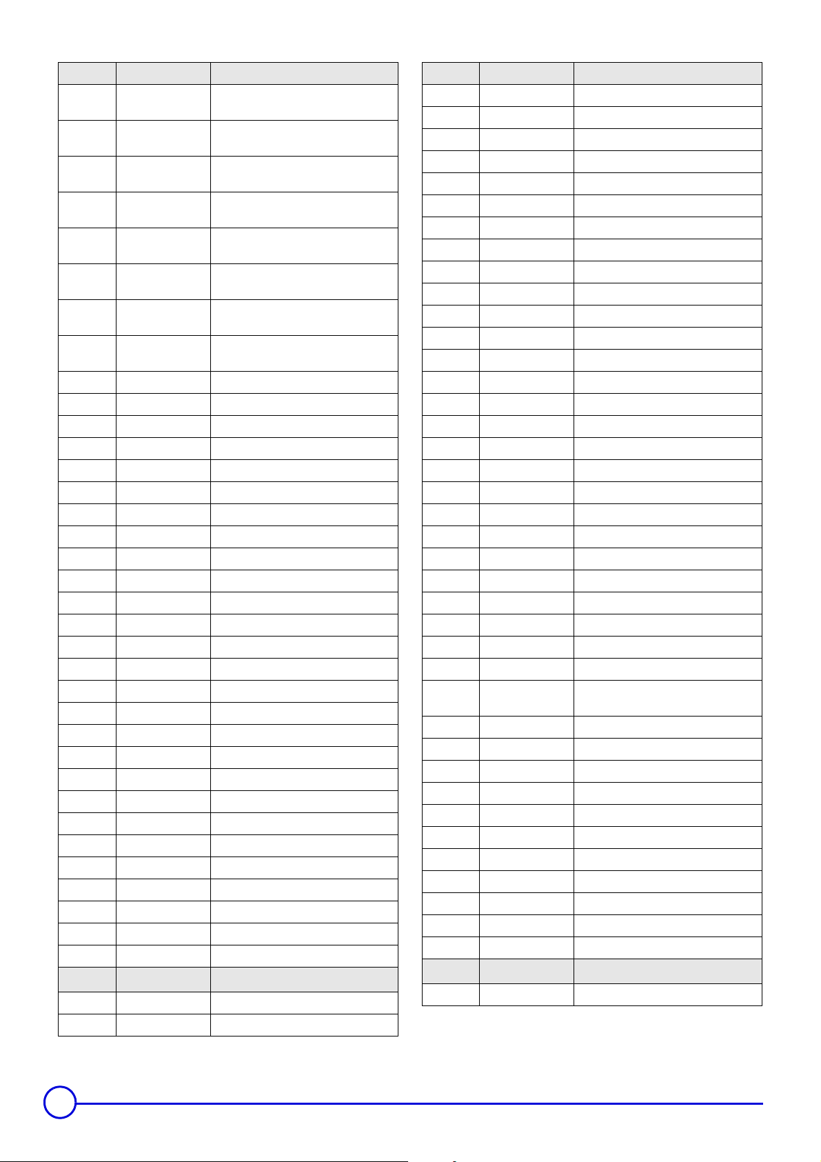
Markers Code no. Description
33 8358-8714
34 8358-8791
34 8358-8793
34 8358-8795
34 8358-8796
34 8358-8797
34 8358-8798
34 8358-8799
35 9422-9236 Front insulation - 8 sections
35 9422-9238 Front insulation - 10 sections
35 9422-9240 Front insulation - 12 sections
35 9422-9241 Front insulation - 14 sections
35 9422-9242 Front insulation - 16-18-20 sections
36 9422-9277 Rear insulation - 8 sections
36 9422-9279 Rear insulation - 10 sections
36 9422-9281 Rear insulation - 12 sections
36 9422-9282 Rear insulation - 14 sections
36 9422-9283 Rear insulation - 16-18-20 sections
37 9422-9284 Side insulating material
38 8358-5557 Fixing screw
39 8358-1560 Painted tank - 8 sections
39 8358-1562 Painted tank - 10 sections
39 8358-1564 Painted tank - 12 sections
39 8358-1565 Painted tank - 14 sections
39 8358-1566 Assembled tank - 16 sections
39 8358-1567 Assembled tank - 18 sections
39 8358-1568 Assembled tank - 20 sections
40 9422-9286 Tank insulation - 8 sections
40 9422-9288 Tank insulation - 10 sections
40 9422-9290 Tank insulation - 12 sections
40 9422-9291 Tank insulation - 14 sections
40 9422-9292 Tank insulation - 16 sections
40 9422-9293 Tank insulation - 18 sections
40 9422-9294 Tank insulation - 20 sections
Complete combustion chamber - 20
sections
Complete combustion chamber insulation
- 8 sections
Complete combustion chamber insulation
- 10 sections
Complete combustion chamber insulation
- 12 sections
Complete combustion chamber insulation
- 14 sections
Complete combustion chamber insulation
- 16 sections
Complete combustion chamber insulation
- 18 sections
Complete combustion chamber insulation
- 20 sections
Markers Code no. Description
41 8358-5527 Insulating material for body - 12 sections
41 8358-5528 Insulating material for body - 14 sections
41 8358-5529 Insulating material for body - 16 sections
41 8358-5530 Insulating material for body - 18 sections
41 8358-5531 Insulating material for body - 20 sections
42 8358-4004 Rear insulation - 8 sections
42 8358-4006 Rear insulation - 10 sections
42 8358-4008 Rear insulation - 12 sections
42 8358-4009 Rear insulation - 14 sections
42 8358-4010 Rear insulation - 16 sections
42 8358-4011 Rear insulation - 18 sections
42 8358-4012 Rear insulation - 20 sections
43 8358-4014 Upper front insulation - 8 sections
43 8358-4016 Upper front insulation - 10 sections
43 8358-4018 Upper front insulation - 12 sections
43 8358-4019 Upper front insulation - 14 sections
43 8358-4020 Upper front insulation - 16 sections
43 8358-4021 Upper front insulation - 18 sections
43 8358-4022 Upper front insulation - 20 sections
44 8358-4024 Lower front insulation - 8 sections
44 8358-4026 Lower front insulation - 10 sections
44 8358-4028 Lower front insulation - 12 sections
44 8358-4029 Lower front insulation - 14 sections
44 8358-4030 Lower front insulation - 16 sections
44 8358-4031 Lower front insulation - 18 sections
44 8358-4032 Lower front insulation - 20 sections
45 8358-4033 Side insulation, right - 8-10-12 sections
45 8358-4034
46 8358-4035 Side insulation, left - 8-10-12 sections
46 8358-4036 Side insulation, left - 14-16-18-20 sections
47 8358-4038 Upper insulation - 8 sections
47 8358-4040 Upper insulation - 10 sections
47 8358-4042 Upper insulation - 12 sections
47 8358-4043 Upper insulation - 14 sections
47 8358-4044 Upper insulation - 16 sections
47 8358-4045 Upper insulation - 18 sections
47 8358-4046 Upper insulation - 20 sections
48 8406-8082 Fastening
Side insulation, right - 14-16-18-20
sections
BOILER BODY INSULATION
41 8358-5523 Insulating material for body - 8 sections
41 8358-5525 Insulating material for body - 10 sections
30
CONTROL PANEL K
69 200003771 Control panel
Remeha Gas 460 S 06/02/06 - 300005247-001-B
Page 31
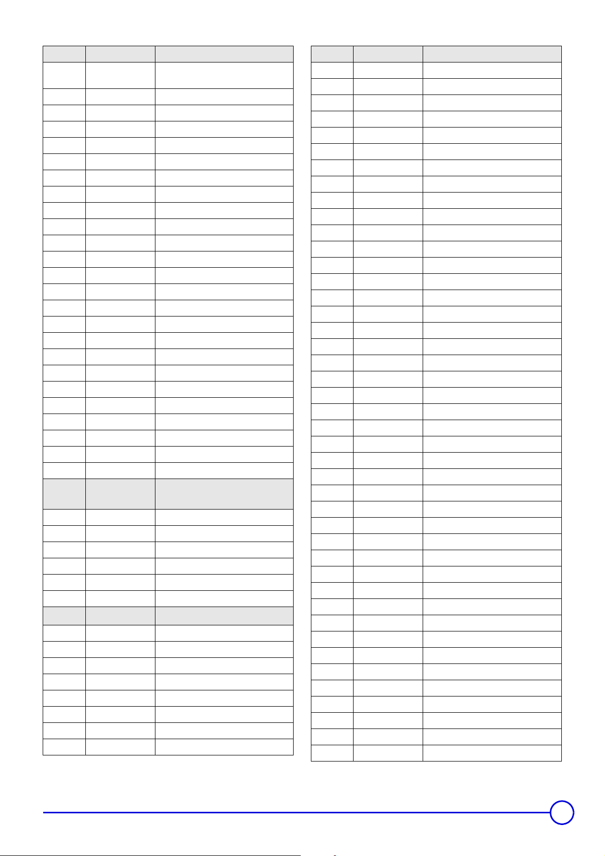
Markers Code no. Description
71 200003824
73 9421-0705 Control panel front cover K
74 9536-5157 Flat thermometer
75 8500-0002 Thermostat adjustable from 30 to 90°C
76 8500-0032 Safety thermostat 110°C
77 9521-6281 Round green indicator
78 8555-5501 Setting button + Pin
79 9532-5027 Green S/S bipolar switch
80 9532-5102 Reset switch
81 8500-0034 Momentary bipolar switch
82 8500-0035 Bipolar switch
83 9534-0288 4A TS710/4A Circuit-breaker
84 8358-4900 Control panel harness K
85 200001996 Safety box RV 0054100000
86 9532-5103 Bipolar switch
88 8358-4907 1-5 connector, assembled DGAI. 73
89 8358-4904 Power supply harness
90 8358-4912 3 pin IT-AMP circuit
91 8358-4905 Ionisation sensor circuit
92 200003258 Harness for third party control unit
93 9758-1286 Spring for pocket
94 8502-5519 Fasteners
95 8358-4908 1-6 connector, assembled DGAI. 73
96 8358-4909 7-8 connector, assembled DGAI. 73
Front panel support + CMF facade
cladding
METAL CASING FOR
CONTROL PANEL K
140 8358-8720 Protection cap
141 8358-5559 Card supports
142 8358-5558 Control panel bracket
143 8502-5560 Piano hinges (2 items)
144 8387-5556 Flap
GAS LINE - 20 MBAR
150 8388-8696 Gas line - 8 sections
150 8358-8698 Gas line - 10 sections
150 8358-8700 Gas line - 12 sections
150 8358-8701 Gas line - 14 sections
150 8358-8702 Gas line - 16 sections
150 8358-8703 Gas line - 18 sections
150 8358-8704 Gas line - 20 sections
151 9536-1561 Valve MB-ZRDLE 410B01
Markers Code no. Description
151 9536-1562 Valve MB-ZRDLE 412B01
151 9536-1563 Valve MB-ZRDLE 415B01
152 9496-0535 Union elbow 1"
152 9496-0536 Union elbow 1"1/4
152 9496-0537 Union elbow 1"1/2
153 9501-3064 Green seal 44x32x2
153 9501-3065 Green seal 56x42x2
153 9501-3066 Green seal 62x46x2
154 9754-9204 Clamp + Plug 1"
154 9754-9205 Clamp + Plug 1"1/4
154 9754-9213 Clamp + Plug 1"1/2
155 9754-9212 Gas flange with pressure socket 1"
155 9536-1003 Gas flange with pressure socket 1"1/4
155 9754-9214 Gas flange with pressure socket 1"1/2
156 8358-5583 Pilot burner pipe
157 9754-9216 Knob
158 9764-6000 Gas pressostat
190 8358-5563 Burner support - 8 sections
190 8358-5565 Burner support - 10 sections
190 8358-5567 Burner support - 12 sections
190 8358-5568 Burner support - 14 sections
190 8358-5569 Burner support - 16 sections
190 8358-5570 Burner support - 18 sections
190 8358-5571 Burner support - 20 sections
191 8358-5572 FURIGAS burner + Screw
192 8358-5573 Insulation, burner drawer - 8 sections
192 8358-5575 Insulation, burner drawer - 10 sections
192 8358-5577 Insulation, burner drawer - 12 sections
192 8358-5578 Insulation, burner drawer - 14 sections
192 8358-5579 Insulation, burner drawer - 16 sections
192 8358-5580 Insulation, burner drawer - 18 sections
192 8358-5581 Insulation, burner drawer - 20 sections
8800-8961 Glue 1000 (100 ml can)
193 8358-8280 Burner stiffener - 8 sections
193 8358-8282 Burner stiffener - 10 sections
193 8358-8284 Burner stiffener - 12 sections
193 8358-8285 Burner stiffener - 14 sections
193 8358-8286 Burner stiffener - 16 sections
193 8358-8287 Burner stiffener - 18 sections
193 8358-8288 Burner stiffener - 20 sections
194 8358-8760 FURIGAS complete pad
195 9755-3151 Ignition transformer ANSTOS
196 9654-4002 Anti-parasite filter
06/02/06 - 300005247-001-B Remeha Gas 460 S
31
Page 32
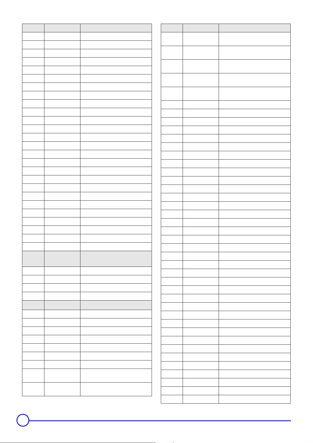
Markers Code no. Description
197 9532-0579 Feed through
198 9532-0186 Cable clamp
199 8358-8228 Top cover
200 8358-4913 3 pin AMP cable - filter
201 8358-4906 Ignition transformer cable - spark plug
202 8358-4914 Earth wire
203 8358-4915 Black wire, filter - ignition transformer
204 8358-4916 Blue wire, filter - ignition transformer
205 8350-4911 Gas line connector
206 8350-4915 Gas pressure switch connector
207 8358-8601 Ignition burner
208 9758-0449 Ignition burner injector
209 9536-1580 Ignition burner valve
210 9494-8065 Nipple N245 1/4" x 1/8"
211 9492-6030 Tee 1/4"
212 9494-6035 Nipple N280 1/4"
212 9494-8055 Nipple N241 1/4" x 1/8"
214 9536-0220 Pressure socket
215 8358-8338 Flame non-return plate - 8 sections
215 8358-8340 Flame non-return plate - 10 sections
215 8358-8342 Flame non-return plate - 12 sections
215 8358-8343 Flame non-return plate - 14 sections
215 8358-8344 Flame non-return plate - 16 sections
215 8358-8345 Flame non-return plate - 18 sections
215 8358-8346 Flame non-return plate - 20 sections
CIRCUIT SEPARATION
TRANSFORMER
761 9654-1620 Circuit separation transformer
762 8358-8737 Screws
763 8358-4922 Cable conductor
CLADDING
230 200003920 Cladding complete - 8 sections
230 200003921 Cladding complete - 10 sections
230 200003922 Cladding complete - 12 sections
230 200003923 Cladding complete - 14 sections
230 200003924 Cladding complete - 16 sections
230 200003925 Cladding complete - 18 sections
230 200003926 Cladding complete - 20 sections
231 8358-8618
231 8358-8620
Complete front cladding support - 8
sections
Complete front cladding support - 10
sections
Markers Code no. Description
231 8358-8622
231 8358-8623
231 8358-8624
231 8358-8625
231 8358-8626
232 8358-6572 Lateral panel complete left
233 8358-6573 Lateral panel complete right
234 8358-8208 Holding bracket - 8 sections
234 8358-8210 Holding bracket - 10 sections
234 8358-8212 Holding bracket - 12 sections
234 8358-8213 Holding bracket - 14 sections
234 8358-8214 Holding bracket - 16 sections
234 8358-8215 Holding bracket - 18 sections
234 8358-8216 Holding bracket - 20 sections
235 8358-0621 Painted cover - 8 sections
235 8358-0623 Painted cover - 10 sections
235 8358-0625 Painted cover - 12 sections
235 8358-0626 Painted cover - 14 sections
235 8358-0627 Painted cover - 16 sections
235 8358-0628 Painted cover - 18 sections
235 8358-0629 Painted cover - 20 sections
236 200003470 Upper front panel - 8 sections
236 200003471 Upper front panel - 10 sections
236 200003472 Upper front panel - 12 sections
236 200003473 Upper front panel - 14 sections
236 200003474 Upper front panel - 16 sections
236 200003475 Upper front panel - 18 sections
236 200003576 Upper front panel - 20 sections
237 200003513 Inside front panel - 8 sections
237 200003514 Inside front panel - 10 sections
237 200003515 Inside front panel - 12 sections
237 200003516 Inside front panel - 14 sections
237 200003517 Inside front panel - 16 sections
237 200003518 Inside front panel - 18 sections
237 200003519 Inside front panel - 20 sections
238 8358-8947 Complete lower front panel - 8 sections
238 8358-8949 Complete lower front panel - 10 sections
238 8358-8951 Complete lower front panel - 12 sections
238 8358-8952 Complete lower front panel - 14 sections
238 8358-8953 Complete lower front panel - 16 sections
238 8358-8954 Complete lower front panel - 18 sections
Complete front cladding support - 12
sections
Complete front cladding support - 14
sections
Complete front cladding support - 16
sections
Complete front cladding support - 18
sections
Complete front cladding support - 20
sections
32
Remeha Gas 460 S 06/02/06 - 300005247-001-B
Page 33

Markers Code no. Description
238 8358-8955 Complete lower front panel - 20 sections
239 8358-8938 Upper rear panel - 8 sections
239 8358-8940 Upper rear panel - 10 sections
239 8358-8942 Upper rear panel - 12 sections
239 8358-8943 Upper rear panel - 14 sections
239 8358-8944 Upper rear panel - 16 sections
239 8358-8945 Upper rear panel - 18 sections
239 8358-8946 Upper rear panel - 20 sections
240 8358-8306 Lower back panel - 8 sections
240 8358-8308 Lower back panel - 10 sections
240 8358-8310 Lower back panel - 12 sections
240 8358-8311 Lower back panel - 14 sections
240 8358-8312 Lower back panel - 16 sections
240 8358-8313 Lower back panel - 18 sections
240 8358-8314 Lower back panel - 20 sections
241 8358-6583 Additional part - 8 sections
241 8358-6585 Additional part - 10 sections
241 8358-6587 Additional part - 12 sections
241 8358-6588 Additional part - 14 sections
241 8358-6589 Additional part - 16 sections
241 8358-6590 Additional part - 18 sections
241 8358-6591 Additional part - 20 sections
242 8358-5562 10 collar kit
243 8358-8629 Housing screws packet
244 8358-8327 Deflector, rear panel
06/02/06 - 300005247-001-B Remeha Gas 460 S
33
Page 34

34
Remeha Gas 460 S 06/02/06 - 300005247-001-B
Page 35

06/02/06 - 300005247-001-B Remeha Gas 460 S
35
Page 36

NL Remeha B.V.
Postbus 32
7300 AA APELDOORN
Tel: +31 55 5496969
Fax: +31 55 5496496
Internet: nl.remeha.com
E-mail: [email protected]
GB Broag Ltd.
Remeha House
Molly Millars Lane
RG41 2QP WOKINGHAM, Berks.
Tel: +44 118 9783434
Fax: +44 118 9786977
Internet: uk.remeha.com
E-mail: [email protected]
B J.L. Mampaey BVBA
Uitbreidingstraat 54
2600 ANTWERPEN
Tel: +32 3 2307106
Fax: +32 3 2301153
Internet: www.mampaey.be
E-mail: [email protected]
B Thema S.A.
6, Avenue de l'expansion
4460 GRACE-HOLLOGNE
Tel: +32 4 2469575
Fax: +32 4 2469576
Internet: www.thema-sa.be
E-mail: [email protected]
E D.A.C. S.A.
Tomás A. Edison 29
Poligono Cogullada
50014 ZARAGOZA
Tel: +34 76 464076
Fax: +34 76 471311
Internet: www.dac.es
E-mail: [email protected]
E Norte Comercial Organización S.A.
Bereteage Bidea, 19
48180 LOIU (Vizcaya)
Tel: +34 94 471 03 33
Fax: +34 94 471 11 52
E-mail: [email protected]
IRL Euro Gas Ltd.
Unit 38, Southern Cross Business Park
Boghall Road, Bray, Co
WICKLOW
Tel: +353 12868244
Fax: +353 12861729
Internet: www.eurogas.ie
E-mail: [email protected]
H Marketbau - Remeha Kft.
Gyár u. 2.
Ipari Park
2040 BUDAÖRS
Tel: +36 23 503 980
Fax: +36 23 503 981
Internet: www.remeha.hu
E-mail: [email protected]
E Termibarna S.A.
C. Zamora 55-59
08005 BARCELONA
Tel: +34 3 3000204
Fax: +34 3 3009558
E Cuatrocesa S.A.
c) Sor Angela de La Cruz, 10
- 1º Oficina C
28020 MADRID
Tel: +34 91 658 18 88
Fax: +34 91 658 30 77
© Copyright
All technical and technological information contained in these technical instructions, as well as any
drawings and technical descriptions supplied, remain our property and shall not be multiplied without
our prior consent in writing..
Ours is a policy of continuous development. We reserve the right to alter specifications without prior
notification
.
Subject to alterations
 Loading...