

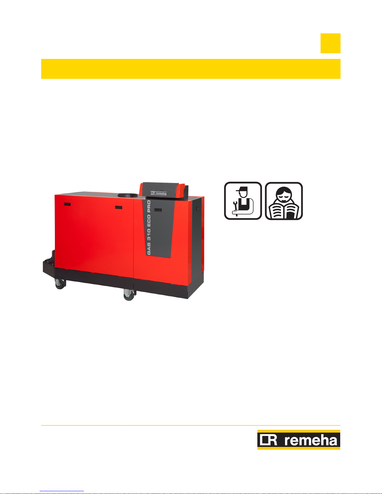
REMEHA Gas 310 ECO PRO-430, Gas 310 ECO PRO-650, Gas 310 ECO PRO-355, Gas 310 ECO PRO-575, Gas 310 ECO PRO-500 Installation, User And Service Manual
...Page 1
Great Britain
EN
Gas 310 ECO PRO Gas 610 ECO PRO
Installation, User
and Service
Manual
125467-05
Page 2

EC declaration of conformity
The device complies with the standard type described in the EG
declaration of conformity. It was manufactured and commissioned in
accordance with European directives.
The original declaration of conformity is available from the
manufacturer.
Page 3

Contents
1 Introduction ................................................................................................6
1.1 Symbols used .......................................................6
1.2 Abbreviations ........................................................6
1.3 Liabilities ...............................................................7
1.3.1 Manufacturer’s liability .............................................7
1.3.2 Installer’s liability .....................................................7
1.3.3 User’s liability ..........................................................7
2 Safety instructions and recommendations ..............................................9
2.1 Safety instructions ...............................................9
2.2 Recommendations ................................................9
3 Technical description ..............................................................................11
3.1 General description ............................................11
3.2 Homologations ....................................................11
3.2.1 Certifications .........................................................11
3.2.2 Equipment categories ...........................................12
3.2.3 Type plate .............................................................12
3.2.4 Factory test ...........................................................12
3.3 Main parts ............................................................13
3.3.1 Boiler type Gas 310 ECO PRO .............................13
3.3.2 Boiler type Gas 610 ECO PRO .............................14
3.3.3 System pump ........................................................14
3.3.4 Regulation of the water temperature .....................15
3.3.5 Protection against a shortage of water ..................15
3.3.6 Maximum temperature protection .........................15
3.3.7 Air differential pressure switch ..............................15
3.4 Technical specifications ....................................15
3.4.1 Boiler type Gas 310 ECO PRO .............................15
3.4.2 Boiler type Gas 610 ECO PRO .............................17
4 Installation ................................................................................................19
4.1 Regulations governing installation ...................19
4.2 Package list .........................................................19
4.2.1 Standard delivery ..................................................19
4.2.2 Accessories ...........................................................19
4.3 Installation options .............................................20
4.3.1 Transport ...............................................................20
160514 - 125467-05
1
Page 4

4.3.2 Location of the boiler .............................................21
4.3.3 Main dimensions ...................................................26
4.4 Hydraulic connections .......................................28
4.4.1 Flushing the system ..............................................28
4.4.2 Connection of the heating circuit ...........................28
4.4.3 Connecting the condensate discharge pipe ..........29
4.5 Gas connection ...................................................30
4.6 Connections for the air and exhaust
pipes ....................................................................30
4.6.1 Classification .........................................................31
4.6.2 Outlets ...................................................................31
4.6.3 Lengths of the air/flue gas pipes ...........................32
4.6.4 Additional Directives ..............................................35
4.6.5 Connection of the combustion gas exhaust
pipe .......................................................................35
4.6.6 Connection of the air intake pipe ...........................36
4.7 Electrical connections ........................................36
4.7.1 Control unit ............................................................37
4.7.2 Recommendations ................................................38
4.7.3 Standard control PCB ...........................................38
4.7.4 Connecting the on/off control ................................40
4.7.5 Connecting modulating controller .........................40
4.7.6 Shutdown input .....................................................40
4.7.7 Release input ........................................................41
4.7.8 System pump ........................................................41
4.7.9 PC/Laptop connection ...........................................41
4.7.10 Connection possibilities for the PCB (SCU-
S05) .......................................................................42
4.8 Electrical diagram ...............................................47
4.9 Filling the system ...............................................47
4.9.1 Water treatment ....................................................48
4.9.2 Filling the siphon ...................................................48
4.9.3 Filling the system ..................................................49
5 Commissioning ........................................................................................50
5.1 Control panel .......................................................50
5.1.1 Functions of the keys ............................................50
5.1.2 Meaning of the symbols on the display .................50
5.2 Check points before commissioning ................51
5.2.1 Preparing the boiler for commissioning .................51
5.2.2 Gas circuit .............................................................52
5.2.3 Hydraulic circuit .....................................................52
5.2.4 Connections for the air and exhaust pipes ............52
5.2.5 Electrical connections ...........................................52
5.3 Commissioning the boiler ..................................52
5.4 Gas settings ........................................................53
5.4.1 Setting the air/gas ratio (Full load) ........................54
Contents
160514 - 125467-05
2
Page 5

5.4.2 Setting the air/gas ratio (Part load) ......................55
5.5 Checks and adjustments after
commissioning ...................................................56
5.5.1 Finalizing work ......................................................56
5.6 Reading out measured values ...........................56
5.6.1 Reading the various current values .......................56
5.7 Changing the settings ........................................57
6 Switching off the boiler ............................................................................58
6.1 Installation shutdown .........................................58
6.2 Antifreeze protection ..........................................58
7 Checking and maintenance .....................................................................59
7.1 General ................................................................59
7.2 Standard checks .................................................59
7.2.1 Checking the hydraulic pressure ...........................60
7.2.2 Checking the ionization current .............................60
7.2.3 Check the water quality .........................................60
7.2.4 Checking the air supply connections and flue gas
discharge connections ..........................................60
7.2.5 Checking the gas filter for pollution .......................61
7.2.6 Checking combustion ............................................61
7.2.7 Check the air supply hose .....................................62
7.2.8 Check the dirt trap .................................................62
7.2.9 Check the air box ..................................................62
7.2.10 Check the air pressure differential switch PS ........63
7.2.11 Check the gas leakage control VPS ......................64
7.2.12 Check the minimum gas pressure switch
Gps ........................................................................66
7.3 Specific maintenance operations ......................66
7.3.1 Clean the fan and the venturi ................................67
7.3.2 Clean and inspect the non-return valve ................68
7.3.3 Replacing the ionization/ignition electrode ............68
7.3.4 Cleaning the gas filter ...........................................69
7.3.5 Cleaning the burner ...............................................70
7.3.6 Clean the burner area ...........................................70
7.3.7 Checking the heat exchanger ...............................71
7.3.8 Cleaning the condensate collector ........................72
7.3.9 Cleaning the siphon ..............................................72
7.3.10 Assembling the boiler ............................................73
7.3.11 Put the boiler back into operation ..........................73
8 Troubleshooting .......................................................................................74
8.1 Shutdowns and lock-outs ..................................74
8.1.1 General .................................................................74
8.1.2 Blocking .................................................................74
8.1.3 Lock out .................................................................74
160514 - 125467-05
3
Page 6

8.1.4 Error memory ........................................................75
9 Spare parts ................................................................................................76
9.1 General ................................................................76
10 Checklists .................................................................................................77
10.1 Checklist for commissioning .............................77
10.2 Checklist for periodic inspection and
maintenance ........................................................78
Contents
160514 - 125467-05
4
Page 7

160514 - 125467-05
5
Page 8
1 Introduction
1.1 Symbols used
In these instructions, various danger levels are employed to draw the
user’s attention to particular information. In so doing, we wish to
safeguard the user’s safety, obviate hazards and guarantee correct
operation of the appliance.
DANGER
Risk of a dangerous situation causing serious physical
injury.
WARNING
Risk of a dangerous situation causing slight physical
injury.
CAUTION
Risk of material damage.
Signals important information.
¼Signals a referral to other instructions or other pages in the
instructions.
1.2 Abbreviations
4 3CE: Collective conduit for sealed boiler
4 Central heating: Central heating
4 PCU: Primary Control Unit - PCB for managing burner operation
4 SU: Safety Unit - Safety PCB
4 PSU: Parameter Storage Unit - Parameter storage for PCBs
PCU and SU
4 SCU: Secondary Control Unit - Extended control PCB
1. Introduction
Gas 310 ECO PRO - Gas 610 ECO PRO
6
160514 - 125467-05
Page 9

1.3 Liabilities
1.3.1. Manufacturer’s liability
Our products are manufactured in compliance with the requirements
of the various applicable European Directives. They are therefore
delivered with [ marking and all relevant documentation.
In the interest of customers, we are continuously endeavouring to
make improvements in product quality. All the specifications stated in
this document are therefore subject to change without notice.
Our liability as the manufacturer may not be invoked in the following
cases:
4 Failure to abide by the instructions on using the appliance.
4 Faulty or insufficient maintenance of the appliance.
4 Failure to abide by the instructions on installing the appliance.
1.3.2. Installer’s liability
The installer is responsible for the installation and inital start up of the
appliance. The installer must respect the following instructions:
4 Read and follow the instructions given in the manuals provided
with the appliance.
4 Carry out installation in compliance with the prevailing legislation
and standards.
4 Perform the initial start up and carry out any checks necessary.
4 Explain the installation to the user.
4 If a maintenance is necessary, warn the user of the obligation to
check the appliance and maintain it in good working order.
4 Give all the instruction manuals to the user.
1.3.3. User’s liability
To guarantee optimum operation of the appliance, the user must
respect the following instructions:
4 Read and follow the instructions given in the manuals provided
with the appliance.
4 Call on qualified professionals to carry out installation and initial
start up.
4 Get your installer to explain your installation to you.
4 Have the required checks and services done by a qualified
professional.
4 Keep the instruction manuals in good condition close to the
appliance.
Gas 310 ECO PRO - Gas 610 ECO PRO
1. Introduction
160514 - 125467-05
7
Page 10

This appliance is not intended to be used by persons (including
children) whose physcial, sensory or mental capacity is impaired or
persons with no experience or knowledge, unless they have the
benefit, through the intermediary of a person responsible for their
safety, of supervision or prior instructions regarding use of the
appliance. Care should be taken to ensure that children do not play
with the appliance.
If the mains lead is damaged it must be replaced by the original
manufacturer, the manufacturer’s dealer or another suitably skilled
person to prevent hazardous situations.
1. Introduction Gas 310 ECO PRO - Gas 610 ECO PRO
8
160514 - 125467-05
Page 11
2 Safety instructions and
recommendations
2.1 Safety instructions
DANGER
If you smell gas:
1. Do not use a naked flame, do not smoke, do not
operate electrical contacts or switches ( doorbell,
light, motor, lift, etc..).
2. Shut off the gas supply.
3. Open the windows.
4. Report any leaks immediately.
5. Trace possible leaks and seal them immediately.
6. If the gas leak is before the gas meter, contact the
gas supplier.
DANGER
If you smell flue gases:
1. Switch the appliance off.
2. Open the windows.
3. Report any leaks immediately.
4. Trace possible leaks and seal them immediately.
2.2 Recommendations
WARNING
4 Installation and maintenance of the boiler must be
carried out by a qualified professional in compliance
with prevailing local and national regulations.
4 When working on the boiler, always disconnect the
boiler from the mains and close the main gas inlet
valve.
4 After maintenance or repair work, check all
installations to ensure that there are no leaks.
CAUTION
The boiler must be installed in a frost-free environment.
Store this document in the document wallet on the inside
of the boiler casing (Underneath the instrument panel).
Gas 310 ECO PRO - Gas 610 ECO PRO 2. Safety instructions and recommendations
160514 - 125467-05
9
Page 12

Casing components
Only remove the casing for maintenance and repair operations. Put
the casing back in place after maintenance and repair operations.
Instructions stickers
The instructions and warnings affixed to the appliance must never be
removed or covered and must remain legible during the entire lifespan
of the appliance. Immediately replace damaged or illegible
instructions and warning stickers.
Modifications
Modifications may only be made to the boiler after the written
permission of Remeha to do so.
2. Safety instructions and recommendations Gas 310 ECO PRO - Gas 610 ECO PRO
10
160514 - 125467-05
Page 13

3 Technical description
3.1 General description
Floor-standing high efficiency gas boiler
4 High efficiency heating.
4 Low pollutant emissions.
4 Heat exchanger made of cast aluminium sections.
4 Transport wheels as standard.
4 Left or right-hand version of the water and flue gas side
connections possible.
4 Separable for assembly in boiler room.
4 HMI Gas 310/610 ECO PRO control panel.
Boiler type:
4 Type Gas 310 ECO PRO-285
4 Type Gas 310 ECO PRO-355
4 Type Gas 310 ECO PRO-430
4 Type Gas 310 ECO PRO-500
4 Type Gas 310 ECO PRO-575
4 Type Gas 310 ECO PRO-650
Boiler type:
4 Type Gas 610 ECO PRO-570
4 Type Gas 610 ECO PRO-710
4 Type Gas 610 ECO PRO-860
4 Type Gas 610 ECO PRO-1000
4 Type Gas 610 ECO PRO-1150
4 Type Gas 610 ECO PRO-1300
3.2 Homologations
3.2.1. Certifications
CE identification no
PIN 0063CL3613
NOx classification
5 (EN 15420)
Type of connection
(Flue gas outlet)
B23, B
23P
, C33, C53, C63, C83, C
93
Gas 310 ECO PRO - Gas 610 ECO PRO 3. Technical description
160514 - 125467-05
11
Page 14
3.2.2. Equipment categories
Gas category Gas type Connection pressure (mbar)
I
2H
Gas H (G20) 20
The boiler is preset in the factory to operate on natural gas G20 (Gas
H).
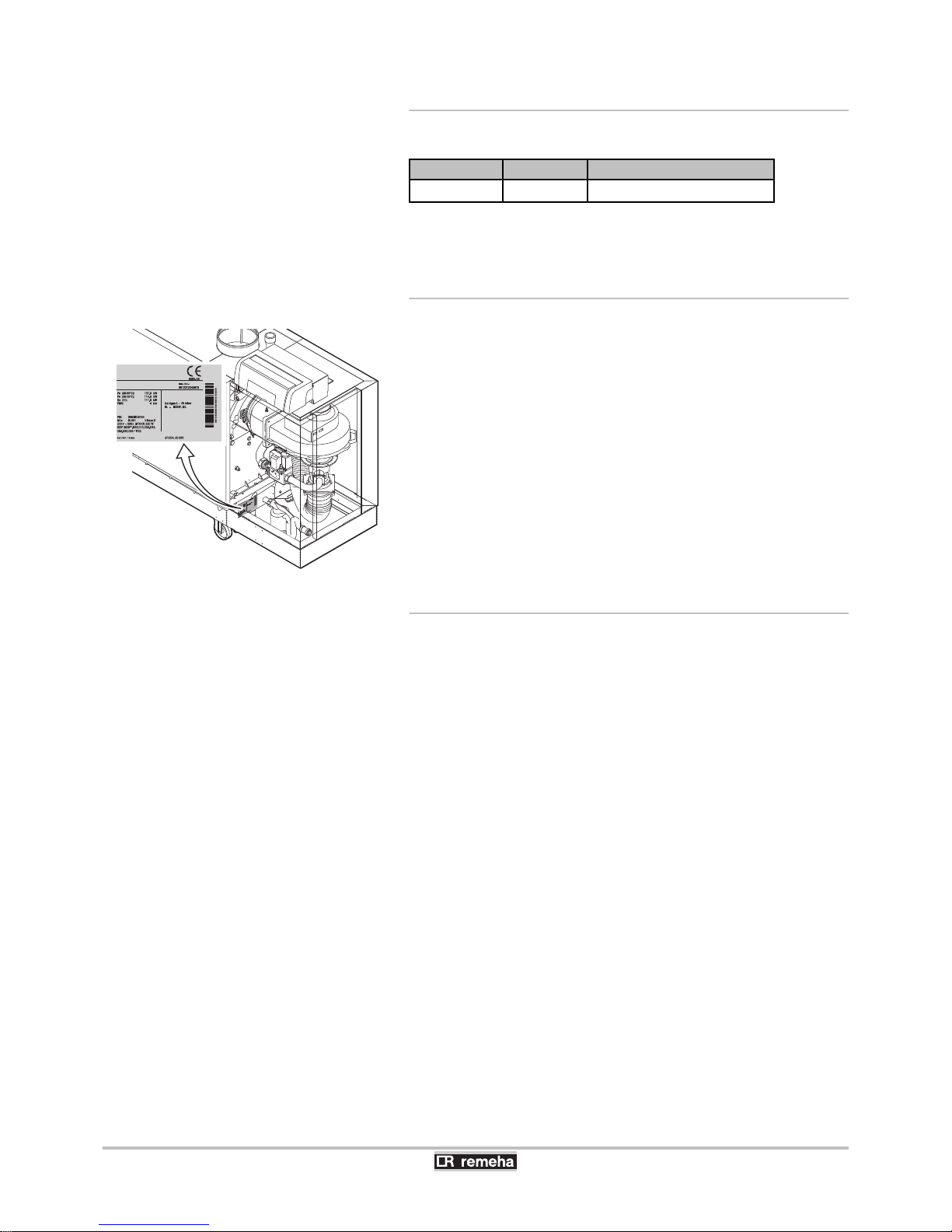
3.2.3. Type plate
The identification plate is located behind the boiler casing on the
frame, near the syphon connection. It contains the boiler serial
number and important boiler specifications, such as the model and
the gas category.
3.2.4. Factory test
Before leaving the factory, each boiler is set for optimum performance
and tested to check the following items:
4 Electrical safety
4 Adjustment (CO2)
4 Water tightness
4 Gas tightness
4 Parameter settings
T003475-F
3. Technical description Gas 310 ECO PRO - Gas 610 ECO PRO
12
160514 - 125467-05
Page 15
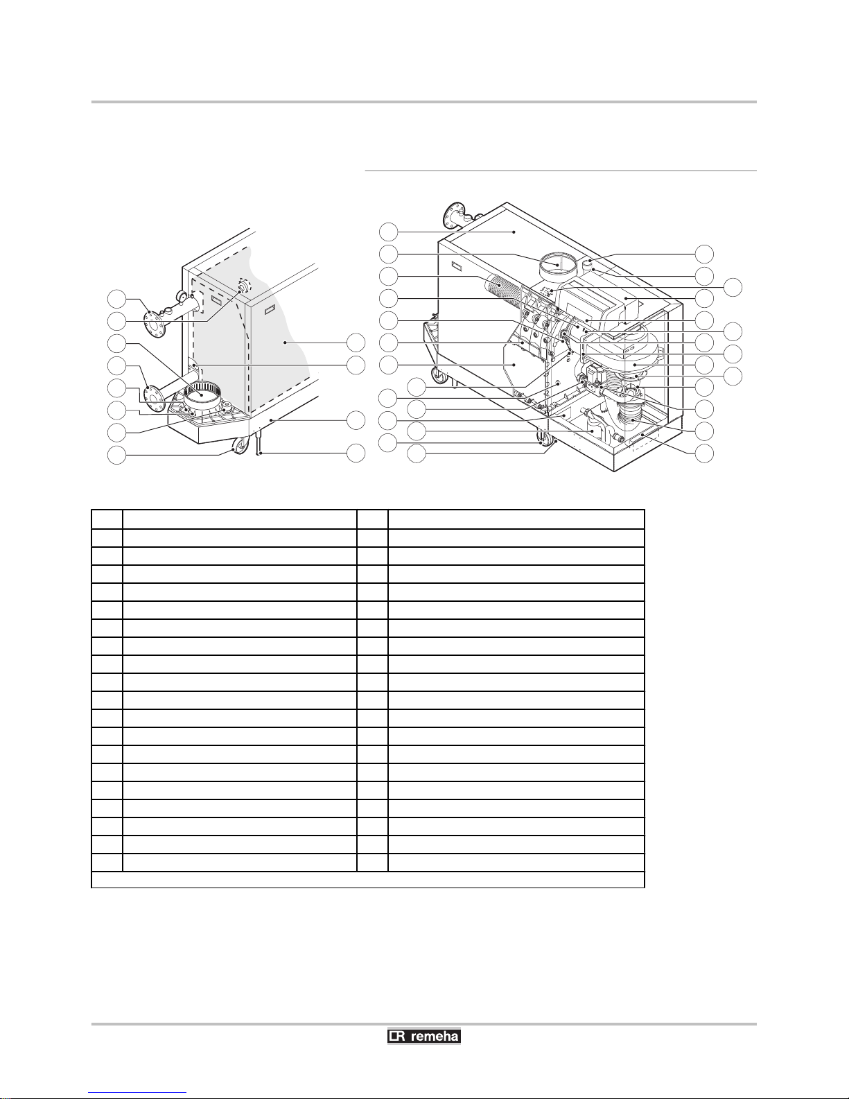
3.3 Main parts
3.3.1. Boiler type Gas 310 ECO PRO
T004014-E
2
1
3
4
5
6
7
8
27
40
28
29
30
32
34
31
33
35
36
37
38
39
11
12
14
13
15
16
17
18
19
20
22
24
26
21
23
25
10
9
1
Flow connection
(1)
21
Return sensor
2
Air differential pressure switch
22
Gas filter
3
Flue gas discharge pipe
23
Type plate
4
Return connection
24
Siphon
5
Outlet for measuring combustion gases
25
Transport wheels
6
Flue gas thermostat (Accessory)
26
Jacking bolt
7
Condensate collector sealant cap
27
Gas connection
8
Pivoting castor
28
Gas pressure measurement point
9
Jacking bolt
29
Control panel
10
Base frame
30
Location for optional features or a control unit
11
Second return connection (Accessory)
31
Pressure measurement point
12
Heat exchanger insulation kit (Accessory)
32
Sight glass
13
Boiler casing
33
Non-return valve
14
Air inlet
34
Fan
15
Burner
35
Extension piece
16
Adapter
36
Venturi
17
Ignition/ionization electrode
37
Gas block
18
Heat exchanger
38
Air inlet hose
19
Inspection hatch
39
Document holder
20
Heat exchanger sensor
40
Ignition transformer
(1) ¼For more details about the devices in the flow pipe, please see "Connection of the heating circuit", page 28
Gas 310 ECO PRO - Gas 610 ECO PRO 3. Technical description
160514 - 125467-05
13
Page 16
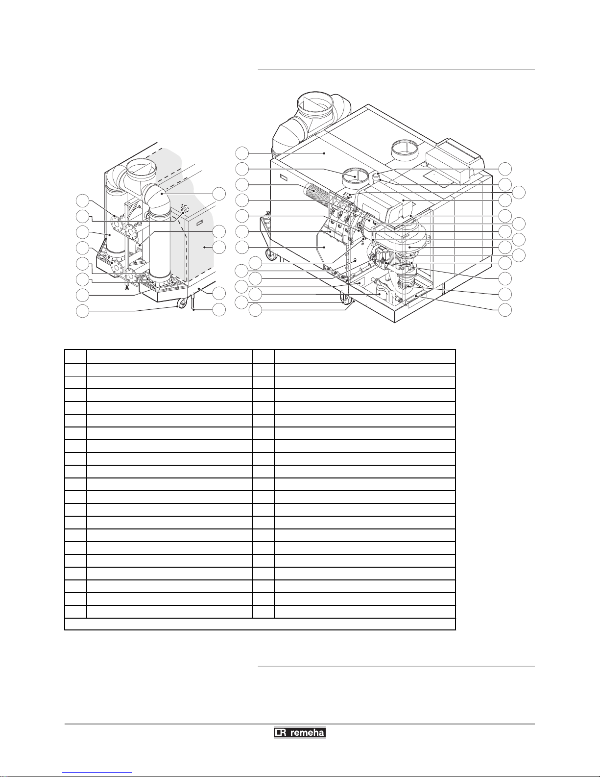
3.3.2. Boiler type Gas 610 ECO PRO
T004015-G
1
3
4
5
2
6
7
8
27
28
29
30
32
34
31
33
35
36
14
13
15
16
17
18
19
20
22
24
26
21
23
25
10
41
11
12
9
37
38
39
40
1
Flow connection
(1)
21
Return sensor
2
Air differential pressure switch
22
Gas filter
3
Flue gas discharge pipe
23
Type plate
4
Return connection
24
Siphon
5
Outlet for measuring combustion gases
25
Transport wheels
6
Flue gas thermostat (Accessory)
26
Jacking bolt
7
Condensate collector sealant cap
27
Gas connection
8
Pivoting castor
28
Gas pressure measurement point
9
Jacking bolt
29
Control panel
10
Base frame
30
Location for optional features or a control unit
11
Heat exchanger insulation kit (Accessory)
31
Pressure measurement point
12
Flue gas collector
32
Sight glass
13
Boiler casing
33
Non-return valve
14
Air inlet
34
Fan
15
Burner
35
Extension piece
16
Adapter
36
Venturi
17
Ignition/ionization electrode
37
Gas block
18
Heat exchanger
38
Air inlet hose
19
Inspection hatch
39
Document holder
20
Heat exchanger sensor
40
Ignition transformer
41
Second return connection (Accessory)
(1) ¼For more details about the devices in the flow pipe, please see "Connection of the heating circuit", page 28
3.3.3. System pump
The boiler does not have a built-in pump. A system pump can be
installed on the connector of the standard control PCB. This can be
an on/off pump or a modulating pump (with 0 - 10 V control).
3. Technical description
Gas 310 ECO PRO - Gas 610 ECO PRO
14
160514 - 125467-05
Page 17

¼For more information on controlling a modulating pump, See
paragraph: "Electrical connections", page 36.
Parameters p43 and p44 are used to modify the pump settings.
¼See the Installation and service manual HMI GAS 310/610 ECO
PRO for comprehensive operating instructions. This includes
information about changing and reading parameters, the meaning of
fault codes and deleting the failure memory.
3.3.4. Regulation of the water temperature
The boiler is equipped with electronic temperature control based on
flow, return, and boiler block temperature sensors. The flow
temperature can be set between 20°C and 90°C. The boiler reduces
its power when the set outlet-temperature is attained. The cutout
temperature is the set heating outlet-temperature + 5 °C.
3.3.5. Protection against a shortage of water
The boiler is fitted with a safety device to prevent the shortage of water
based on temperature measurements (Temperature difference
between flow and return). If ΔT = 25 K is reached (factory setting),
the boiler reduces its output by modulating to remain in operation as
long as possible. If ΔT ≥ 25 K the boiler goes into part load. If ΔT >
25 + 5 K the boiler goes into a normal control stop (blocking).
3.3.6. Maximum temperature protection
The maximum protection switches the boiler off if the water
temperature is too high (110°C) and locks it on the control box (Fixed
value, cannot be modified). Once the fault has been rectified, the
boiler can be reset by pressing the J button for 2 seconds.
3.3.7. Air differential pressure switch
Before a start and when the boiler is in operation, the air pressure
differential switch PS measures the difference in pressure between
the measuring points at the rear of the heat exchanger p+ and the air
box p-. If the pressure difference is greater than 6 mbar, then the boiler
will lock out. Once the fault has been rectified, the boiler can be reset
by pressing the J button for 2 seconds.
3.4 Technical specifications
3.4.1. Boiler type Gas 310 ECO PRO
Gas 310 ECO PRO - Gas 610 ECO PRO
3. Technical description
160514 - 125467-05
15
Page 18
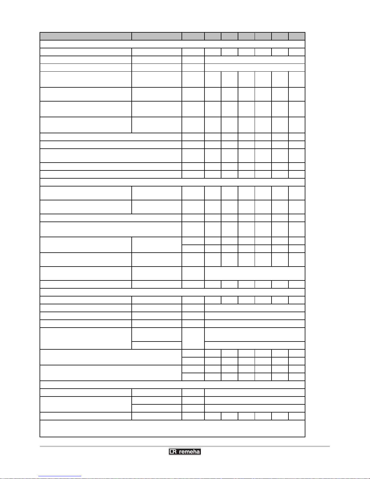
Boiler type GAS 310 ECO PRO Unit 285 355 430 500 575 650
General
Number of sections - - 5 6 7 8 9 10
EC indentification no. PIN
0063CL3613
Input control Adjustable
Modulating, Start/Stop, 0 - 10 V
Nominal output (Pn)
(80/60 °C)
minimum
maximum
(1)
kW
51
261653277939592461
106
530
119
601
Nominal output (Pn)
(50/30 °C)
maximum
(1)
kW 279 350 425 497 574 651
Nominal input(Qn)
(Hs)
minimum
maximum
(1)
kW
60
2957536996445
105
520
121
598
135
677
Nominal input (Qn)
(Hi)
minimum
maximum
(1)
kW
54
266683338240295469
109
539
122
610
Full load water efficiency (Hi) (80/60 °C) % 98.0 98.1 98.2 98.3 98.4 98.5
Full load water efficiency (Hi) (50/30 °C) % 104.8 105.2 105.6 106.0 106.4 106.8
Low load water efficiency (Hi)
(Tr = 60 °C)
% 94.7 95.3 95.8 96.3 96.8 97.3
Annual efficiency (DIN 4702, Part 8) % 109.6 109.5 109.4 109.3 109.2 109.1
Part load efficiency 92/42 EEG (Tr = 30 °C) % 109.2 109.0 108.8 108.6 108.3 108.1
Data on the gases and combustion gases
Gas consumption G20 (Gas H)
minimum
maximum
m3/h
5.7
28.1
7.2
35.2
8.7
42.5
10.1
49.6
11.5
57.0
12.9
64.6
Gas inlet pressure G20 (Gas H)
minimum
maximum
mbar
1730173017
10017100171001730
Flue gas losses % 2.3 2.3 2.3 2.3 2.3 2.3
NOx-Emission per year (BREEAM)
(EN 15420)
mg/kWh 33 35 32 29 36 26
Maintenance consumption (EN15420)
(Without heat exchanger insulation kit)
(∆T = 30 K)
(2)
W 571 591 611 630 650 670
% 0.21 0.18 0.15 0.13 0.12 0.11
Mass flue gas flow rate
minimum
maximum
kg/h
91
448
114
560
138
676
160
789
183
907
205
1026
Flue gas temperature
minimum
maximum
°C
30
80
Maximum residual fan duty for flue gas
Pa 130 120 130 150 150 150
Characteristics of the heating circuit
Water content - l 49 60 71 82 93 104
Water operating pressure minimum bar 0.8
Water operating pressure (PMS) maximum bar 7
Water temperature maximum °C 110
Operating temperature
minimum
maximum
°C
20
90
Factory setting 80
Water resistance (∆T = 20K)
mbar 113 110 120 110 125 130
kPa 11.3 11 12 11 12.5 13.0
Water resistance (∆T = 11K)
mbar 374 364 397 364 413 435
kPa 37.4 36.4 39.7 36.4 41.3 43.5
Electrical characteristics
Power supply voltage
VAC/Hz 230/50
Fuse (230 VAC)
F2 Circuit-breaker AT 10
F1 control PCB AT 2
Power consumption - Full load maximum W 279 334 426 543 763 723
(1) Factory setting
(2) ∆T = Boiler temp - Ambient temperature
(3) For a room sealed operation
3. Technical description Gas 310 ECO PRO - Gas 610 ECO PRO
16
160514 - 125467-05
Page 19
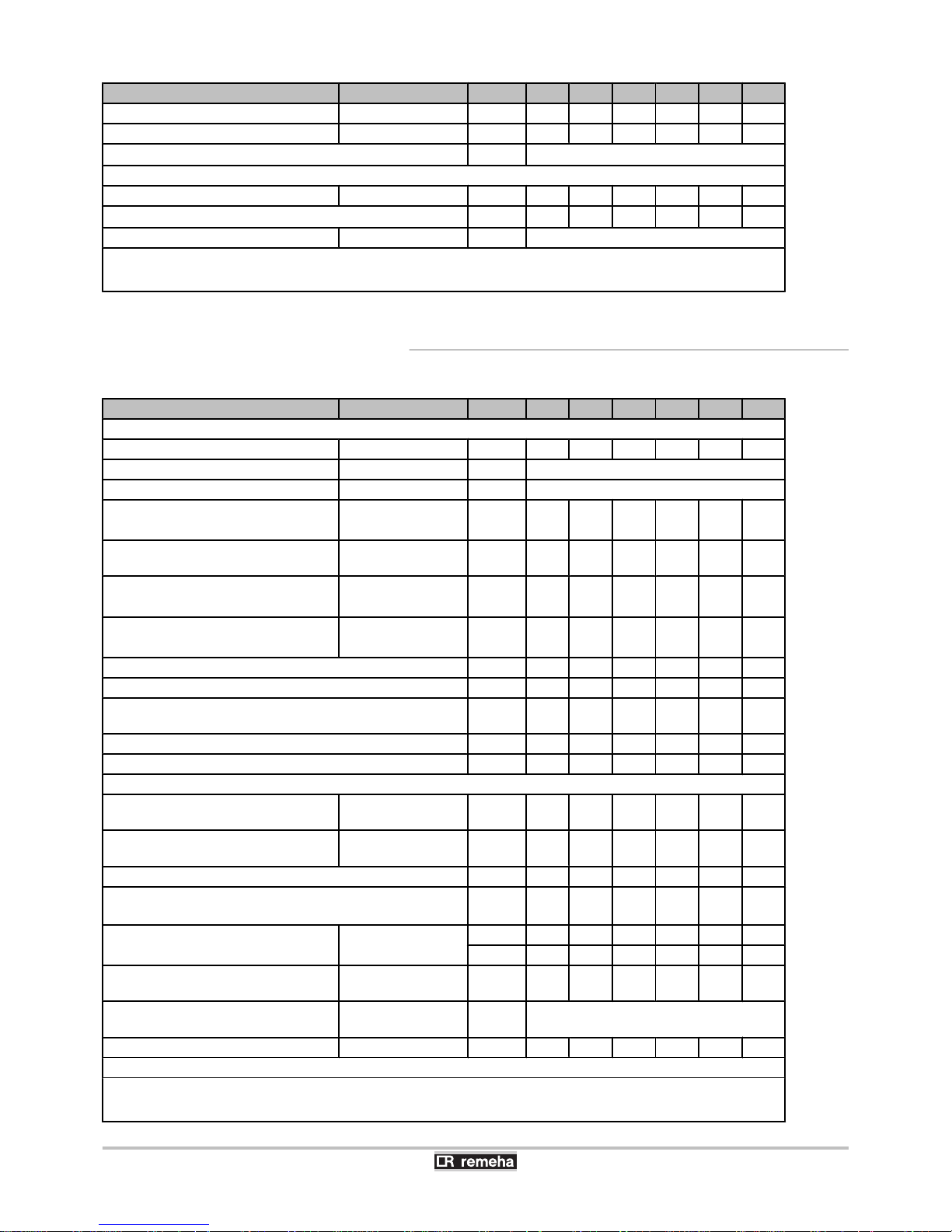
Boiler type GAS 310 ECO PRO Unit 285 355 430 500 575 650
Power consumption - Part load maximum W 46 46 58 61 62 55
Power consumption - Standby maximum W 6 6 6 6 6 7
Electrical protection index IP
X1B
(3)
Other characteristics
Weight (empty) Total kg 364 398 433 495 531 568
Acoustic level at 1 metre
(3)
dB(A) 61 61 65 65 65 65
Ambient temperature maximum °C 40
(1) Factory setting
(2) ∆T = Boiler temp - Ambient temperature
(3) For a room sealed operation
3.4.2. Boiler type Gas 610 ECO PRO
Boiler type
GAS 610 ECO PRO Unit 570 710 860 1000 1150 1300
General
Number of sections - - 2x5 2x6 2x7 2x8 2x9 2x10
EC indentification no. PIN
0063CL3613
Input control Adjustable
Modulating, Start/Stop, 0 - 10 V
Nominal output (Pn)
(80/60 °C)
minimum
maximum
(1)
kW
69
52287654
123
790
122
922
148
1060
158
1202
Nominal output (Pn)
(50/30 °C)
maximum
(1)
kW 558 700 850 994 1148 1303
Nominal input(Qn)
(Hs)
minimum
maximum
(1)
kW
80
590
101
738
142
890
141
1040
170
1196
180
1354
Nominal input (Qn)
(Hi)
minimum
maximum
(1)
kW
72
53291666
128
804
127
938
170
1078
162
1220
Full load water efficiency (Hi) (80/60 °C) % 98.0 98.1 98.2 98.3 98.4 98.5
Full load water efficiency (Hi) (50/30 °C) % 104.8 105.2 105.6 106.0 106.4 106.8
Low load water efficiency (Hi)
(Tr = 60 °C)
% 94.7 95.3 95.8 96.3 96.8 97.3
Annual efficiency (DIN 4702, Part 8) % 109.6 109.5 109.4 109.3 109.2 109.1
Part load efficiency 92/42 EEG (Tr = 30 °C) % 109.2 109.0 108.8 108.6 108.3 108.1
Data on the gases and combustion gases
Gas consumption G20 (Gas H)
minimum
maximum
m3/h
7.6
56.2
9.6
70.4
13.5
85.0
13.4
99.2
16.2
114.0
17.2
129.2
Gas inlet pressure G20 (Gas H)
minimum
maximum
mbar
1730173017
10017100171001730
Flue gas losses % 2.3 2.3 2.3 2.3 2.3 2.3
NOx-Emission per year (BREEAM)
(EN 15420)
mg/kWh 33 35 32 29 36 26
Maintenance consumption (EN15420)
(Without heat exchanger insulation kit)
(∆T = 30 K)
(2)
W 1142 1182 1222 1260 1300 1340
% 0.21 0.18 0.15 0.13 0.12 0.11
Mass flue gas flow rate
minimum
maximum
kg/h
182
896
228
1120
276
1352
320
1578
366
1814
410
2052
Flue gas temperature
minimum
maximum
°C
30
80
Maximum residual fan duty for flue gas
Pa 130 120 130 130 130 150
Characteristics of the heating circuit
(1) Factory setting
(2) ∆T = Boiler temp - Ambient temperature
(3) For a room sealed operation
Gas 310 ECO PRO - Gas 610 ECO PRO 3. Technical description
160514 - 125467-05
17
Page 20
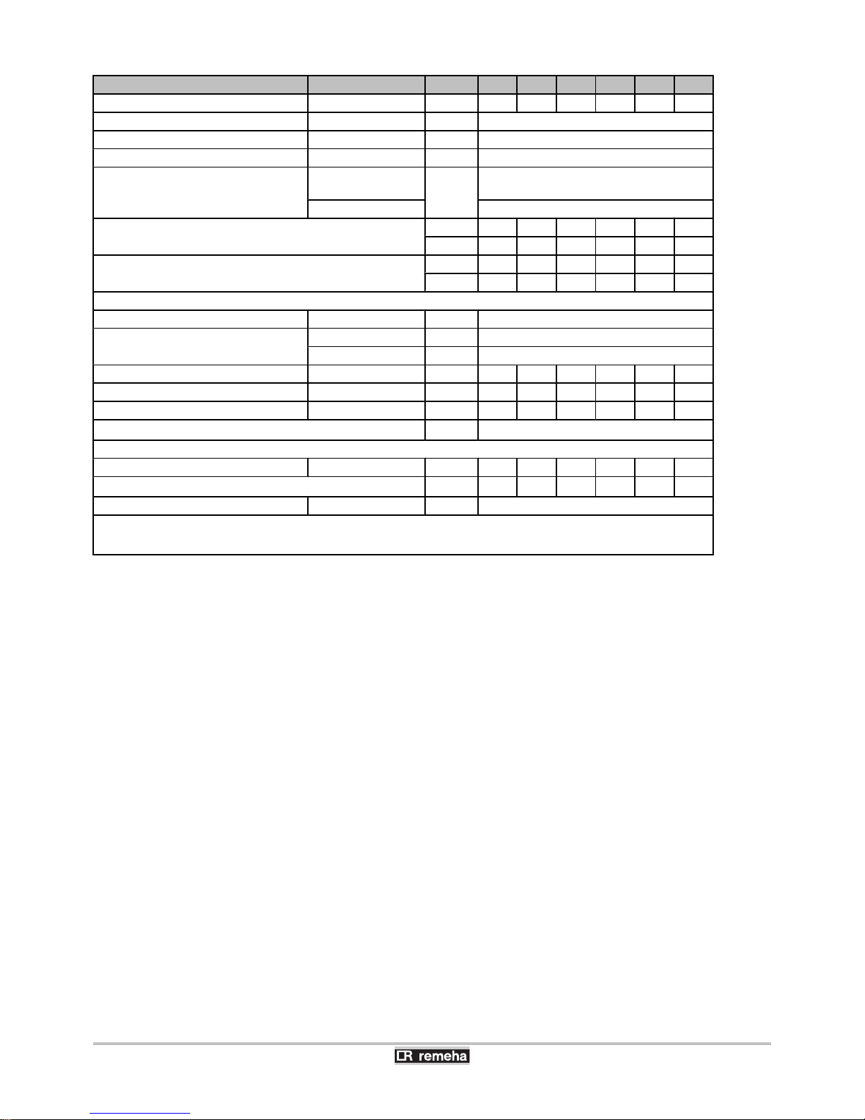
Boiler type GAS 610 ECO PRO Unit 570 710 860 1000 1150 1300
Water content - l 98 120 142 164 186 208
Water operating pressure minimum bar 0.8
Water operating pressure (PMS) maximum bar 7
Water temperature maximum °C 110
Operating temperature
minimum
maximum
°C
20
90
Factory setting 80
Water resistance (∆T = 20K)
mbar 113 110 120 110 125 130
kPa 11.3 11 12 11 12.5 13
Water resistance (∆T = 11K)
mbar 374 364 397 364 413 435
kPa 37.4 36.4 39.7 36.4 41.3 43.5
Electrical characteristics
Power supply voltage
VAC/Hz 230/50
Fuse (230 VAC)
F2 Circuit-breaker AT 10
F1 control PCB AT 2
Power consumption - Full load maximum W 558 668 852 1086 1526 1446
Power consumption - Part load maximum W 92 92 116 122 124 110
Power consumption - Standby maximum W 12 12 12 12 12 14
Electrical protection index IP
X1B
(3)
Other characteristics
Weight (empty) Total kg 707 771 837 957 1025 1095
Acoustic level at 1 metre
(3)
dB(A) 64 64 68 68 68 68
Ambient temperature maximum °C 40
(1) Factory setting
(2) ∆T = Boiler temp - Ambient temperature
(3) For a room sealed operation
3. Technical description Gas 310 ECO PRO - Gas 610 ECO PRO
18
160514 - 125467-05
Page 21
4 Installation
4.1 Regulations governing installation
WARNING
Installation of the appliance must be done by a qualified
engineer in accordance with prevailing local and national
regulations. The engineer must be Gas Safe registered
and have the correct ACS qualifications.
4.2 Package list
4.2.1. Standard delivery
4 The boiler
4 Complete siphon
4 Filling and drainage valve
4 Gas filter
4 Installation, User and Service Manual
4 Water quality instructions
4.2.2. Accessories
Only use the original or recommended accessories.
Description
Modulating cascade controller iSense Pro Gas valve leak proving system VPS
Modulating cascade controller Celcia MC4 Safety pressure sensitive switch
C-mix regulator Condensates neutralisation station
Modulating controller iSense Air supply collector (For a room sealed operation)
Outside temperature sensor (AF 60) Combined roof outlet 200/300 mm
Circulating pump replacement pipe Combined roof outlet 250/350 mm
Second return connection Parallel roof feed-through 350 mm
Heat exchanger insulation kit Air supply filter
Exchanger cleaning tool (lenghth 560 mm) Combustion air/flue gas adapter 250 - 200 mm
Gas main cock Combustion air/flue gas adapter Gas 310 ECO - Gas 310 ECO PRO
Recom communication kit Flue gas collector(250/350 mm) (base frame included)
Flue gas thermostat (Switch temperature 110ºC) Air supply filter box for closed configuration
Pressure switch minimum GPS
Gas 310 ECO PRO - Gas 610 ECO PRO 4. Installation
160514 - 125467-05
19
Page 22
4.3 Installation options
4.3.1. Transport
For Gas 610 ECO PRO boilers: The features and
instructions described are for each boiler module.
Boiler type
Gas 310 ECO PRO
L (mm)
285
1920355
430
500
2230575
650
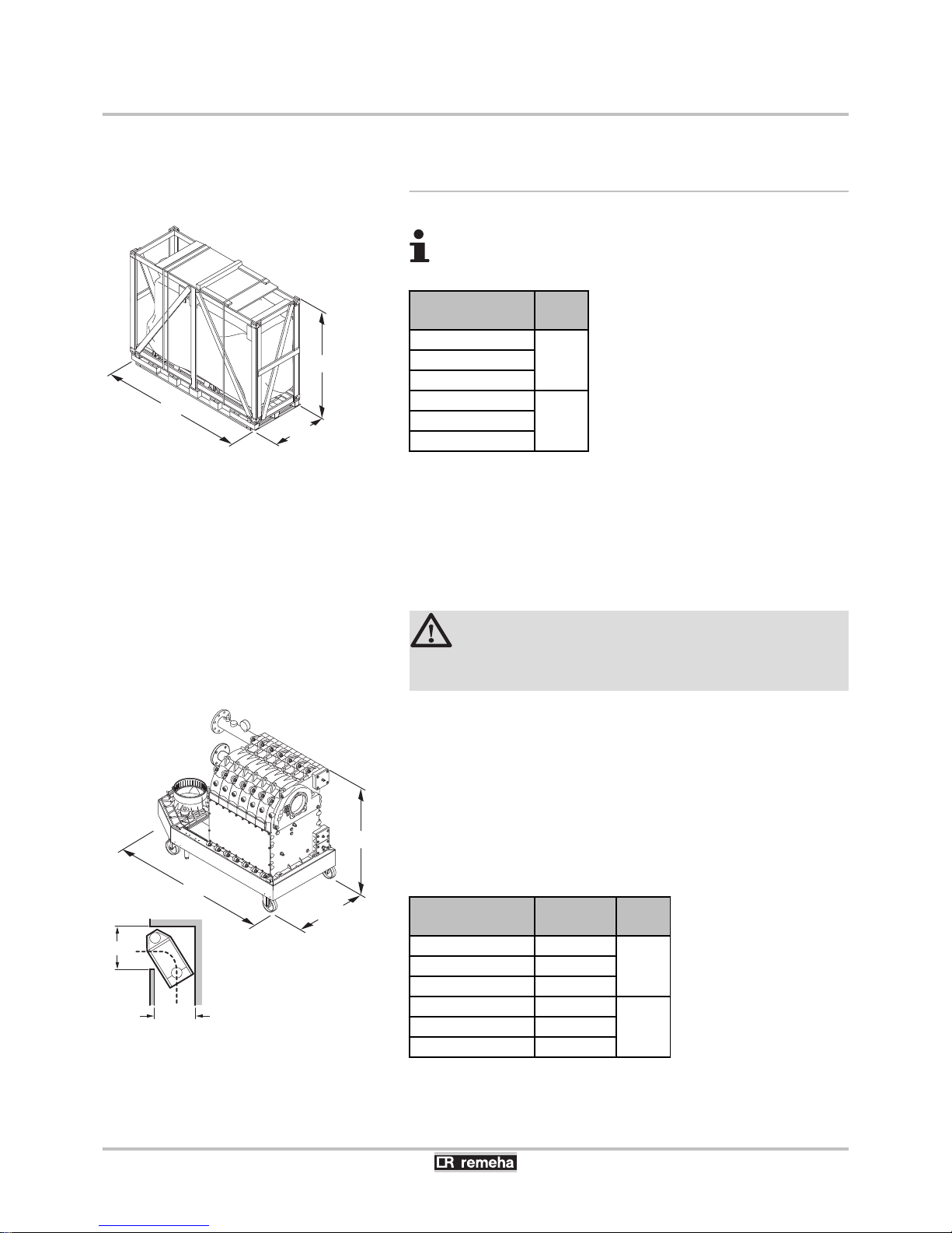
The boiler is supplied fully assembled on a pallet. See the diagram
and table for the dimensions. The base of the packaging is a pallet
80 cm wide. This means that the crate can be transported with a pallet
truck or four-wheel transport boards. Without the packaging, the
boiler is 720 mm wide (700 mm without casing) and the boiler will fit
through standard doors. The boiler has integrated wheels, so that it
can easily be moved around once the packaging has been
removed.
CAUTION
The wheels are designed for transport purposes only and
not for use when the boiler is in its final position.
If required for internal transport, the boiler can be dismantled into
smaller parts for transport. The boiler can be stripped of:
4 Casing components
4 Gas/air components
4 The frame section on the instrument panel side
See the diagram and table for the dimensions of the largest remaining
transport part (Frame section with heat exchanger and water
connections).
Boiler type
Gas 310 ECO PRO
Weight (kg) L (mm)
285 249
1160355 283
430 317
500 356
1469575 390
650 424
¼For information on fitting the parts, refer to the assembly
instructions delivered with the boiler.
T003980-C
1789
800
L
T003676-B
1107
1000
700
L
1000
4. Installation
Gas 310 ECO PRO - Gas 610 ECO PRO
20
160514 - 125467-05
Page 23
4.3.2. Location of the boiler
n
Boiler type Gas 310 ECO PRO
L
Left version
R
Right version
I
Inspection hatch (Service side)
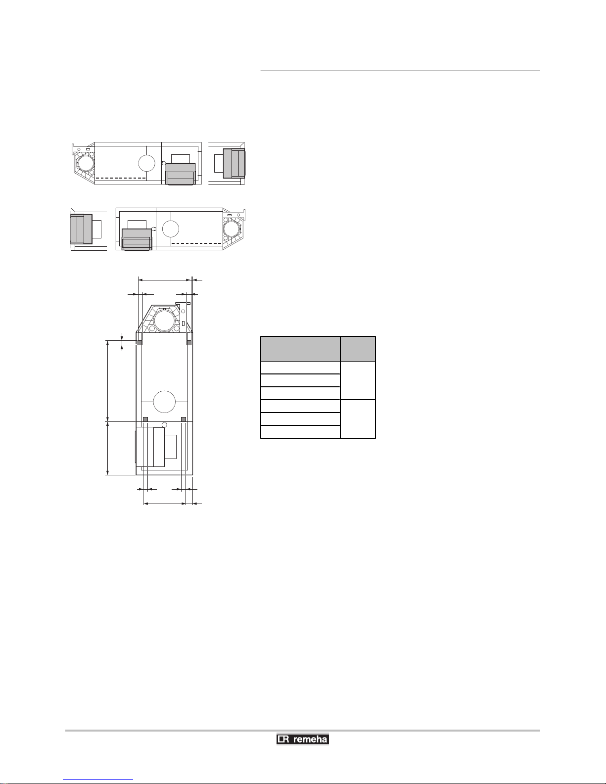
The service side with the inspection hatch on the heat exchanger is
considered to be the front of the boiler. The boiler is available in both
a ’left-hand’ and ’right-hand’ version. This means that the hydraulic
connections and the flue gas discharge are situated on either the left
or the right-hand side of the boiler. The control panel is on the front
as standard, but can easily be rotated so that it is on the short side.
To make the boiler level and to raise the wheels off the floor, the
adjustment bolts must be used. Turn the adjustment bolts out as soon
as the boiler is placed in the correct position. The picture shows the
support surface of the boiler (This is the position of the adjustment
bolts).
Boiler type
Gas 310 ECO PRO
A (mm)
285
723355
430
500
1032575
650
T003785-C
L
R
I
I
T003474-B
55 55
55 55
663 21,5
531 87,5
673
55
A
Gas 310 ECO PRO - Gas 610 ECO PRO 4. Installation
160514 - 125467-05
21
Page 24
T003499-C
C1 C300 300
C
C + 600
800*
C + 1100*
300300
600
C + C1 + 2200*
C + C1 + 1200
800* 800*
720
1670
800 150
720 720
3190
800 800150
720
1670
800 150
C
C + 600
800*
C + 1100*
300300
* =
Spacing required if this is operating side.
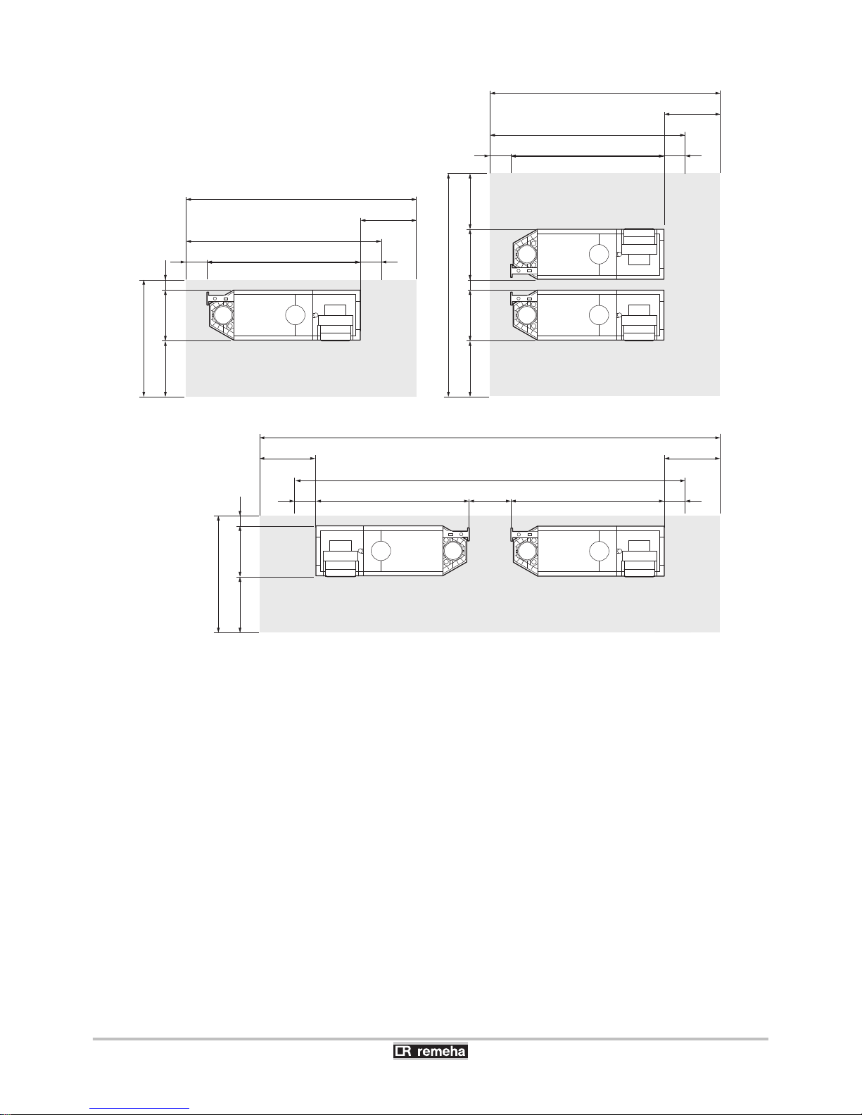
¼For the dimensions of C/C1, see paragraph: "Main
dimensions", page 26
A technical clearance of at least 80 cm is required at the front (service
side) of the boiler. However, we recommend that the clearance is at
least 100 cm. We recommend a clearance of at least 40 cm above
the boiler (If the air supply filter is used, there must be a clearance of
at least 65 cm). A minimum of 30 cm is required on the side of the
flue gas discharge, and a minimum of 30 cm is also required on the
other side (or 80 cm, if this is operating side).
4. Installation
Gas 310 ECO PRO - Gas 610 ECO PRO
22
160514 - 125467-05
Page 25
n
Boiler type Gas 610 ECO PRO
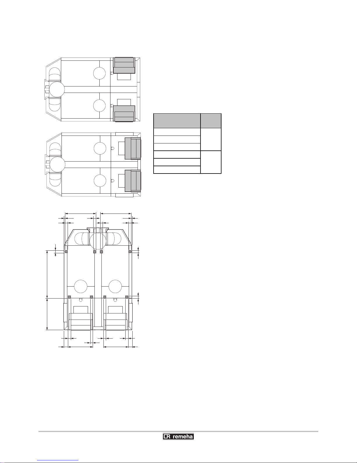
The boiler is not available with a choice between ’left-hand’ and ’righthand’ versions. The control panel is on the front as standard, but can
easily be rotated so that it is on the short side.
To make the boiler level and to raise the wheels off the floor, the
adjustment bolts must be used. Turn the adjustment bolts out as soon
as the boiler is placed in the correct position. The picture shows the
support surface of the boiler (This is the position of the adjustment
bolts).
Boiler type
Gas 610 ECO PRO
A (mm)
570
723710
860
1000
10321150
1300
T003784-C
T003767-D
5555
55
55
21,5
21,5
87,5531
663663
53187,5
673
A
55
55
55
55
55
55
55
Gas 310 ECO PRO - Gas 610 ECO PRO 4. Installation
160514 - 125467-05
23
Page 26

T003768-F
C
C
300
300
C
C + 600
800
C + 1100
300300
600
E
D
800
800
1450
1525
3050
800 800
1450
3050
800 800
¼For the dimensions of C, see paragraph: "Main dimensions",
page 26.
A technical clearance of at least 80 cm is required at the front (service
side) of the boiler. However, we recommend that the clearance is at
least 100 cm. We recommend a clearance of at least 40 cm above
the boiler (If the air supply filter is used, there must be a clearance of
at least 65 cm). A minimum of 30 cm is required on the side of the
flue gas discharge, and a minimum of 30 cm is also required on the
other side (or 80 cm, if this is operating side).
4. Installation
Gas 310 ECO PRO - Gas 610 ECO PRO
24
160514 - 125467-05
Page 27
n
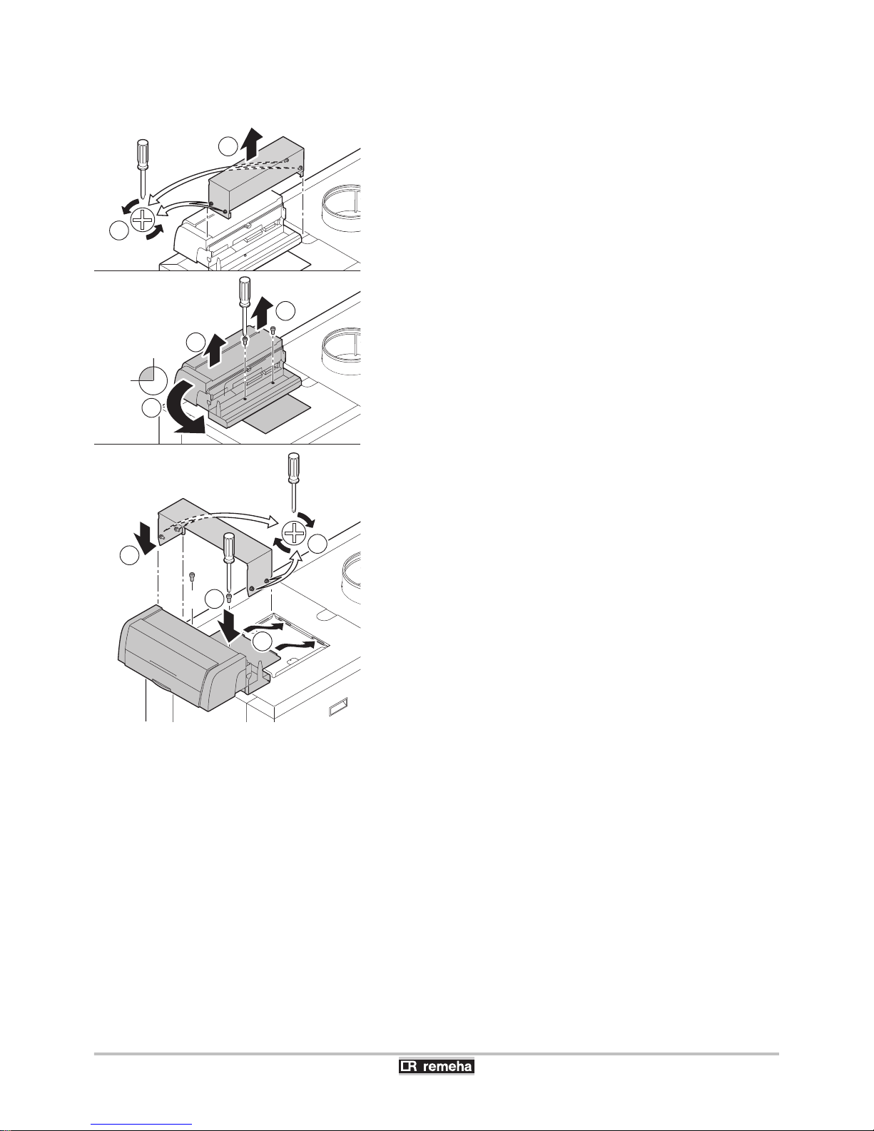
Rotate instrument panel
The control panel is on the front as standard, but can easily be rotated
so that it is on the short side.
1. Unscrew the 4 lateral holding screws in the control panel.
2. Remove the protective cover.
3. Unscrew the 2 bottom plate screws.
4. Lift up the instrument panel with the bottom plate.
5. Turn the instrument panel and the bottom plate into position on the
short side.
6. Slide the lips of the bottom plate into the appropriate slots.
7. Tighten the 2 bottom plate screws.
8. Refit the protective cover.
9. Screw the 4 lateral holding screws back in.
T004028-E
3 2x
4
90º
5
6
72x
8
9
1
2
Gas 310 ECO PRO - Gas 610 ECO PRO 4. Installation
160514 - 125467-05
25
Page 28
4.3.3. Main dimensions
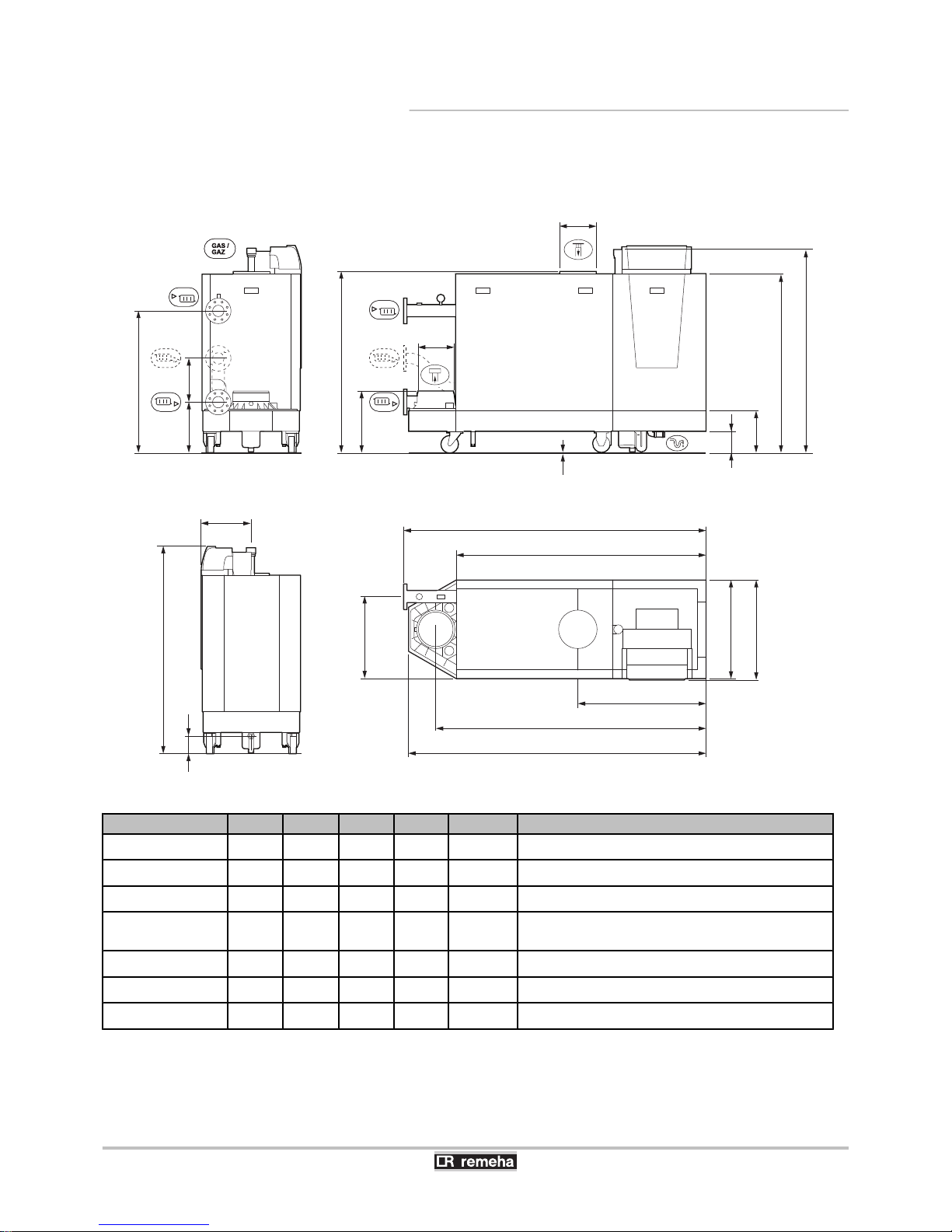
n
Boiler type Gas 310 ECO PRO
T003472-H
1500
1023
130
366
320
1477
447
1293
310
706
592
716
155
2
Ø 250
C
L
920
B
A
Ø 250
1310
353
2 2
Gas 310 ECO PRO A (mm) B (mm) C (mm) L (mm) Symbol Fittings
285 1833 1635 1862 1490
{
Heating circuit flow, Flange NW 80 (DIN 2576)
355 1833 1635 1862 1490
z
Heating circuit return, Flange NW 80 (DIN 2576)
430 1833 1635 1862 1490
Gas / Gaz
Gas connection, G2" (Female thread)
500 2142 1944 2172 1800
j
Condensates discharge, Ø 32 mm (Internal)
Condensates discharge, 1¼" (Internal)
575 2142 1944 2172 1800
i
Flue gas discharge pipe, Ø 250 mm
650 2142 1944 2172 1800
h
Air intake, Ø 250 mm
d
Second return (optional), Flange NW 65 (DIN 2576))
4. Installation Gas 310 ECO PRO - Gas 610 ECO PRO
26
160514 - 125467-05
Page 29
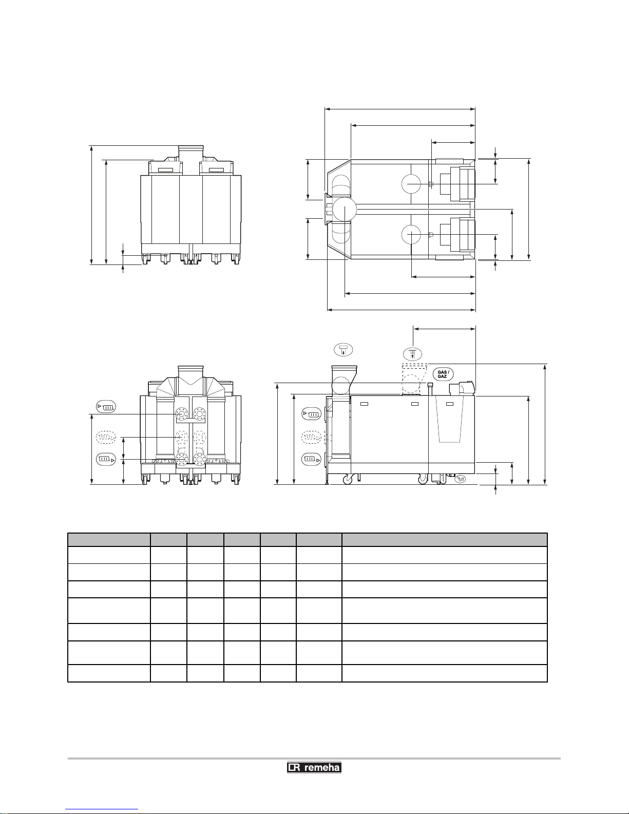
n
Boiler type Gas 610 ECO PRO
Gas 610 ECO PRO A (mm) B (mm) C (mm) L (mm) Symbol Fittings
570 1833 1582 1862 1490
{
Heating circuit flow, Flange NW 80 (DIN 2576)
710 1833 1582 1862 1490
z
Heating circuit return, Flange NW 80 (DIN 2576)
860 1833 1582 1862 1490
Gas / Gaz
Gas connection, G2" (Female thread)
1000 2142 1892 2172 1800
j
Condensates discharge, Ø 32 mm (Internal)
Condensates discharge, 1¼" (Internal)
1150 2142 1892 2172 1800
i
Flue gas discharge pipe, Ø 350 mm
1300 2142 1892 2172 1800
h
Air intake, Ø 250 mm
Air supply collector (Option), Ø 350 mm
d
Second return (optional), Flange NW 65 (DIN 2576)
T003766-J
B
920
869
A
641
L
C
592592
366 320
2 2
1023
1760
1477
1293
310
155
1500
130
1726
1310
8
8353353
722
1460
Gas 310 ECO PRO - Gas 610 ECO PRO 4. Installation
160514 - 125467-05
27
Page 30
4.4 Hydraulic connections
4.4.1. Flushing the system
The installation must be cleaned and flushed according to BS 7593
(2006).
Installing the boiler in new installations (installations less than
6 months old)
4 Clean the installation with a universal cleaner to eliminate debris
from the system (copper, hemp, flux).
4 Thoroughly flush the installation until the water runs clear and
shows no impurities.
Installing the boiler in existing installations
4 Remove sludge from the installation.
4 Flush the installation.
4 Clean the installation with a universal cleaner to eliminate debris
from the system (copper, hemp, flux).
4 Thoroughly flush the installation until the water runs clear and
shows no impurities.
Suitable chemicals and their use should be discussed with
specialist water treatment companies in respect to
aluminium heat exchangers.
4.4.2. Connection of the heating circuit
For the connection(s) of the boiler Gas 610 ECO PRO: The
features and instructions described are for each boiler
module.
CAUTION
The heating pipe must be mounted in accordance with
prevailing provisions.
1. Remove the dust cap on the central heating flow connection
Ù
.
2. Remove the dust cap on the central heating return connection
Ú
.
3.
Connect the heating water outlet pipe to the connection Ù.
4.
Connect the heating water return pipe to the connection Ú.
5. Connect a safety valve to the boiler’s flow connection.
6. Connect the pump to the boiler’s return connection.
Always connect the boiler in a way that will guarantee the water flow
through the unit during operation. When the boiler is used in a system
with two return pipes, the return pipe must be used as a lowest
temperature return. The second return pipe (accessory) is then used
as a higher temperature return. Refer to the instructions supplied with
the product. Please contact us for further information.
4. Installation
Gas 310 ECO PRO - Gas 610 ECO PRO
28
160514 - 125467-05
Page 31
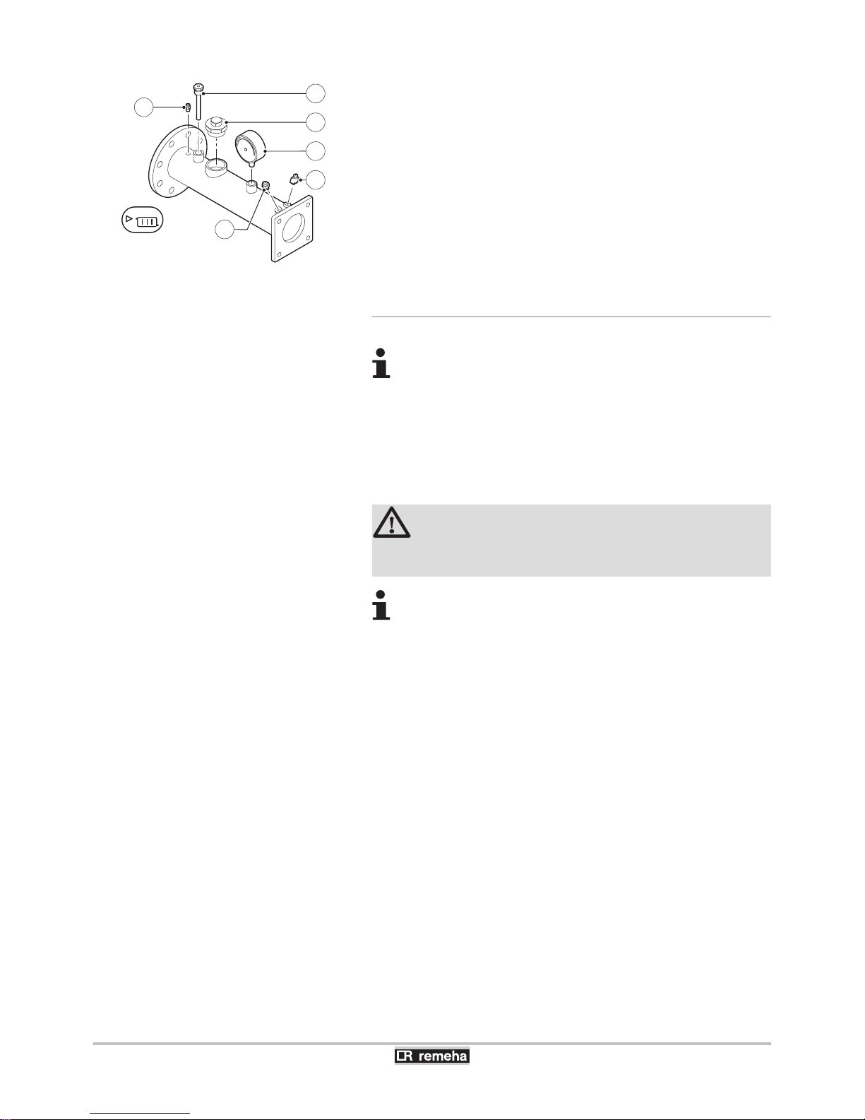
The flow pipe is fitted with the following components:
1
Tube pocket for a temperature sensor for an external
control (½").
2
Vent device (⅛").
3
Connection for safety valve (1½").
4
Pressure gauge (½").
5
Flow sensor (M6).
6
High-limit thermostat (M4).
4.4.3. Connecting the condensate discharge pipe
For the connection(s) of the boiler Gas 610 ECO PRO: The
features and instructions described are for each boiler
module.
Discharge the condensed water directly into the drain using a
syphon. In view of the acidity level (pH 2 to 5), only use plastic material
for the discharge pipe.
1. Install a plastic drain pipe on the syphon (dia. 32 mm or larger,
connected to a drain).
CAUTION
Do not make a fixed connection in order to prevent an
overpressure in the siphon.
4 The condensate drain must be connected openly to
the drain.
4 Set the discharge pipe at a gradient of at least 5 -
10 mm per metre, maximum horizontal length 5
metres.
4 Do not drain condensation water into a roof gutter at
any time.
4 Connect the condensate discharge pipe in
accordance with prevailing standards.
T003476-C
1
3
2
6
4
5
Gas 310 ECO PRO - Gas 610 ECO PRO 4. Installation
160514 - 125467-05
29
Page 32
4.5 Gas connection
For the connection(s) of the boiler Gas 610 ECO PRO: The
features and instructions described are for each boiler
module.
WARNING
4 Close the main gas valve before starting work on the
gas pipes.
4 Also fit a gas cock near the boiler.
4 Eliminate debris and dust from the gas pipes.
The boiler is fitted with a gas filter as standard.
1.
Remove the dust cap on the gas connection ß.
2. Connect the gas inlet pipe (Please refer to local rules).
4.6 Connections for the air and exhaust pipes
¼The boiler is suitable for the following types of flue gas
connections. See chapter: "Certifications", page 11.
Follow applicable local guidelines when connecting the flue gas
discharge and air supply pipes to the boiler. The diameters of the
pipes must be defined in accordance with the standards in force in
your country. The total resistance of the flue gas discharge and air
supply must not exceed the maximum acceptable resistance.
¼To determine the maximum length of the air pipes and flue gas
pipes. See chapter: "Lengths of the air/flue gas pipes", page 32.
With room sealed operation, make sure the dirt trap in the
boiler air supply remains accessible. For example, fit a T
piece with an inspection hatch in the air supply pipe directly
above the boiler.
With a flue gas connection of two or more Gas 310 ECO
PRO boilers, certain fan speeds need to be changed.
Change the values of parameters p18, p19 and
p20 for each boiler in the flue gas connection. Set them
to the values as specified in the parameter table for the
Gas 610 ECO PRO boiler.
¼See the Installation and service manual HMI GAS 310/610 ECO
PRO for comprehensive operating instructions. This includes
information about changing and reading parameters, the meaning of
fault codes and deleting the failure memory.
4. Installation
Gas 310 ECO PRO - Gas 610 ECO PRO
30
160514 - 125467-05
Page 33
4.6.1. Classification
The table specifies this classification in detail according to [.
Type Execution Description
B23
B23P
(1)
Open flue
4 Without fire-stop approval.
4 Exhaust of combustion gases above the roof.
4 Air in the installation room.
B33 Open flue
4 Without fire-stop approval.
4 Common exhaust of combustion gases above the roof.
4 Common exhaust of combustion gases mixed in the air, air in the installation room (special
construction).
C33 Room sealed flue
4 Exhaust of combustion gases above the roof.
4 The opening for the air-supply inlet is located in the same pressure zone as the vent (For
example, a concentric passage to the roof).
C53 Room sealed flue
4 Closed equipment.
4 Separate channelling for the air-supply.
4 Separate channelling for the combustion gases.
4 Air-supply inlet and flue gas outlet are located in different pressure zones.
C63 Room sealed flue
4 The manufacturer delivers this type of equipment without a supply or exhaust system.
C83
(2)
Room sealed flue
4 The equipment can be connected on a so-called semi-CLV system (with common combustion
gas exhaust).
C93
(3)
Room sealed flue
4 Channel for the air-supply and exhaust fumes in a duct or surrounded by a sleeve:
- Concentric.
- Eccentric; Air supply from the shaft.
- Exhaust of combustion gases above the roof.
- The opening for the air-supply inlet is located in the same pressure zone as the vent.
(1) Including the pressure classification P1
(2) An under pressure of 4 mbar is possible
(3) Ask your supplier for minimum dimensions of duct or sleeve
4.6.2. Outlets
The boilers can be used in room-ventilated or room-sealed
operation. The air supply connection kit must be used for closed
configurations (This is available as an accessory).
When exhausting combustion gases of type C6, the material of the
exhaust must conform with Gastec QA and/or be provided with CE
marking.
The flue gas pipes must be calculated conforming to EN 13384 (parts
1 & 2).
For open exhaust of combustion gases above the roof, the
vent must always be provided with a suitable stainless steel
wire grill.
Gas 310 ECO PRO - Gas 610 ECO PRO 4. Installation
160514 - 125467-05
31
Page 34
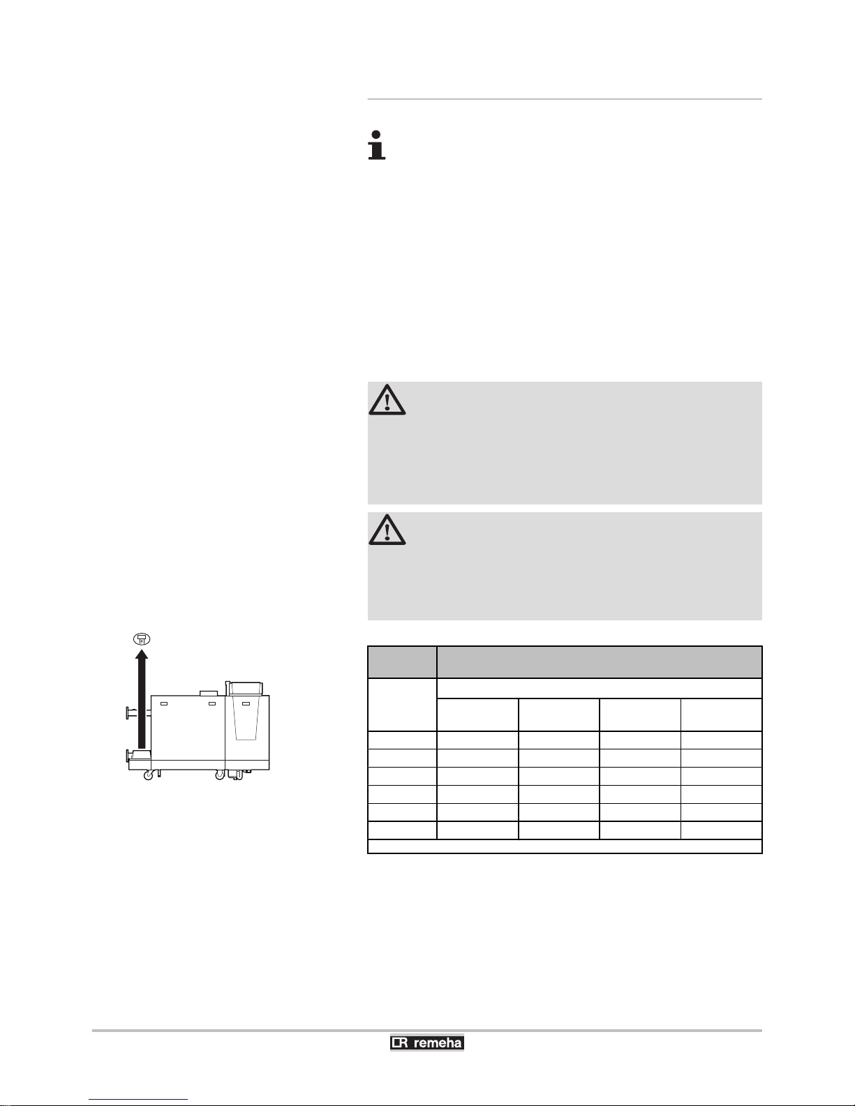
4.6.3. Lengths of the air/flue gas pipes
4 To define the maximum final length, you must deduct
the pipe length in accordance with the reduction table.
4 The boiler is also suitable for longer chimney lengths
with diameters other than those indicated in the
table. Please contact us for further information.
n
Open flue (B23, B23P)
"If using an open flue version, the air supply opening remains open;
only the combustion gas opening is connected". The boiler then takes
in the combustion air required directly from the premises in which it
is installed. For the application of air discharge and combustion gas
discharge piping with a diameter other than 250 mm, a reducer should
be used.
CAUTION
4 If the boiler, in room ventilated operation, has been
set up in a (very) dusty room, use the air supply
filter (Accessory).
4 Use of the air supply filter is compulsory when the
boiler is exposed to building dust.
CAUTION
4 The air supply opening must remain open.
4 The premises in which the appliance is installed must
be fitted with the necessary air supply openings.
They must not be reduced or closed.
Gas 310
ECO PRO
Chimney length for the open flue version
Boiler type
Maximum length (L)
(1)
with a Ø of
150 mm
with a Ø of
180 mm
with a Ø of
200 mm
with a Ø of
250 mm
285 20 m 50 m 50 m 50 m
355 11 m 30 m 50 m 50 m
430 8 m 22 m 39 m 50 m
500 7 m 18 m 32 m 50 m
575 5 m 13 m 24 m 50 m
650 5 m 12 m 21 m 50 m
(1) Calculated with rigid pipe and Outlet without hood (open ’free’)
R000363-A
L =
4. Installation Gas 310 ECO PRO - Gas 610 ECO PRO
32
160514 - 125467-05
Page 35
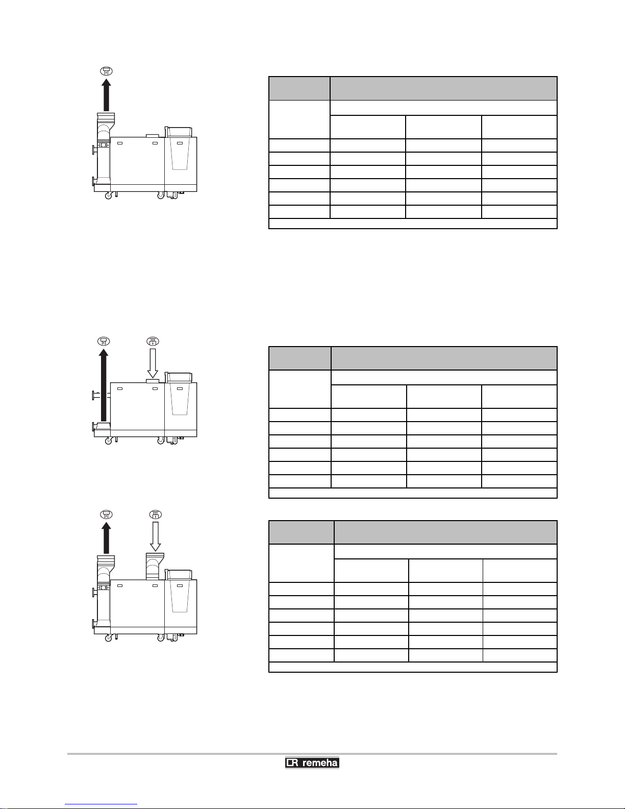
Gas 610 ECO
PRO
Chimney length for the open flue version
Boiler type
Maximum length (L)
(1)
with a Ø of 250mmwith a Ø of 300mmwith a Ø of 350
mm
570 50 m 50 m 50 m
710 31 m 50 m 50 m
860 20 m 50 m 50 m
1000 11 m 39 m 50 m
1150 5 m 26 m 50 m
1300 3 m 19 m 50 m
(1) Calculated with rigid pipe and Outlet without hood (open ’free’)
n
Room sealed flue (C33, C63, C93)
If using a room sealed version, it is necessary to connect both the
combustion gas exhaust and the air-supply opening (parallel). For the
application of air discharge and combustion gas discharge piping with
a diameter other than 250 mm, a reducer should be used.
Gas 310 ECO
PRO
Chimney length for room sealed operation
Boiler type
Maximum length (L)
(1)
with a Ø of 200mmwith a Ø of 250mmwith a Ø of 300
mm
285 42 m 50 m 50 m
355 21 m 50 m 50 m
430 13 m 50 m 50 m
500 10 m 50 m 50 m
575 5 m 34 m 50 m
650 4 m 30 m 50 m
(1) Calculated with rigid pipe and Outlet without hood (open ’free’)
Gas 610 ECO
PRO
Chimney length for room sealed operation
Boiler type
Maximum length (L)
(1)
with a Ø of 300mmwith a Ø of 350mmwith a Ø of 400
mm
570 50 m 50 m 50 m
710 43 m 50 m 50 m
860 26 m 50 m 50 m
1000 13 m 35 m 50 m
1150 5 m 16 m 24 m
1300 - 10 m 12 m
(1) Calculated with rigid pipe and Parallel roof feed-through 350 mm (Accessory)
R000361-A
L =
R000358-A
L = +
R000362-A
L = +
Gas 310 ECO PRO - Gas 610 ECO PRO 4. Installation
160514 - 125467-05
33
Page 36
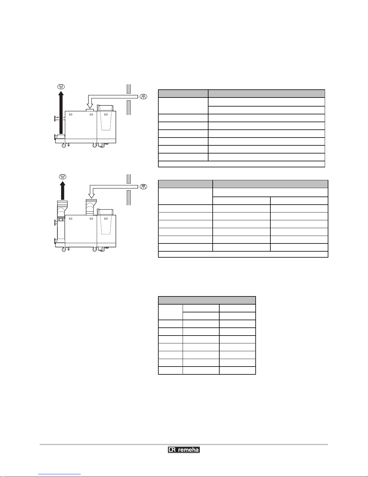
n
Connection in areas of different pressure ( C53, C83)
Combustion air supply and combustion gas discharge are possible in
various pressure zones, semi-CLV systems. The maximum
permissible difference in height between the combustion air supply
and the combustion gas discharge is 36 m.
Gas 310 ECO PRO Chimney length in the various pressure zones
Boiler type
Maximum length (L)
(1)
with a Ø of 250 mm
285 50 m
355 50 m
430 50 m
500 50 m
575 49 m
650 40 m
(1) Calculated with rigid pipe and Elbow 90º and Outlet without hood (open ’free’)
Gas 610 ECO PRO Chimney length in the various pressure zones
Boiler type
Maximum length (L)
(1)
with a Ø of 350 mm with a Ø of 400 mm
570 50 m 50 m
710 50 m 50 m
860 50 m 50 m
1000 33 m 50 m
1150 - 22 m
1300 - -
(1) Calculated with rigid pipe and Elbow 90º and Outlet without hood (open ’free’)
n
Reduction table
Pipe reductions per element used
Diameter
Elbow 45° Elbow 90°
Pipe reduction Pipe reduction
150 mm 1,2 m 2,1 m
180 mm 1,4 m 2,5 m
200 mm 1,6 m 2,8 m
250 mm 2,0 m 3,5 m
300 mm 2,4 m 4,2 m
350 mm 2,8 m 4,9 m
400 mm 3,2 m 5,6 m
R000359-A
L = +
R000360-A
L = +
4. Installation Gas 310 ECO PRO - Gas 610 ECO PRO
34
160514 - 125467-05
Page 37

4.6.4. Additional Directives
4 Please refer to the manufacturer’s instructions for the material in
question when installing the flue gas discharge and air supply
materials. If the flue gas discharge and air supply materials are not
installed according to the instructions (e.g. they are not leakproof,
not clamped in place etc.), this may cause hazardous situations
and/or result in bodily injury. After assembly, check at least all flue
gas and air–carrying parts for tightness.
4 Connection of the combustion gas exhaust directly to the buildings
brick chimneys or flues is forbidden for condensation reasons.
4 Always clean the ducts thoroughly in cases where lining pipes are
used and/or a connection of the air-supply.
4 It must be possible to inspect the flue or chimney.
4 In cases where condensate coming from the stainless steel or
plastic sections of the flue gas pipe can be driven back towards
the aluminium section, this condensate must be removed using a
collecting device before the aluminium section is reached.
4 For long, aluminium, combustion-gas exhaust pipes it is initially
necessary to consider the relatively high quantity of corrosive
products which are brought together with the condensate from the
exhaust pipe. The siphon on the equipment requires regular
cleaning or, preferably, an additional condensate collector can be
installed above the equipment.
4 The combusted gas discharge pipe must be sufficiently inclined
towards the boiler (at least 50 mm per metre) and an adequate
condensate collection tank and discharge system constructed (at
least 1 m before the boiler opening). The elbows fitted must be at
more than 90° to guarantee the provision of an adequate gradient
and tightness on the lip rings.
Please contact us for further information.
4.6.5. Connection of the combustion gas exhaust
pipe
The boiler is equipped with a mechanical flue gas non-return valve as
standard. This prevents flue gas travelling back up into the boiler
when it is not in operation. (E.g. for cascade systems).
Mounting
1. Fit the combustion product discharge conduit.
Gas 310 ECO PRO - Gas 610 ECO PRO
4. Installation
160514 - 125467-05
35
Page 38
2. Fit together the combustion gas exhaust pipes, without welding.
4 The pipes must allow no leakage of flue gases and be
resistant to corrosion.
4 Connect the pipes together without stress between
the sections.
4 Maximum bracket distance from vertical pipes is 2 m.
4 Maximum tilt of vertical pipes is 20 mm/m.
4 The pipes must not rest on the boiler or flue gas
adapter.
4 The horizontal sections need to be constructed with a
gradient of 50 mm per metre: Back to the boiler.
4 Use a bracket at each connection from horizontal
pipes.
4.6.6. Connection of the air intake pipe
Mounting
1. Fit the air-intake conduit.
2. Fit the air-intake conduits together without welding.
4
The pipes must be airtight and corrosion-resistant.
4 Connect the pipes together without stress between
the sections.
4 Maximum bracket distance from vertical pipes is 2 m.
4 Maximum tilt of vertical pipes is 20 mm/m.
4 The pipes must not rest on the boiler or air supply
adapter.
4 The horizontal sections need to be constructed with a
gradient: Downwards in the direction of the supply
opening.
4 Use a bracket at each connection from horizontal
pipes.
Material
Single wall, rigid
aluminium/Stainless steel
(1)
Flexible
(1) The materials used must comply with the prevailing regulations and standards
4.7 Electrical connections
For the connection(s) of the boiler Gas 610 ECO PRO: The
features and instructions described are for each boiler
module.
4. Installation Gas 310 ECO PRO - Gas 610 ECO PRO
36
160514 - 125467-05
Page 39
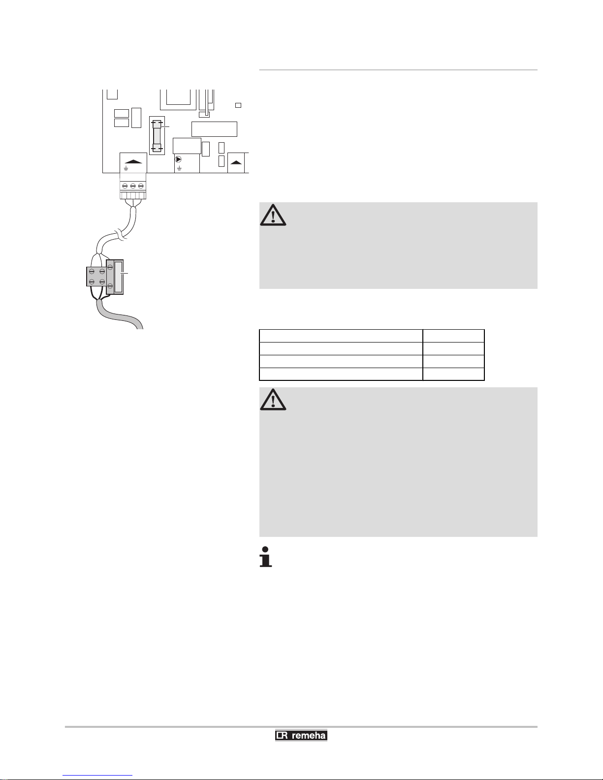
4.7.1. Control unit
PW
Pre-wired in the boiler
M
Three wired power cord
The boiler has a detection phase. The boiler is fully pre-wired. The
boiler is suitable for a 230 V / 50 Hz power supply with live/neutral/
earth. Other connection values are only acceptable if an isolating
transformer is installed. Connect the wires of the mains lead to the
appropriate terminal block. This can be found to the left underneath
the connector MAINS. (The mains lead is not supplied).
CAUTION
4 In the case of a fixed connection to the power cord,
you must always install a main bipolar switch with an
opening gap of at least 3 mm.
4 When connecting the mains lead to the plug, the
earth wire must be longer than the electrical wires.
The main characteristics of the control unit are described in the table
below.
Power supply voltage 230 VAC/50Hz
Rating of the main fuse F2 (230 VAC) 10 AT
Fuse rating F1 (230 VAC) 2 AT
Maximum power consumption of the pump 300 VA
WARNING
The following boiler components are at a voltage of
230V:
4 Electrical connection of the heating pump (Central
heating) (if used).
4 Electrical connection of the combined gas valve unit.
4 Fan.
4 The majority of components in the control panel.
4 Ignition transformer.
4 Connection of the power supply cable.
The boiler has a unique boiler code. This, together with
other data, incl. boiler type, counter readings, etc. is stored
in a (PSU) that belongs with the boiler. If the control unit is
replaced, the counter readings remain stored in it.
It is possible to connect various control, safety and regulation systems
to the boiler. The heat output of the boiler can be controlled as follows:
4 Adjustable control: The output varies between the minimum and
maximum value on the basis of the value determined by the
controller.
4 Analogue setting: Where the heat output or the temperature is
controlled by a 0-10V signal.
N L
Mains
F1
N L
PUMP
ON/OFF
OT BL
F2
PW
M
T003486-E
Gas 310 ECO PRO - Gas 610 ECO PRO
4. Installation
160514 - 125467-05
37
Page 40
4 On/Off setting: where the heat output modulates between the
minimum and maximum value based on the flow temperature set
in the boiler.
¼The standard control PCB (PCU-06) can be extended with the
following, for example: "Accessories", page 19
4.7.2. Recommendations
WARNING
4 Only qualified professionals may carry out electrical
connections, always with the power off.
4 The boiler is entirely pre-wired. Do not modify the
connections inside the control panel.
4 Earth the appliance before making any electrical
connections.
Make the electrical connections of the boiler according to:
4 The instructions of the prevailing standards.
4 The instructions on the electrical diagrams provided with the
boiler.
4 The recommendations in the instructions.
CAUTION
Separate the sensor cables from the 230 V cables.
4.7.3. Standard control PCB
The protection PCB SU, which protects the boiler, is connected to the
standard control PCB PCU-06.
Various thermostats and controllers can be connected to the standard
control PCB (PCU-06). The possible connections on the standard
control PCB are described in the following paragraphs.
4. Installation Gas 310 ECO PRO - Gas 610 ECO PRO
38
160514 - 125467-05
Page 41
A clearance of 20 cm is required above the instrument
panel to allow the front cover to open fully. Bear this in mind
when installing cable ducts.
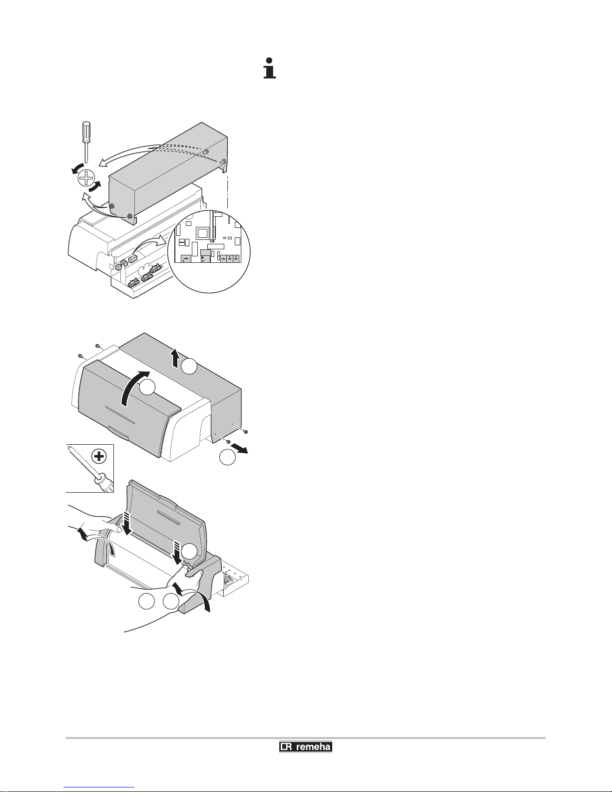
Access to the connector block:
1. Unscrew the 4 lateral holding screws in the control panel.
2. Remove the protective cover.
3. The detachable screw connectors are now accessible.
4. Secure cable(s) using the traction clip and the cable clamps (The
cable clamps are supplied separately).
5. Firmly retighten the cable clamps and close the control panel.
Accessing the PCBs behind the control panel:
1. Unscrew the 4 lateral holding screws in the control panel.
2. Remove the protective cover.
3. Open the front cover.
4. Use both thumbs to press the top of the control panel downwards
a little.
5. While maintaining some of the pressure you are applying to the
top of the control panel, use both hands to tip the casing forwards
and upwards.
T003477-D
N L
Mains
N L
PUMP
ON/OFF
OT RLBL
T004637-B
54 +
4
14x
2
3
Gas 310 ECO PRO - Gas 610 ECO PRO 4. Installation
160514 - 125467-05
39
Page 42
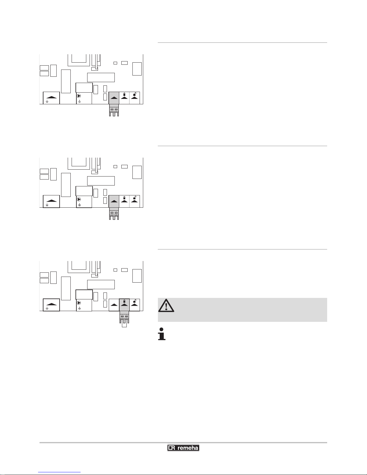
4.7.4. Connecting the on/off control
The boiler can be controlled with an on/off controller. Connect the
controller to the ON/OFF-OT connector. (It does not matter which wire
is connected to which cable clamp).
4.7.5. Connecting modulating controller
The boiler is fitted with a OpenTherm connection as standard. As a
result, modulating OpenTherm room controllers can be connected
without any further adjustments. Connect the two-wire cable to
terminals ON/OFF-OT of the connector (It does not matter which wire
is connected to which cable clamp).
4.7.6. Shutdown input
The boiler has a shutdown input (Normally closed contact). If this
contact is opened, the boiler will go into shutdown or be locked out.
This input can be used for example in combination with the flue gas
thermostat (Accessory). This input is on the BL terminals of the
connector.
CAUTION
Only suitable for potential-free contacts.
Remove the bridge before using the input
The behaviour of the input can be changed using parameter
p35.
N L
Mains
N L
PUMP
ON/OFF
OT RLBL
T003482-A
N L
Mains
N L
PUMP
ON/OFF
OT RLBL
T003482-A
N L
Mains
N L
PUMP
ON/OFF
OT RLBL
T003483-B
4. Installation
Gas 310 ECO PRO - Gas 610 ECO PRO
40
160514 - 125467-05
Page 43
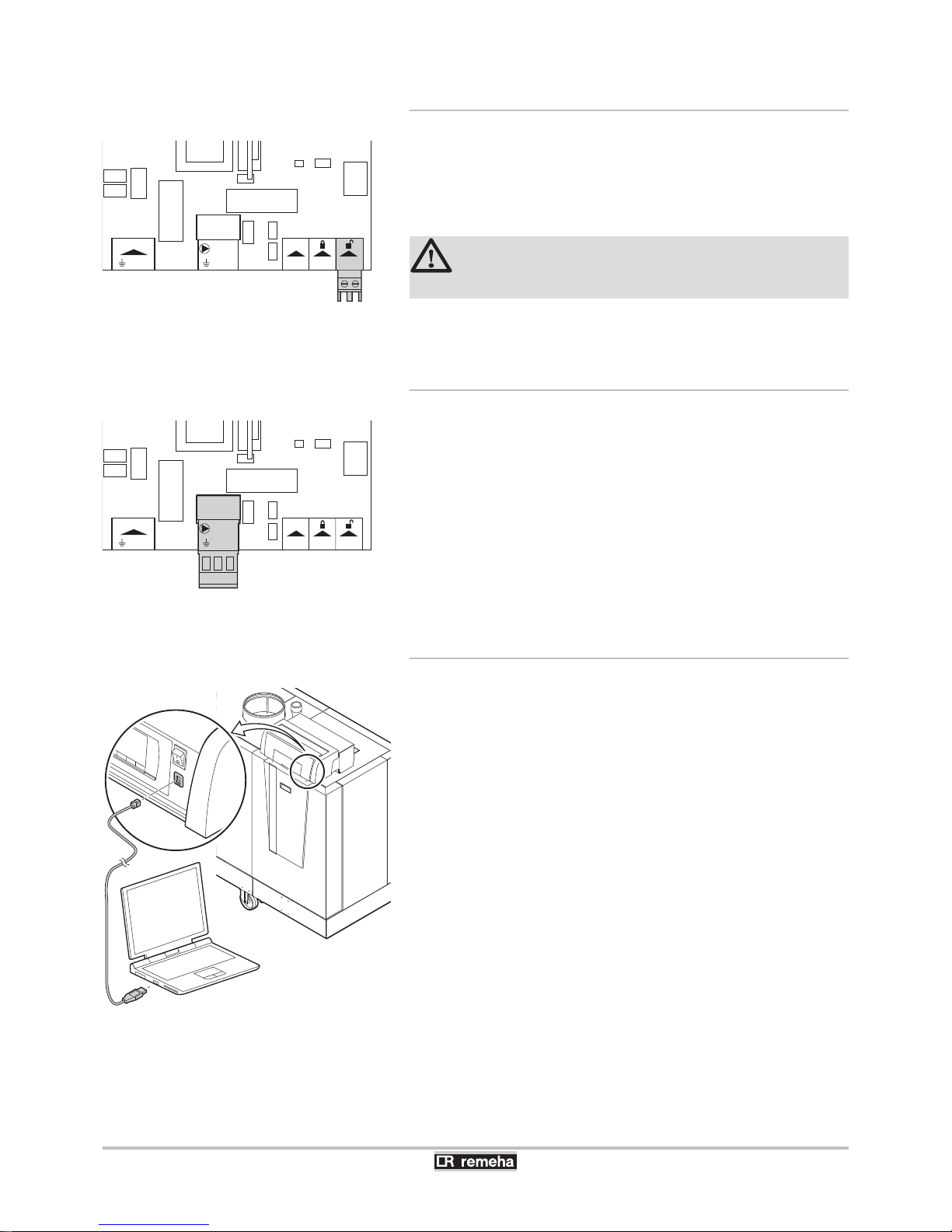
4.7.7. Release input
The boiler has a release input (Normally open contact). If this contact
is closed when there is a heat demand, the burner will go into
shutdown after a waiting time. This input can be used in combination
with the limit switches on flue gas dampers, hydraulic shutter valves,
etc.. This input is on the RL terminals of the connector.
CAUTION
Only suitable for potential-free contacts.
The waiting time of the input can be changed using parameter
p32.
4.7.8. System pump
An external central heating pump can be connected to the Pump
terminals of the connector. The maximum input power is 300 VA.
¼For more information on controlling a modulating pump See
paragraph: "Connection possibilities for the PCB (SCU-S05)", page
42
4.7.9. PC/Laptop connection
A PC can be connected to the RS 232 input using an USB cable.
Using the Recom PC/Laptop service software, you can enter, change
and read out various boiler settings.
N L
Mains
N L
PUMP
ON/OFF
OT RLBL
T003484-B
N L
Mains
N L
PUMP
ON/OFF
OT RLBL
T003485-B
T003492-E
Gas 310 ECO PRO - Gas 610 ECO PRO 4. Installation
160514 - 125467-05
41
Page 44
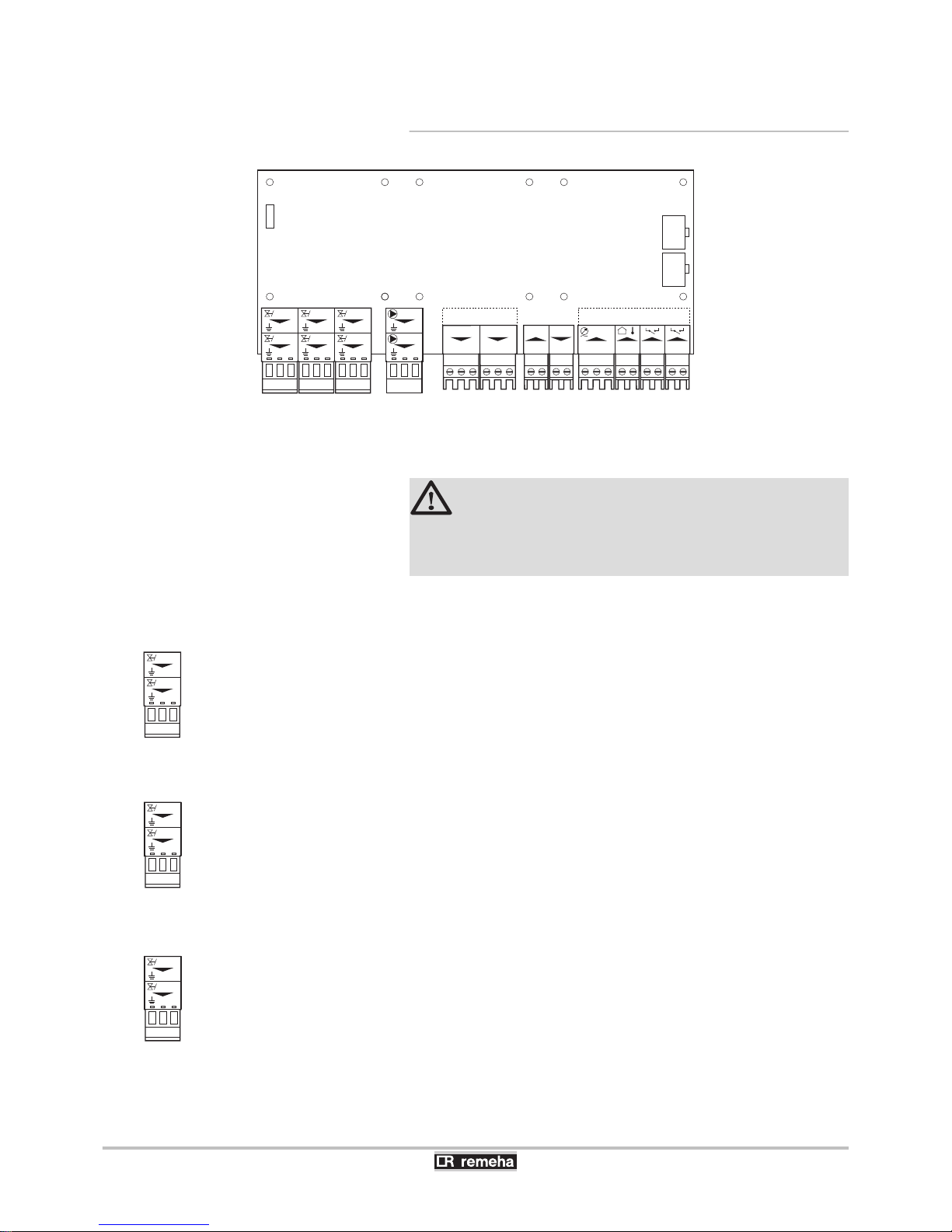
4.7.10. Connection possibilities for the PCB (SCU-
S05)
T003684-C
X2
SCU-S05
X1
X3
X7X6X4 X5
N L
N
L
EgV
N L
EgV
N L
HdV
N L
HdV
N L
FgV
FgV
X9
X8
+0 S
+0
Wps
S
Gps
Gps
VPS
VPS+0
+0
+0
+0
Ctrl0-10
Pump
N L
N
Pump
L
NoNc C
NoNc C
Status
NoNc C
NoNc C
Status
Tout
Tout
¼To set the parameter selected: See the Installation and service
manual HMI Gas 310/610 ECO PRO for comprehensive operating
instructions.
CAUTION
On removing this PCB, the boiler will show fault code
e[38. To prevent this fault, an auto-detect must be
carried out after removing this PCB.
n
Flue gas damper control (FgV)
Not applicable.
n
Hydraulic valve control (HdV)
In a cascade configuration, a hydraulic valve prevents heat loss when
the boiler is not running. Connect the hydraulic valve to the HdV
terminals of the terminal strip. The running time of the hydraulic valve
must be programmed with parameter p30.
n
Control of external gas valve (EgV)
If there is a heat demand, an alternating voltage of 230 VAC, 1 A
(maximum) becomes available on the EgV terminals of the connector
to control an external gas valve.
R000303-A
N L
N L
FgV
FgV
R000304-A
HdV
N L
HdV
N L
R000305-A
EgV
N L
EgV
N L
4. Installation
Gas 310 ECO PRO - Gas 610 ECO PRO
42
160514 - 125467-05
Page 45
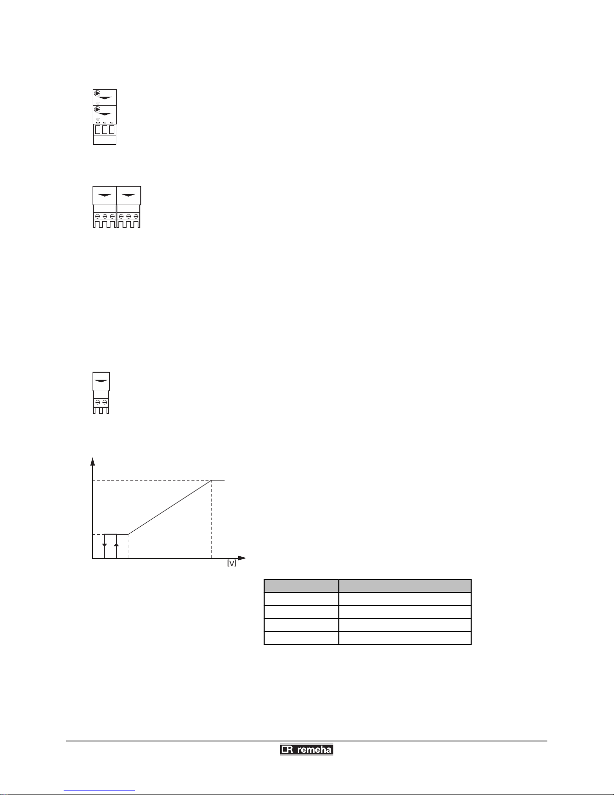
n
Connecting a shunt pump (Pump)
If required, a shunt pump may also be installed on the terminals
Pump of the connector. Only an on/off pump can be controlled. The
pump is activated during lock outs 5t:9 (5v:4,5 and 6). The
maximum input power is 300 VA.
n
Operation signal and failure signal (Status)
The alarm or operation signal is selected using parameter p26
(Connector X4).
The alarm or operation signal is selected using parameter p27
(Connector X5).
4 If the boiler is operating, the operation signal can be switched via
a potential-free contact (maximum 230 VAC, 1 A) on the No and
C terminals of the connector.
4 If the boiler locks out, the alarm can be transmitted via a potential-
free contact (maximum 230 VAC, 1 A) on the Nc and C terminals
of the connector.
n
Analogue output (Ctrl)
The function of the analogue output can be set using parameter
p36.
An outgoing 0-10 V signal can be used either to report the supplied
heat output or the supplied temperature.
The speed of the system pump can be controlled with an outgoing
0-10 V signal. (Only possible if the pump is suitable for this).
Control of 0-10V Wilo system pump
R
Pump regime
min
Minimum pump speed
max
Maximum pump speed
Off
The pump is off
U
Output signal (V)
Output signal (V) Description
<1 Pump off
1 - 2 Hysteresis
2 - 3 Pump on (Minimum pump speed)
3 - 10 Pump modulates (Linear)
R000306-A
Pump
N L
N
Pump
L
R000307-B
NoNc C
NoNc C
Status
NoNc C
NoNc C
Status
R000308-B
+0
+0
Ctrl
max
min
Off
1 2 3
4 5 6 7 8 9 10
T003802-B
U
R
Gas 310 ECO PRO - Gas 610 ECO PRO 4. Installation
160514 - 125467-05
43
Page 46
Control of 0 - 10 V Grundfos system pump
R
Pump regime
min
Minimum pump speed
max
Maximum pump speed
Sp
Nominal set-point
U
Output signal (V)
Output signal (V) Description
<0,5 Pump on (Minimum pump speed)
>0,5 Pump modulates (Linear)
Control of PWM system pump
In this case, the 0-10 V signal controls the system pump linear.
Message about the supplied temperature
Output signal (V)
Temperature °C Description
0,5 - Lock out
1 - 10 10 - 100 Delivered temperature
Message about the supplied heat output
Output signal (V)
Heat output (%) Description
0 0 Boiler off
0,5 - Lock out
2,0 - 10
(1)
20 - 100 Heat output supplied
(1) Dependent on the minimum modulation depth (set speeds, standard 20%)
n
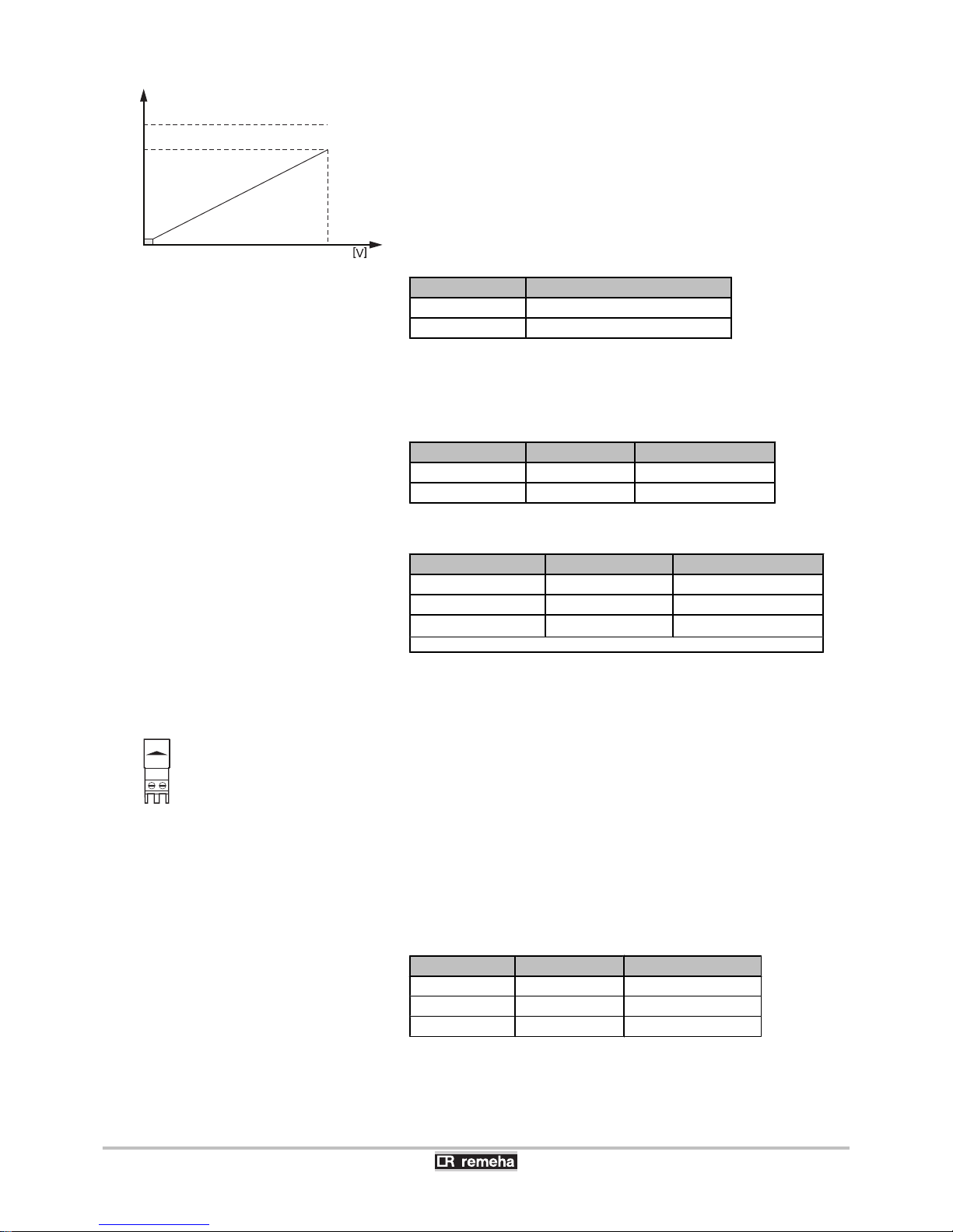
Analogue input (0-10 V)
The function of the analogue input can be set using parameter
p37.
This control can be based on temperature or heat output. If this input
is used for 0-10 V control, then the boiler OT communication is
ignored.
Analogue temperature-based control (°C)
The 0 - 10 V signal controls the boiler flow temperature. This control
modulates on the basis of flow temperature, whereby the heat output
varies between the minimum and maximum values on the basis of
the flow temperature set point calculated by the controller.
Input signal (V)
Temperature °C Description
0 - 1,5 0 - 15 Boiler off
1,5 - 1,8 15 - 18 Hysteresis
1,8 - 10 18 - 100 Temperature required
Analogue heat output-based control (%)
max
Sp
min
R
1 2 3
4 5 6 7 8 9 10
T003803-B
U
R000309-A
+0
+0
0-10
4. Installation
Gas 310 ECO PRO - Gas 610 ECO PRO
44
160514 - 125467-05
Page 47
The 0 - 10 V signal controls the boiler output. The minimum and
maximum values are limited. The minimum output is linked to the
boiler’s modulation depth. The output varies between the minimum
and maximum value on the basis of the value determined by the
controller.
Input signal (V) Heat output (%) Description
0 - 2,0
(1)
0 - 20 Boiler off
2,0 - 2,2
(1)
20 - 22 Hysteresis
2,0 - 10
(1)
20 - 100 Heat output requested
(1) Dependent on the minimum modulation depth (set speeds, standard 20%)
n
Hydraulic pressure sensor (Wps)
The hydraulic pressure sensor registers the water pressure and can
shut the boiler down when the minimum water pressure is reached.
To activate this blocking option, a minimum pressure must be set with
parameter p"8. Connect the hydraulic pressure sensor to the
Wps terminals of the terminal strip.
0 = Earth or neutral of the power supply
S = Signal or output from the sensor
+ = Supply voltage
n
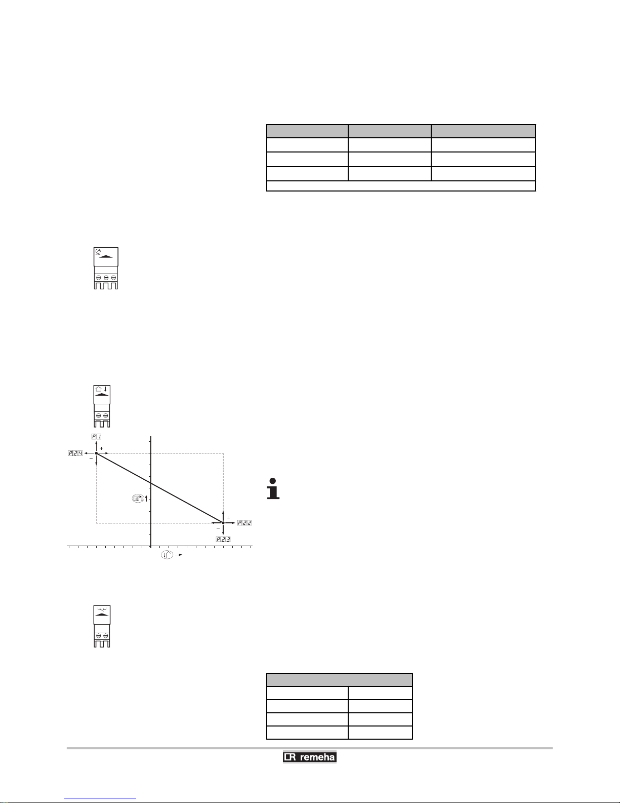
Connecting the (Tout) outside temperature sensor
An outside sensor can be connected to the Tout terminals of the
connector (Accessory). Where there is an on/off thermostat controller,
the boiler will control the temperature with the set point of the internal
heating curve.
If an outside temperature sensor is connected, it is possible to adapt
the heating curve. The setting can be modified using parameters
p1, p"2, p"3 and p"4.
A OpenTherm controller can also use this outside
sensor. The heating curve required must then be set on the
controller.
n
Pressure switch minimum (Gps)
The minimum gas pressure switch shuts the boiler down if the inlet
gas pressure becomes too low. Check the setting of the minimum gas
pressure switch Gps. (See table below). Connect the minimum gas
pressure switch to the Gps terminals of the connector. The presence
of the gas pressure switch must be set using parameter p29.
Pressure switch minimum
Gas 310 ECO PRO
Minimum value
285 14 mbar
355 13 mbar
430 10 mbar
R000310-A
+0 S
+0
Wps
S
R000311-A
Tout
Tout
T003800-A
0 10 20
-20
-10
10
30
70
50
90
F
R000312-A
Gps
Gps
Gas 310 ECO PRO - Gas 610 ECO PRO 4. Installation
160514 - 125467-05
45
Page 48
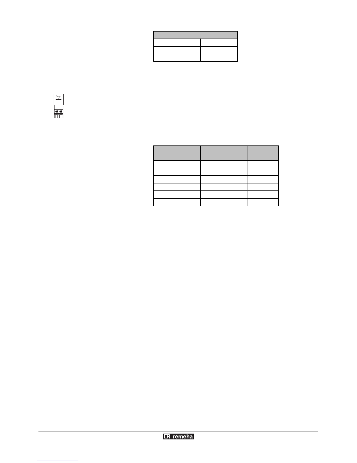
Pressure switch minimum
500 10 mbar
575 10 mbar
650 10 mbar
n
Gas valve leak proving system (Vps)
The gas leakage control checks and controls the safety valves on the
gas block. The test takes place before the boiler starts up. In the event
of a leak in the gas block, the boiler will lock out. The pressure switch
must be set at 50 % of the admission pressure (See table below).
Connect the gas leakage control to the Vps terminals of the terminal
strip. The presence of the gas leak control must be specified using
parameter p33 in the setting mode.
Boiler type
Gas 310 ECO PRO
Gas inlet pressure
(Max)
VPS setting
(Max)
285 30 15
355 30 15
430 100 40
500 100 40
575 100 40
650 30 15
R000313-A
VPS
VPS
4. Installation Gas 310 ECO PRO - Gas 610 ECO PRO
46
160514 - 125467-05
Page 49
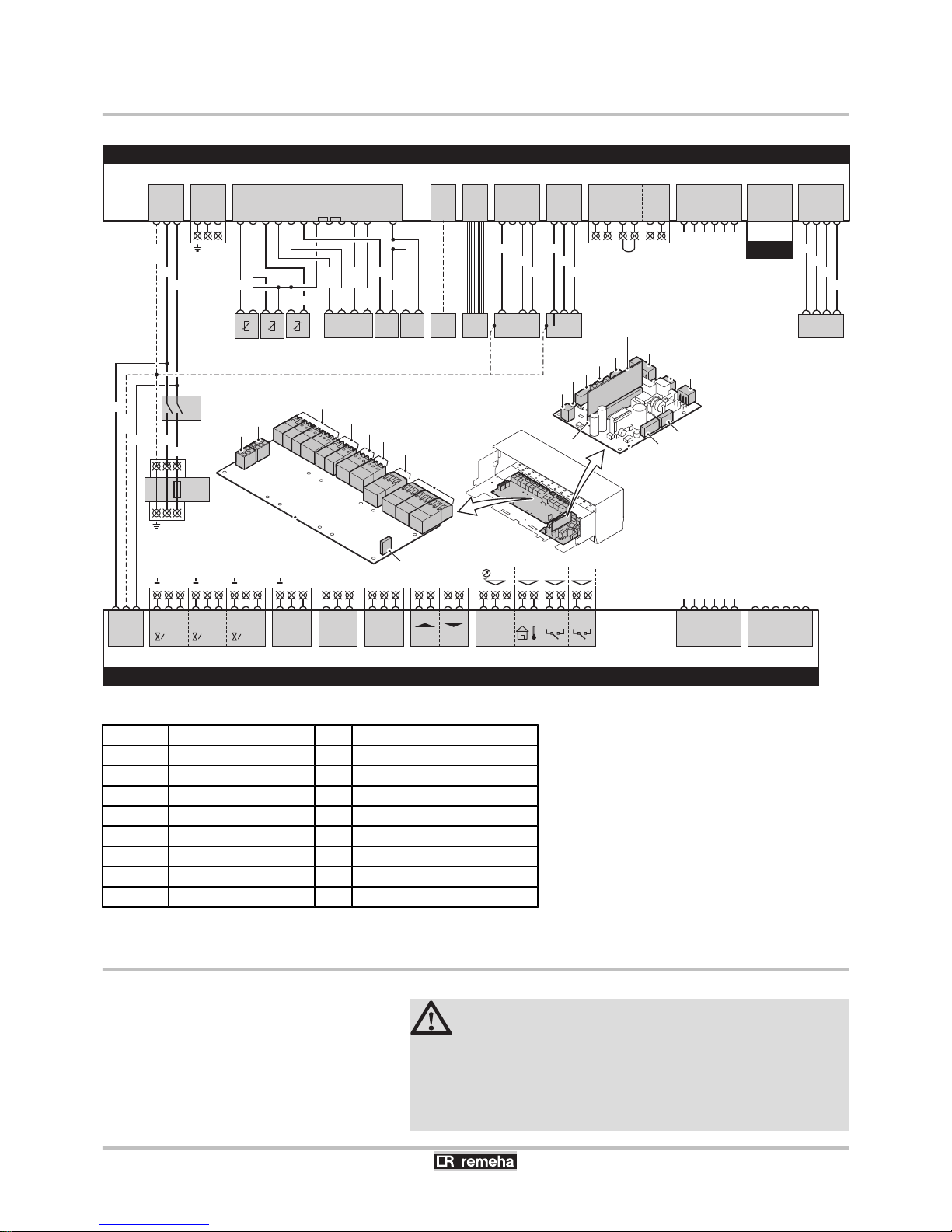
4.8 Electrical diagram
SCU-S05
Extended control PCB
RTs
Return sensor
PCU-06
Standard control PCB
PSU
Storage parameter
SU-01
Safety PCB
HLs
Safety thermostat
AU
On/Off switch
PS
Air differential pressure switch
P
Power supply
PC
Connecting a computer
N
Neutral
HMI
Control panel
L
Phase
GB
Gas block
Fs
Flow switch
IT
Ignition transformer
HEs
Heat exchanger sensor
FAN
Fan
4.9 Filling the system
CAUTION
Great care is required during water treatment. For more
information, refer to our publication water quality rules.
The rules in the aforementioned document must be
respected. This manual forms a part of the documentation
supplied with the boiler.
R000236-C
SCU-S05
PCU-06
X06
1 2 3 4
N LL
GB
BL
BR
BR
X07
1 2 3
ION
LN
IT
GY
BL
BK
X02
1 2
Pump
3
LN
Fgv
21
Hdv
4 5
Egv
7 83 6 9
N N NL L L
X02
P
X50
10 AT
LN
X08
1 2 3 4 5 6
X09
1 2 3 4 5 6
PUMP
21 3
N L
X03
Status
C NoNc
21 3
X04
Status
C NoNc
21 3
X05
0-10V 0-10V
-+ + -
X06
O S +
21 4 5
6 73 8 9
X07
Wps Tout Gps VPs
X04PCX05
1 10
HMI
X11
1 2 3 4
1 4 25
FAN
WH
BR
GN
YW
X09
1 2 3 4 5 6
OT
1
On / Off
bL
3 4
RL
5 62
X08
AU
X51
X01
1 2 3
X01
1 2 3
Mains
YW/
GN
BL
BK
BL
BR
BL
BK
YW/
GN
SCU-05
X01
X07
X08
X09
X06
X05
X04
X03
X02
PCU-06
X06
X07
X08
X02
X03
X11
X09
X04
X10
X05
X01
SU-01
X03
1 92 3 4 5 10 116 7 8 12
Fs
HEs
PSU
WH BL
RD
BK
HLs
OR
OR
PS
YW/
WH
BR/
WH
BK/
WH
BL/
WH
RTs
SU-01
X10
Gas 310 ECO PRO - Gas 610 ECO PRO 4. Installation
160514 - 125467-05
47
Page 50
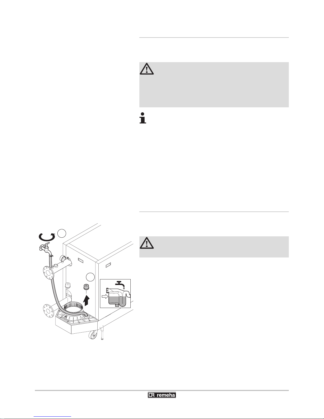
4.9.1. Water treatment
In most cases, the boiler and the central heating installation can be
filled with normal tap water and no water treatment will be necessary.
WARNING
Do not add chemical products to the central heating water
without consulting Remeha. For example: antifreeze,
water softeners, products to increase or reduce the pH
value, chemical additives and/or inhibitors. These may
cause faults in the boiler and damage the heat exchanger.
4 Rinse the central heating installation with at least 3x
the volume of the central heating installation. Flush
the DHW pipes with at least 20 times the volume of
the pipes.
4 For untreated water, the pH value of the water in the
installation must be between 7 and 9 and for treated
water between 7 and 8.5.
4 The maximum hardness of the water in the installation
must be between 0.5 - 20.0 °dH (Depending on the
total installed heat output).
4 For more information, refer to our publication water
quality rules. The rules in the aforementioned
document must be respected.
4.9.2. Filling the siphon
1. Fill the siphon with water via the condensate tank (Up the level
marker).
CAUTION
Reinsert the condensate collector sealant cap.
T003489-D
1
2
4. Installation Gas 310 ECO PRO - Gas 610 ECO PRO
48
160514 - 125467-05
Page 51
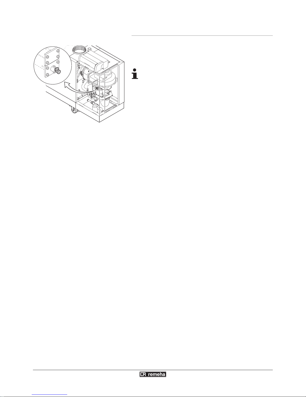
4.9.3. Filling the system
1. Fill the system with clean tap water. The boilers can function at an
operating pressure of between 0.8 - 7 bar.
2. Check the tightness of the water connections.
4 If the water pressure is lower than 0.8 bar, the symbol
e will appear. Only with the hydraulic pressure
sensor connected (Accessory). If necessary, top up
the water level in the heating system.
4 A filling and drain cock is fitted on the front section as
standard (½").
T003772-F
Gas 310 ECO PRO - Gas 610 ECO PRO 4. Installation
160514 - 125467-05
49
Page 52
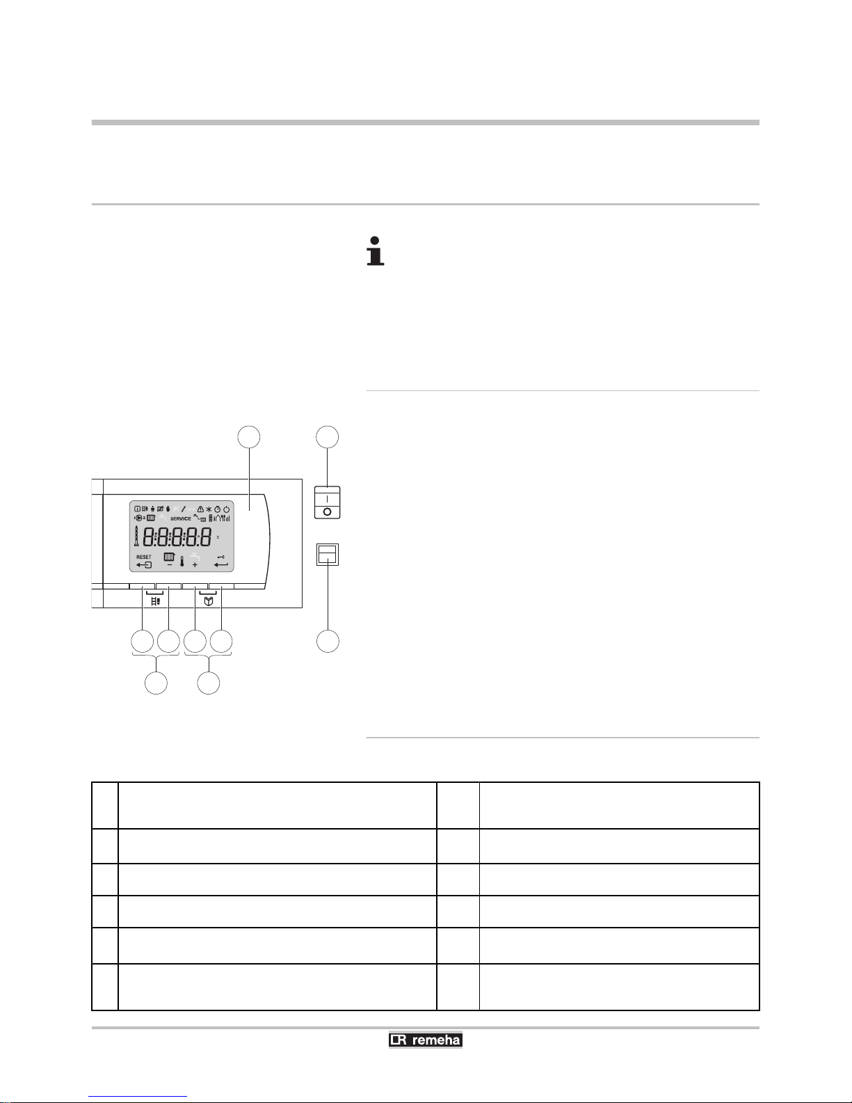
5 Commissioning
5.1 Control panel
For operation of the boiler Gas 610 ECO PRO: Each
module has its own instrument panel.
¼See the Installation and service manual HMI GAS 310/610 ECO
PRO for comprehensive operating instructions. This includes
information about changing and reading parameters, the meaning of
fault codes and deleting the failure memory.
5.1.1. Functions of the keys
1
Display
2
> [Escape] or J key
3
D Heating temperature key or [-]
4
[+] key
5
S [Enter] or cancel d Key lock-out
6
B [Chimney-sweeping] keys
(press the 2 and 3 keys simultaneously)
7
f [Menu] keys
(press the 4 and 5 keys simultaneously)
8
On/Off switch
9
PC connection
5.1.2. Meaning of the symbols on the display
Q
Information menu:
Reading the various current values.
/
On/Off switch (0/1):
After 5 lock-outs, the boiler must be switched off/on
again.
B
Chimney-sweeping position:
Forced full or part load for CO2 measurement.
b
Circulation pump:
The pump operates.
W
User menu:
Parameters at user level can be changed.
D
Central heating function:
Access to central heating temperature parameter.
C
Heating programme deactivated:
The heating function is deactivated.
d
Locking the keys:
Key lock-out is activated.
E
Manual mode:
Boiler is set to manual operation.
K
Yellow display with the symbols:
$ + K + Z (Maintenance message).
?
Service menu:
Parameters at installer level can be changed.
e
Water pressure:
The water pressure is too low. Only with the hydraulic
pressure sensor connected (Accessory).
T003479-D
rpm
kWµA
± 30l/min
barPsi
St ºC
ºCºFh
2
1 8
3 4 5 9
6 7
5. Commissioning Gas 310 ECO PRO - Gas 610 ECO PRO
50
160514 - 125467-05
Page 53
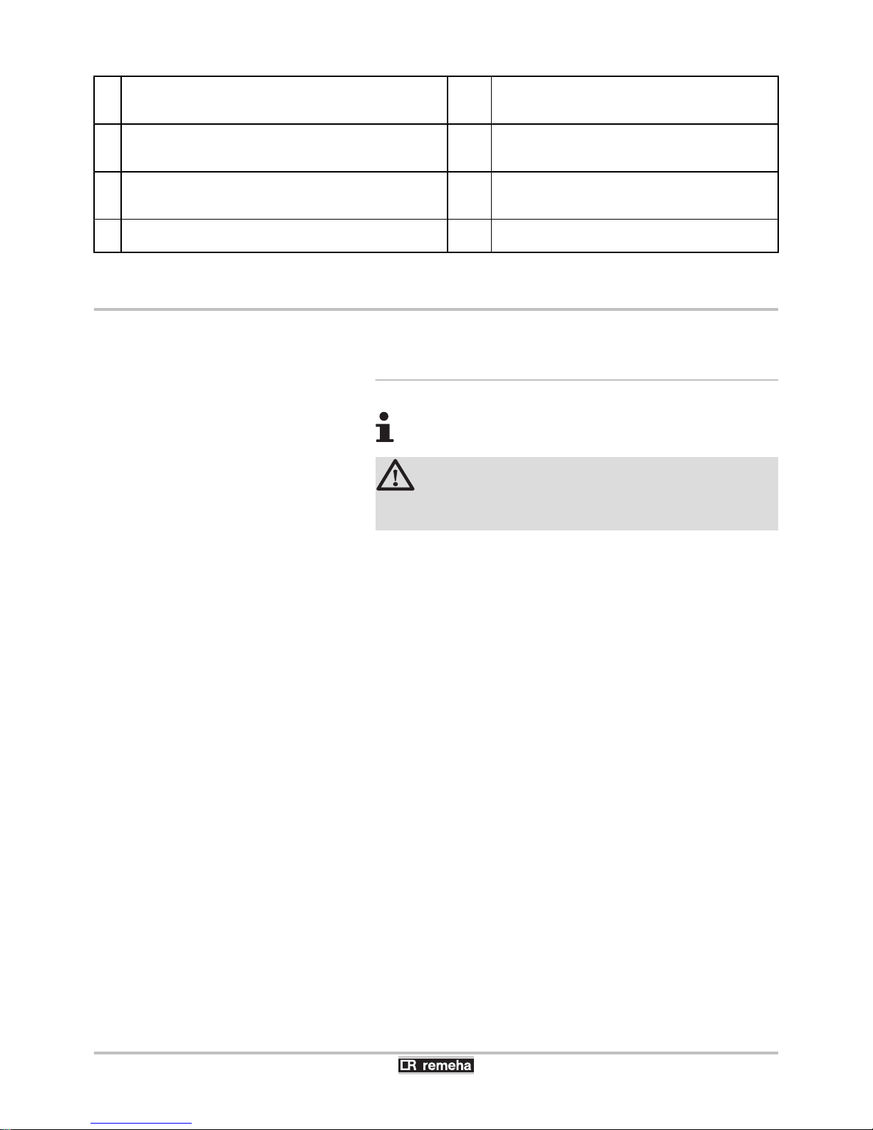
c
Defect:
Boiler indicates a fault. This can be seen from the e code
and red display.
]
Antifreeze protection:
Boiler is running in frost protection mode.
\
Hour counter menu:
Readout of the operating hours, number of successful starts
and hours on mains supply.
I
Burner level:
Output level .
Z
Outside sensor:
Only if an outside temperature sensor is connected
(Accessory).
[
Signal strength symbol:
Signal strength of the wireless controller (If
connected)..
g
Battery symbol:
Status of battery of wireless controller (If connected).
5.2 Check points before commissioning
5.2.1. Preparing the boiler for commissioning
For work on the boiler Gas 610 ECO PRO: The features
and instructions described are for each boiler module.
WARNING
Do not put the boiler into operation if the supplied gas is
not in accordance with the approved gas types.
Preparatory procedure for boiler commissioning:
4 Check that the gas type supplied matches the data shown on the
boiler’s data plate.
4 Check the gas circuit.
4 Check the hydraulic circuit.
4 Check the water pressure in the heating system.
4 Check the tightness of the flue gases evacuation and air inlet
connections.
4 Check the electrical connections to the thermostat and the other
external controls.
4 Check the other connections.
4 Test the boiler at full load. Check the setting of the gas/air ratio
and, if necessary, correct it.
4 Test the boiler at part load. Check the setting of the gas/air ratio
and, if necessary, correct it.
4 Finalizing work.
4 Complete the checklist.
¼See chapter: "Checklist for commissioning", page 77.
Gas 310 ECO PRO - Gas 610 ECO PRO
5. Commissioning
160514 - 125467-05
51
Page 54
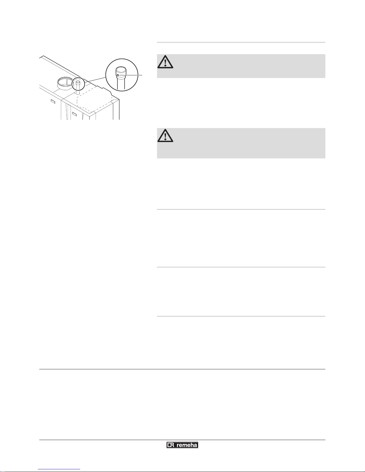
5.2.2. Gas circuit
WARNING
Ensure that the boiler is switched off.
1. Open the main gas supply.
2. Remove the casings on the inspection side.
3. Measure the inlet gas pressure via the measuring point C on the
gas pipe.
The pressure must be the same as the one shown on the rating
plate.
WARNING
¼
To ascertain the gas types permitted, see chapter:
"Equipment categories", page 12.
4. Check the tightness of the gas line, including the gas valves.
5. Purge the gas supply pipe by unscrewing the screw from the gas
pression socket C. Tighten the measurement point when the pipe
has been sufficiently purged.
5.2.3. Hydraulic circuit
4 Check the syphon — this must be completely filled with clean
water (Up the level marker).
4 Check the tightness of the water connections.
5.2.4. Connections for the air and exhaust pipes
4 Check the tightness of the flue gases evacuation and air inlet
connections.
5.2.5. Electrical connections
4 Check the electricity supply.
4 Check the electrical connections.
5.3 Commissioning the boiler
1. Turn on the boiler using the on/off switch.
2. Set the controls (thermostats, control system) so that they request
heat.
C
T003805-B
5. Commissioning
Gas 310 ECO PRO - Gas 610 ECO PRO
52
160514 - 125467-05
Page 55
3. The start-up cycle begins and cannot be interrupted. During the
start-up cycle, the display shows the following information:
A short test where all segments of the display are visible.
fK[xx
: Software version
pK[xx
: Parameter version
The version numbers are displayed alternately.
By pressing the S key for a short time, the current operating status
is shown on the display:
Error during the start-up procedure:
4 No information is shown on the display:
- Check the mains supply voltage
- Check the main fuses
- Check the fuses on the control panel:
(F1 = 2 AT, F2 = 10 AT)
- Check the connection of the mains lead to the connector in the
instrument box
- Check the display flat cable
4 A fault is indicated on the display by the fault symbol c and a
flashing fault code:
- The meaning of the error codes is given in the error table.
- Press for 2 seconds on key J to restart the boiler.
Heat demand
Heat demand stopped
1: Fan ON 5: Burner stop
": Boiler is igniting 6: Post-circulation of the pump
3: Heating System 0: Standby
In STAND-BY, the display normally shows the water pressure next to
0 (only when the hydraulic pressure sensor is connected) and the
symbols D and H.
5.4 Gas settings
The boiler is preset in the factory to operate on natural gas G20 (Gas
H).
Gas 310 ECO PRO - Gas 610 ECO PRO 5. Commissioning
160514 - 125467-05
53
Page 56
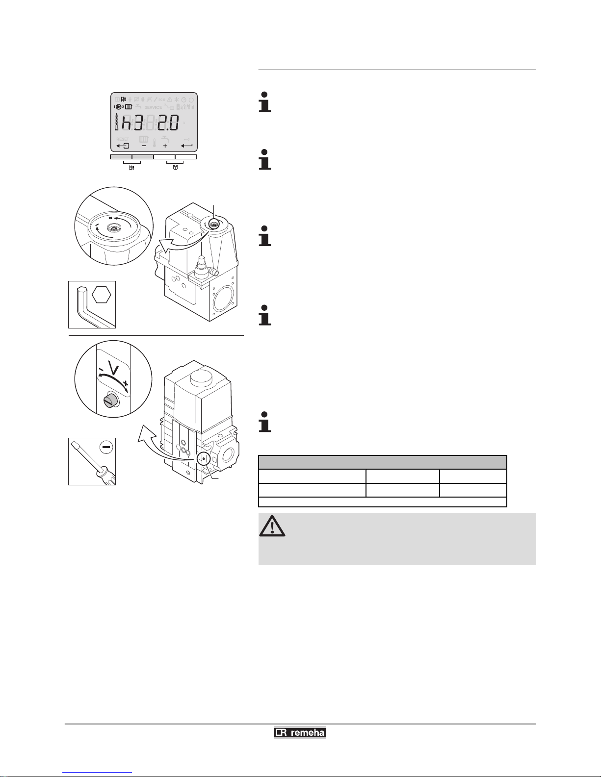
5.4.1. Setting the air/gas ratio (Full load)
For checking and/or setting the boiler Gas 610 ECO
PRO: The features and instructions described are for each
boiler module. Make sure that the other boiler module is
out of operation during this check and/or setting.
Measure the inlet gas pressure via the measuring point C
on the gas pipe. The pressure must be the same as the
one shown on the rating plate.
1. Unscrew the plug of the flue gas measurement point.
2. Connect the flue gas analyser.
Ensure that the opening around the sensor is completely
sealed when taking measurements.
3. Set the boiler to full load. Press the two B keys simultaneously.
The display shows
W3
. The symbol B appears.
4. Measure the percentage of O2 or CO2 in the flue gases.
The 5 to 9 section boilers are supplied with a different gas
block from the 10 section boiler. See drawing for the
position of control screw A for full load.
5. If this rate does not match the required value, correct the gas/air
ratio using the adjustment screw A on the gas valve unit. The
direction in which the adjustment screw must be turned to increase
or decrease the gas flow is indicated on the gas block.
6. Check the flame through the flame inspection window.
The flame must not be detached.
O2/CO2 control and setting values at full load for G20 (Gas H)
Gas 310 ECO PRO
O2 (%) CO2 (%)
All versions
4.3 - 4.8
(1)
9.0
(1)
- 9.3
(1) Nominal value
CAUTION
The CO2 values when operating at full load must be higher
than the values when operating at low load.
T004399-A
rpm
kWµA
± 30l/min
barPsi
St ºC
ºCºFh
T003480-G
O
A
A
3
5. Commissioning Gas 310 ECO PRO - Gas 610 ECO PRO
54
160514 - 125467-05
Page 57
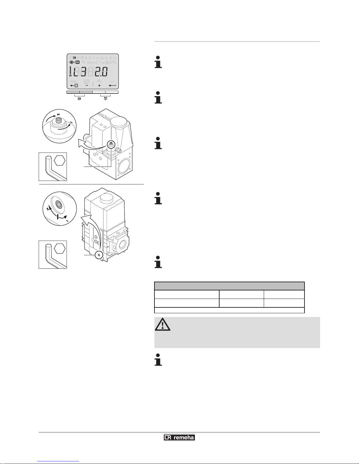
5.4.2. Setting the air/gas ratio (Part load)
For checking and/or setting the boiler Gas 610 ECO
PRO: The features and instructions described are for each
boiler module. Make sure that the other boiler module is
out of operation during this check and/or setting.
Measure the inlet gas pressure via the measuring point C
on the gas pipe. The pressure must be the same as the
one shown on the rating plate.
1. Unscrew the plug of the flue gas measurement point.
2. Connect the flue gas analyser.
Ensure that the opening around the sensor is completely
sealed when taking measurements.
3. Set the boiler to part load. Press the two B keys
simultaneously. The symbol B appears. Press the [-] key until
l3
is displayed.
4. Measure the percentage of O2 or CO2 in the flue gases.
The 5 to 9 section boilers are supplied with a different gas
block from the 10 section boiler. See drawing for the
position of control screw B for part load.
5. If this rate does not match the required value, correct the gas/air
ratio using the adjustment screw B on the gas valve unit. The
direction in which the adjustment screw must be turned to increase
or decrease the gas flow is indicated on the gas block.
6. Check the flame through the flame inspection window.
The flame must be stable.
O2/CO2 control and setting values at part load for G20 (Gas H)
Gas 310 ECO PRO
O2 (%) CO2 (%)
All versions
4.8
(1)
- 5.4 8.7 - 9,0
(1)
(1) Nominal value
CAUTION
The CO2 values when operating at low load must be lower
than the values when operating at full load.
T004391-A
rpm
kWµA
± 30l/min
barPsi
St ºC
ºCºFh
T003481-D
B
3
B
2.5
Gas 310 ECO PRO - Gas 610 ECO PRO 5. Commissioning
160514 - 125467-05
55
Page 58
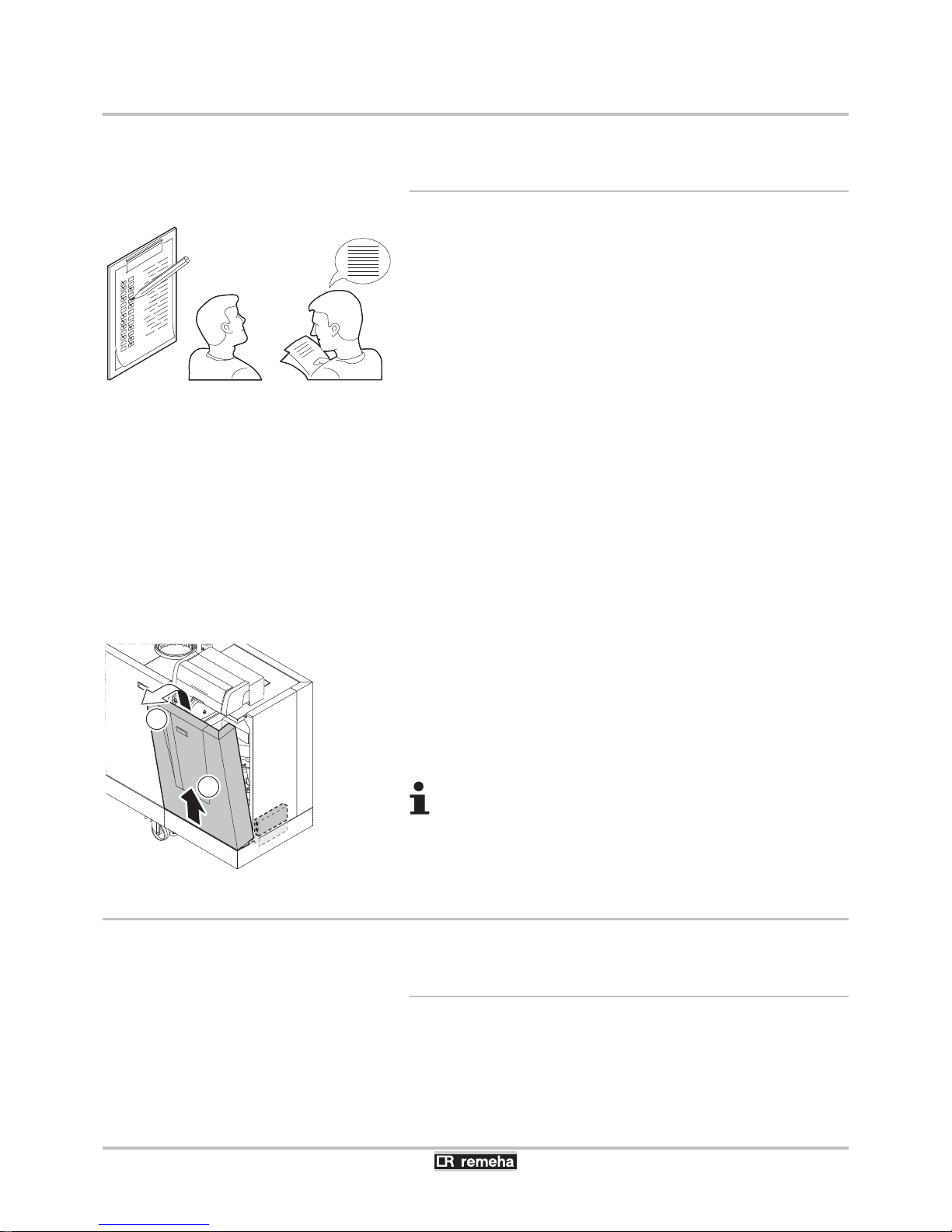
5.5 Checks and adjustments after commissioning
5.5.1. Finalizing work
1. Remove the measuring equipment.
2. Put the flue gas sampling plug back in place.
3. If installed: Check the setting of the minimum gas pressure switch
Gps. The pressure switch must be set at 10 mbar.
4. If installed: Check the setting of the pressure switch for gas
leakage control Vps. The pressure switch must be set at 50 % of
the admission pressure (Up to 40 mbar).
¼
See chapter: "Connection possibilities for the PCB (SCU-
S05)", page 42
5. Reapply the casing on the inspection side.
6. Push key
J
to return the boiler to normal operating mode.
7. Raise the temperature in the heating system to approximately
70°C.
8. Shut down the boiler.
9. After about 10 minutes, vent the air in the heating system.
10.Switch on the boiler.
11.Checking the hydraulic pressure. If necessary, top up the water
level in the heating system.
12.Tick the gas category used on the data plate.
13.Explain the operation of the installation, the boiler and the
regulator to the users.
14.Give all the instruction manuals to the user. A documentation
folder can be found in the frame of the boiler. Use it to store all
boiler manuals together with other documents relating to the
installation.
15.Finalizing work.
16.
Complete the checklist.
¼
See chapter: "Checklist for
commissioning", page 77.
The various boiler parameters are preset in the factory.
These factory settings are suitable for the most common
heating systems. For other systems and situations, the
parameters can be modified.
5.6 Reading out measured values
5.6.1. Reading the various current values
The following current values can be read off the information menu
Q:
4 5t = State.
4 5v = Sub-status.
T001522-A
T003979-E
2
1
5. Commissioning
Gas 310 ECO PRO - Gas 610 ECO PRO
56
160514 - 125467-05
Page 59

4 t1 = Flow temperature (°C).
4 t" = Return temperature (°C).
4 t4 = Outside temperature (°C)
Only with an outside temperature sensor (Accessory).
4 t6 = Exchanger temperature (°C).
4 5p = Internal set point (°C).
4 fl = Ionization current (µA).
4 Mf = Fan speed (rpm).
4 pr = Water pressure (bar (MPa)).
Only with the hydraulic pressure sensor connected (Accessory).
4 p; = Supplied relative heat output (%).
4 51 = Pressure switch minimum Gps (Kz = Not connected /
K1 = Gas pressure OK / K" = Gas pressure incorrect)
Only with connected minimum gas pressure switch (Accessory)
4 5" = Gas valve leak proving system Vps (Kz = Not
connected / K1 = No gas leak / K" = Gas leak present)
Only with connected gas leakage control (Accessory).
4 V1 = Analogue input (V).
4 V" = Analogue output (V).
¼See the Installation and service manual HMI GAS 310/610 ECO
PRO for comprehensive operating instructions. This includes
information about changing and reading parameters, the meaning of
fault codes and deleting the failure memory.
5.7 Changing the settings
The boiler control panel is set for the most common heating
systems. With these settings, practically all heating systems operate
correctly. The user or installer can optimise the parameters according
to own preferences.
¼See the Installation and service manual HMI GAS 310/610 ECO
PRO for comprehensive operating instructions. This includes
information about changing and reading parameters, the meaning of
fault codes and deleting the failure memory.
Gas 310 ECO PRO - Gas 610 ECO PRO 5. Commissioning
160514 - 125467-05
57
Page 60
6 Switching off the boiler
6.1 Installation shutdown
If the central heating system is not used for a long period, we
recommend switching the boiler off.
4 Switch the On/Off switch to Off.
4 Switch off the boiler electrical power supply.
4 Shut off the gas supply.
4 Ensure that the boiler and system are protected against frost
damage.
CAUTION
In the event of low temperatures, we recommend that the
installation continues to operate at a lower temperature.
This prevents freezing.
6.2 Antifreeze protection
CAUTION
Drain the boiler and central heating system if you are not
going to use your home or the building for a long time and
there is a chance of frost.
1. Set the temperature control low, for example at 10°C.
If there is no demand for heat, the boiler will only switch on in order
to prevent frost damage.
When the heating water temperature in the boiler falls by too much,
the integrated protection system in the boiler starts up. This protection
functions as follows:
(The circulation pump must be electrically connected to boiler)
4 The circulation pump switches on if the water temperature is lower
than 7°C.
4 If the water temperature is lower than 4°C, the boiler starts up.
4 If the water temperature is higher than 10°C, the boiler shuts down
and the circulation pump continues to run for a short time
CAUTION
The integrated protection system only protects the boiler,
not the installation.
6. Switching off the boiler Gas 310 ECO PRO - Gas 610 ECO PRO
58
160514 - 125467-05
Page 61
7 Checking and maintenance
7.1 General
The cast aluminium/silicon heat exchanger forms the heart of the
boiler. When combined with the special geometric shape, the flue gas
pollution remains limited. At the top of the heat exchanger, the space
between the pins of the heated surface on the flue gas side is slightly
larger than further down. This ensures quick distribution of the hot flue
gases over the heat exchanger which avoids an excessive load at the
top. Due to the boiler’s modulating operation, condensation occurs in
different locations in the heat exchanger. This ensures that most of
the oxidation residues produced are dissolved and rinsed away. The
self-cleaning operation therefore functions optimally.
Nevertheless, we recommend cleaning the flue gas side of the heat
exchanger thoroughly during the annual inspection and service.
Adjust the frequency of inspection and service to the
conditions of use. This applies especially to boilers in
constant use (for specific processes).
7.2 Standard checks
For work on the boiler Gas 610 ECO PRO: The features
and instructions described are for each boiler module.
CAUTION
During inspection and maintenance operations, always
replace all gaskets on the parts removed.
When it is observed subsequent to inspection or
maintenance work that a component in the boiler needs to
be replaced, use only original spare parts or recommended
spare parts and equipment. A service set containing all
necessary components is available for standard
maintenance.
We recommend carrying out the standard checks in the following
order:
1. Checking the hydraulic pressure.
2. Checking the ionization current.
3. Check the water quality.
4. Checking the air supply connections and flue gas discharge
connections.
5. Checking the gas filter for pollution.
6. Checking combustion.
7. Check the air supply hose.
8. Check the dirt trap.
9. Check the air box.
Gas 310 ECO PRO - Gas 610 ECO PRO
7. Checking and maintenance
160514 - 125467-05
59
Page 62
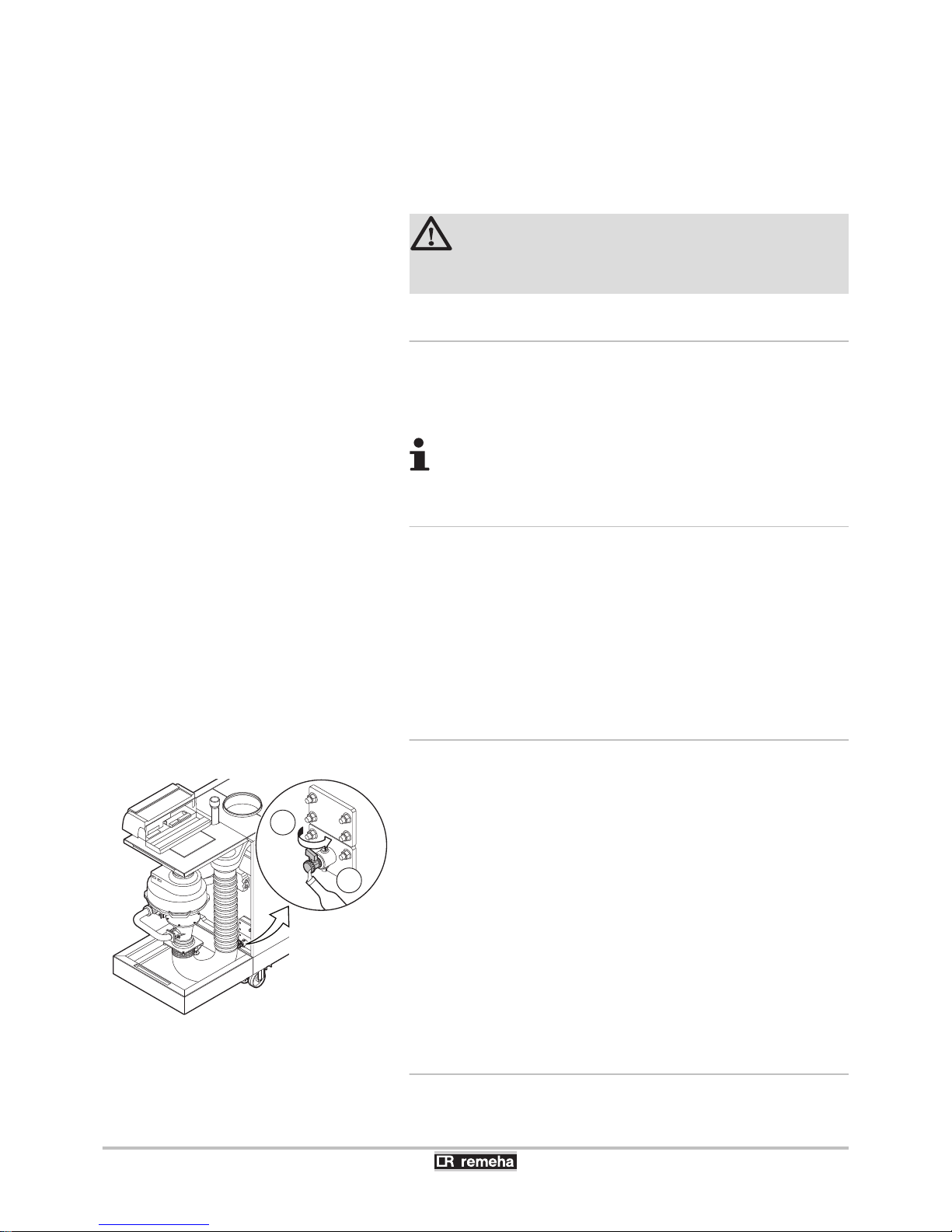
10.Check the air pressure differential switch PS.
11.If installed: Check the gas leakage control VPS.
12.If installed: Check the minimum gas pressure switch Gps.
Preparation
First heat the boiler on high for about 5 minutes (return temperature
65ºC) to dry the heat exchanger on the flue gas side.
WARNING
Always wear safety goggles during cleaning work (using
compressed air).
7.2.1. Checking the hydraulic pressure
The hydraulic pressure must reach a minimum of 0.8 bar. If the water
pressure is lower than 0.8 bar, the symbol e will appear. Only with
the hydraulic pressure sensor connected (Accessory).
If the water pressure is lower than 0,8 bar, more water
should be added.
7.2.2. Checking the ionization current
Check the ionization current at full load and low load. The value is
stable after 1 minute. If the value lies below 3 µA, replace the ignition
electrode.
¼See the Installation and service manual HMI GAS 310/610 ECO
PRO for comprehensive operating instructions. This includes
information about changing and reading parameters, the meaning of
fault codes and deleting the failure memory.
7.2.3. Check the water quality
1. Fill a clean bottle with water from the installation/boiler via the
filling and drain cock.
2. Check the quality of this water sample or have it checked.
For more information, refer to our publication water quality rules. This
manual forms a part of the documentation supplied with the boiler.
The rules in the aforementioned document must be respected.
7.2.4. Checking the air supply connections and
flue gas discharge connections
Check the condition and tightness of the flue gas discharge and air
supply connection.
T004854-A
1
2
7. Checking and maintenance
Gas 310 ECO PRO - Gas 610 ECO PRO
60
160514 - 125467-05
Page 63
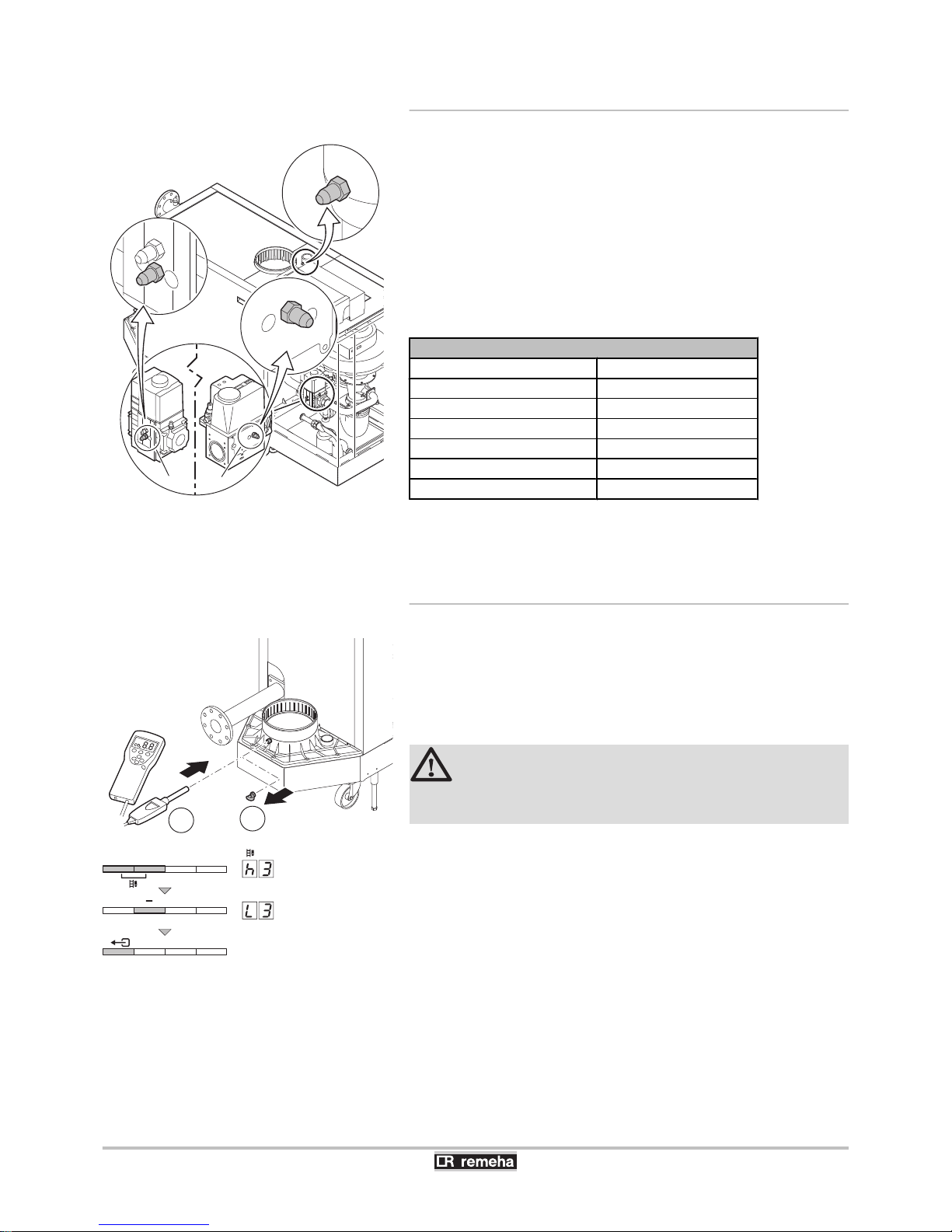
7.2.5. Checking the gas filter for pollution
The gas block on the boiler is fitted with a gas filter as standard. Check
this for pollution.
1. Set the boiler to full load.
2. Measure the inlet gas pressure via the measuring point P1 on the
gas pipe (It should be at least 17 mbar).
3. Check the gas supply pressure at the pressure outlet 2 on the gas
valve unit.
4. Compare the values measured with the checking values given in
the table:
Inlet gas pressure minimum values 2 on the gas block
Gas 310 ECO PRO
Minimum value
285 14 mbar
355 13 mbar
430 10 mbar
500 10 mbar
575 10 mbar
650 10 mbar
5. If the measured value is lower than the control value, clean or
replace the gas filter.
7.2.6. Checking combustion
The check on combustion is done by measuring the percentage of
O2/CO2 in the flue gas discharge flue.
1. Unscrew the plug of the flue gas measurement point.
2. Insert the measuring sensor of the flue gas analyser in the opening
of the flue gas measuring point.
CAUTION
Ensure that the opening around the sensor is completely
sealed when taking measurements.
3. Set the boiler to full load. Press the two B keys simultaneously.
The B symbol is visible on the menu bar and
W3
appears in the
display. The boiler is now operating at full load.
4. Measure the percentage of CO2 and compare this value with the
checking values given.
¼
See chapter: "Setting the air/gas ratio (Full load)", page
54.
5. Set the boiler to part load. Press the [-] key until
l3
is
displayed. The boiler is now operating on part load.
6. Measure the percentage of CO2 and compare this value with the
checking values given.
¼
See chapter: "Setting the air/gas ratio (Part load)", page
55.
7. Remove the measuring sensor of the flue gas analyser from the
opening of the flue gas measuring point.
T003774-K
22
10
5/6/7/8/9
3
2
P
P1
2
T004852-A
2
1
T004354-A
...x
Gas 310 ECO PRO - Gas 610 ECO PRO
7. Checking and maintenance
160514 - 125467-05
61
Page 64
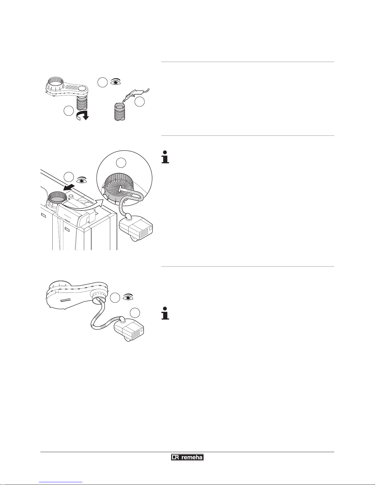
8. Put the flue gas sampling plug back in place.
7.2.7. Check the air supply hose
1. Disconnect the pipe on the air box side by loosening the bayonet
fitting.
2. Check the hose for damage and pollution.
3. Remove the pollution from the hose with a cloth or soft brush.
4. Replace the hose if it is faulty and/or leaking.
7.2.8. Check the dirt trap
4 With room sealed operation, disconnect the air supply
pipe above the boiler to access the dirt trap.
4 In room ventilated operation with an air supply filter,
remove the filter to access the dirt trap.
1. Check the dirt trap on the air supply side for pollution.
2. First remove coarse pollution and clean the trap with a vacuum
cleaner or a cloth.
7.2.9. Check the air box
1. Check the air box for pollution.
2. Clean the dirty air box using a vacuum cleaner. Do this from the
connection opening for the air supply hose.
If the air box is dirty, the following components must also
be dismantled and cleaned with compressed air:
4 Non-return valve.
4 Venturi.
4 Fan.
T004855-A
1
2
3
T004853-B
1
2
T004856-B
1
2
7. Checking and maintenance Gas 310 ECO PRO - Gas 610 ECO PRO
62
160514 - 125467-05
Page 65
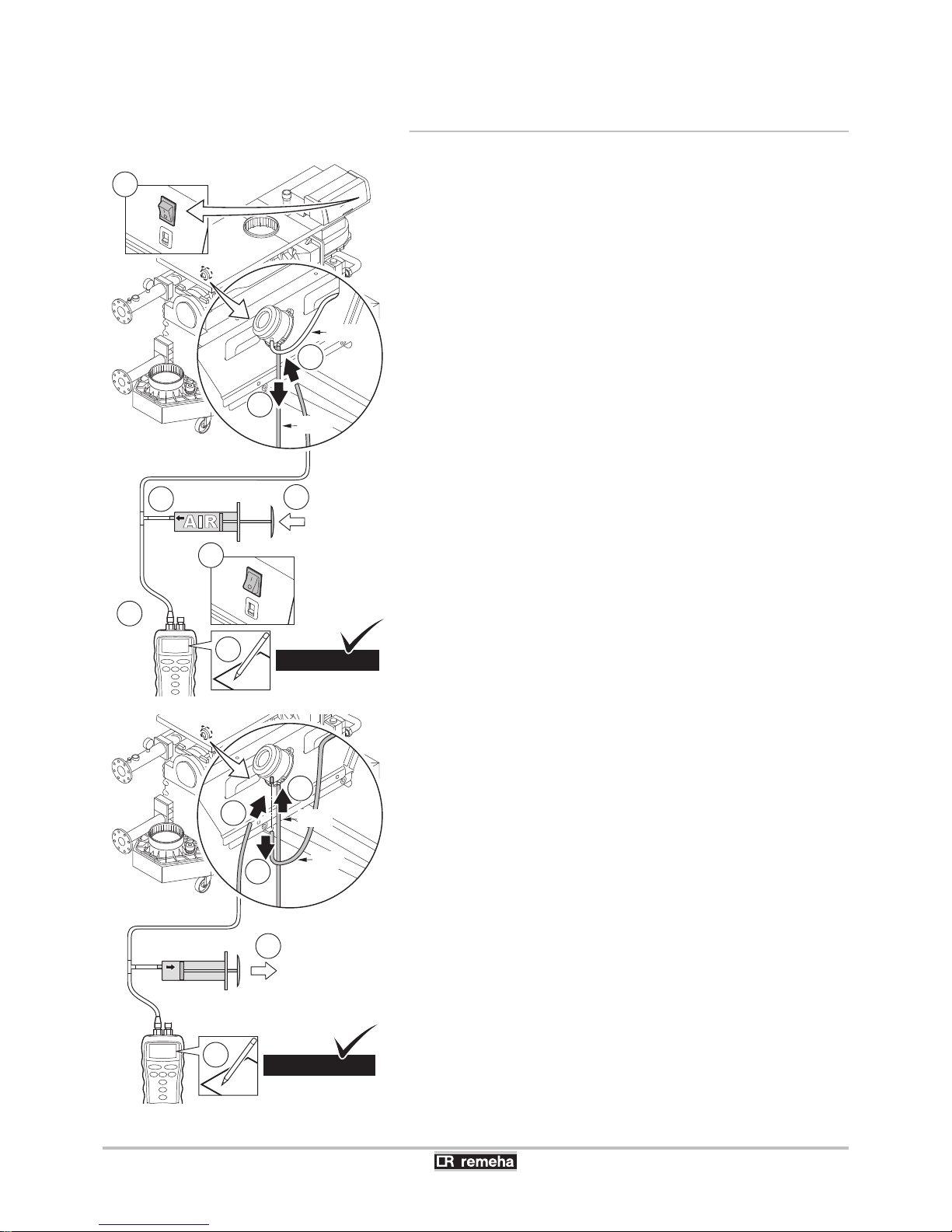
7.2.10. Check the air pressure differential switch
PS
Check the air pressure differential switch +
1. Switch the boiler off.
2. Disconnect the silicon hose on the + side (P1) of the air pressure
differential switch.
3. Take a large plastic syringe and connect a T piece with a hose
connected to the mouth.
4. Connect the + side of the air pressure differential switch to one
end of the T piece with a hose.
5. On the other end of the T piece, connect the + side of a pressure
gauge.
6. Switch on the boiler.
7. Push the syringe in very slowly until the boiler goes into failure
mode; Code
e12
.
8. Make a note of the pressure indicated by the pressure gauge at
that point. A switch pressure of between 5.5 mbar and 6.5 mbar is
fine. A lower or higher switch pressure indicates a problem with
the air pressure differential switch.
Check the air pressure differential switch -
1. Fasten the silicon hose on the + side (P1) of the air pressure
differential switch.
2. Disconnect the silicon hose on the - side (P2) of the air pressure
differential switch.
3. Connect the - side of the air pressure differential switch to one end
of the T piece with a hose.
4. Pull out the syringe until the boiler goes into failure mode; Code
e12
.
5. Make a note of the pressure indicated by the pressure gauge at
that point. A switch pressure of between - 5.5 mbar and - 6.5
mbar is fine. A lower or higher switch pressure indicates a problem
with the air pressure differential switch.
6. Remove any pollution from the connection points of hoses on the
air pressure differential switch.
7. Check the condition and tightness of the hoses of the air pressure
differential switch. Replace the hoses if necessary.
T005045-C
SLOW
(+)
7
3
5
1
P
1
(+)
2
4
P
2
(-)
X mbar
6
........ mb
ar
8
5.5 mbar....6,5
T005046-A
SLOW
4
P
1
(+)
1
2
3
P
2
(-)
X mbar
........ mb
ar
5
-5.5 mbar....-6,5
(+)
Gas 310 ECO PRO - Gas 610 ECO PRO
7. Checking and maintenance
160514 - 125467-05
63
Page 66
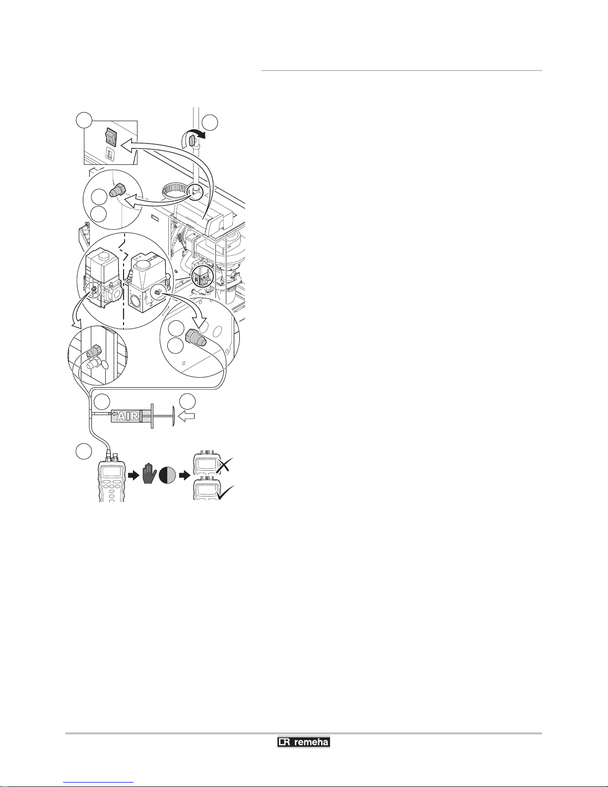
7.2.11. Check the gas leakage control VPS
A - Leak test
1. Switch the boiler off.
2. Close the boiler gas cock.
3. Remove the pressure from the gas pipe by unscrewing the screw
in measuring point P1.
4. As soon as the gas pipe is pressure-free, retighten the screw.
5. Open the screw in measuring point 3 of the gas block (On the
opposite side of the VPS pressure switch).
6. Take a large plastic syringe and connect a T piece with a hose
connected to the mouth.
7. Connect one end of the T piece to measuring point 3 of the gas
block.
8. Connect the other end of the T piece to a pressure gauge.
9. Push the syringe in very slowly until the pressure gauge indicates
the minimum inlet gas pressure value.
10.Check the measured pressure for about 30 seconds. If pressure
decreases by more than half, this indicates a gas leak.
11.Replace the gas block or the VPS if necessary.
T005263-D
10
5/6/7/8/9
3
5
7
2
P
P1
3
4
2
9
SLOW
(+)
8
X mbar
30 sec
≥ 0.5 x
≤ 0.5 x
1
3
6
7. Checking and maintenance Gas 310 ECO PRO - Gas 610 ECO PRO
64
160514 - 125467-05
Page 67
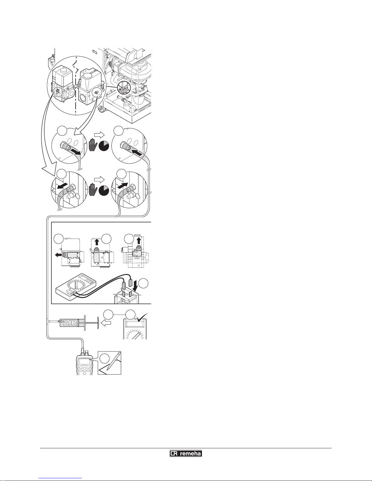
B - Check the switch value
1. "Remove the pressure from the gas block; to do so remove the
hose connected to measuring point 3 of the gas block" (On the
opposite side of the VPS pressure switch).
2. Wait approximately 10 seconds and reconnect the disconnected
hose to measuring point 3 of the gas block.
3. Remove the connecting plug from the VPS gas leakage control.
4. Connect an ohmmeter to terminals 2 and 3 of the VPS.
5. Push the syringe in very slowly until the ohmmeter indicates 0
Ohm.
6. Make a note of the pressure indicated by the pressure gauge at
that point. If the measured pressure differs by more than 2 mbar
from the VPS set-up value, set the pressure switch to the correct
value or replace it.
T005264-C
3
2
1
10
5/6/7/8/9
SLOW
(+)
X mbar
........ mb
ar
6
VPS
GPS
VPS GPS
3 3
5/6 7/8/9 10
3
2
4
GPS
VPS
0 Ohm
5 5
10 sec
10 sec
3
2
2
3
313
2
Gas 310 ECO PRO - Gas 610 ECO PRO 7. Checking and maintenance
160514 - 125467-05
65
Page 68
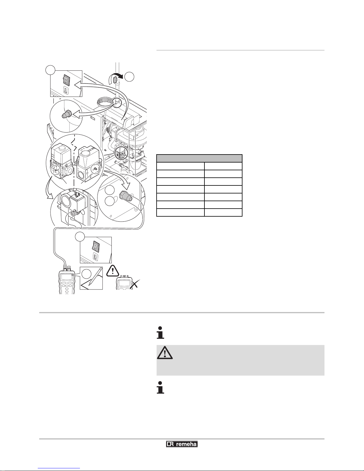
7.2.12. Check the minimum gas pressure switch
Gps
1. Switch the boiler off.
2. Open the screw in measuring point 2 of the gas block.
3. Connect a pressure gauge to measuring point 2 of the gas block.
4. Switch on the boiler.
5. Set the boiler to low load.
6. Close the boiler gas cock very slowly until the boiler shuts down;
Code
5t[9
.
7. Make a note of the pressure indicated by the pressure gauge at
that point. Compare the values measured with the checking values
given in the table. If the measured pressure is lower, set the gas
pressure switch to the correct value or replace it.
Pressure switch minimum
Gas 310 ECO PRO
Minimum value
285 14 mbar
355 13 mbar
430 10 mbar
500 10 mbar
575 10 mbar
650 10 mbar
7.3 Specific maintenance operations
For work on the boiler Gas 610 ECO PRO: The features
and instructions described are for each boiler module.
CAUTION
During inspection and maintenance operations, always
replace all gaskets on the parts removed.
After a service complete the checklist.
If the standard inspection and maintenance operations have revealed
the necessity to carry out additional maintenance work, proceed as
follows, depending on the nature of the work:
T005265-D
P1
6
3
2
P
3
2
(+)
X mbar
........ mb
ar
7
≤ 10.0
1
10
5/6/7/8/9
2 2
2
4
7. Checking and maintenance
Gas 310 ECO PRO - Gas 610 ECO PRO
66
160514 - 125467-05
Page 69
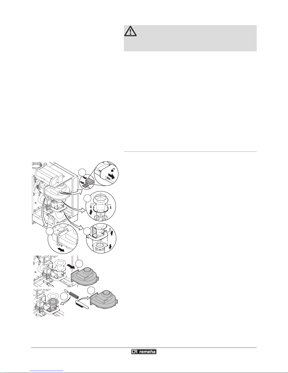
DANGER
4 Disconnect the appliance’s electricity supply.
4 Shut off the gas supply.
We recommend carrying out the specific maintenance activities in the
following order:
1. Clean the fan and the venturi.
2. Clean and inspect the non-return valve.
3. Replacing the ionization/ignition electrode.
4. Cleaning the gas filter.
5. Clean and inspect the burner.
6. Clean the burner area.
7. Cleaning the heat exchanger.
8. Cleaning the condensate collector.
9. Cleaning the siphon.
10.Assembling the boiler.
11.Put the boiler back into operation.
7.3.1. Clean the fan and the venturi
1. Remove the electrical connections from the fan. Push the safety
slides on both sides of the power plug right to the back (You could
use a small screwdriver for example).
2. Unscrew the bolts from the extension piece under the fan. Support
the gas block, using a block of wood, for example.
3. Disconnect the air inlet hose from the venturi.
4. Unscrew the nuts on the fan output.
5. Disconnect the fan from the adapter.
6. Clean the fan with a soft plastic brush.
7. Clean the venturi with a soft plastic brush.
T003494-J
2
1
3
6
7
5
4
Gas 310 ECO PRO - Gas 610 ECO PRO 7. Checking and maintenance
160514 - 125467-05
67
Page 70
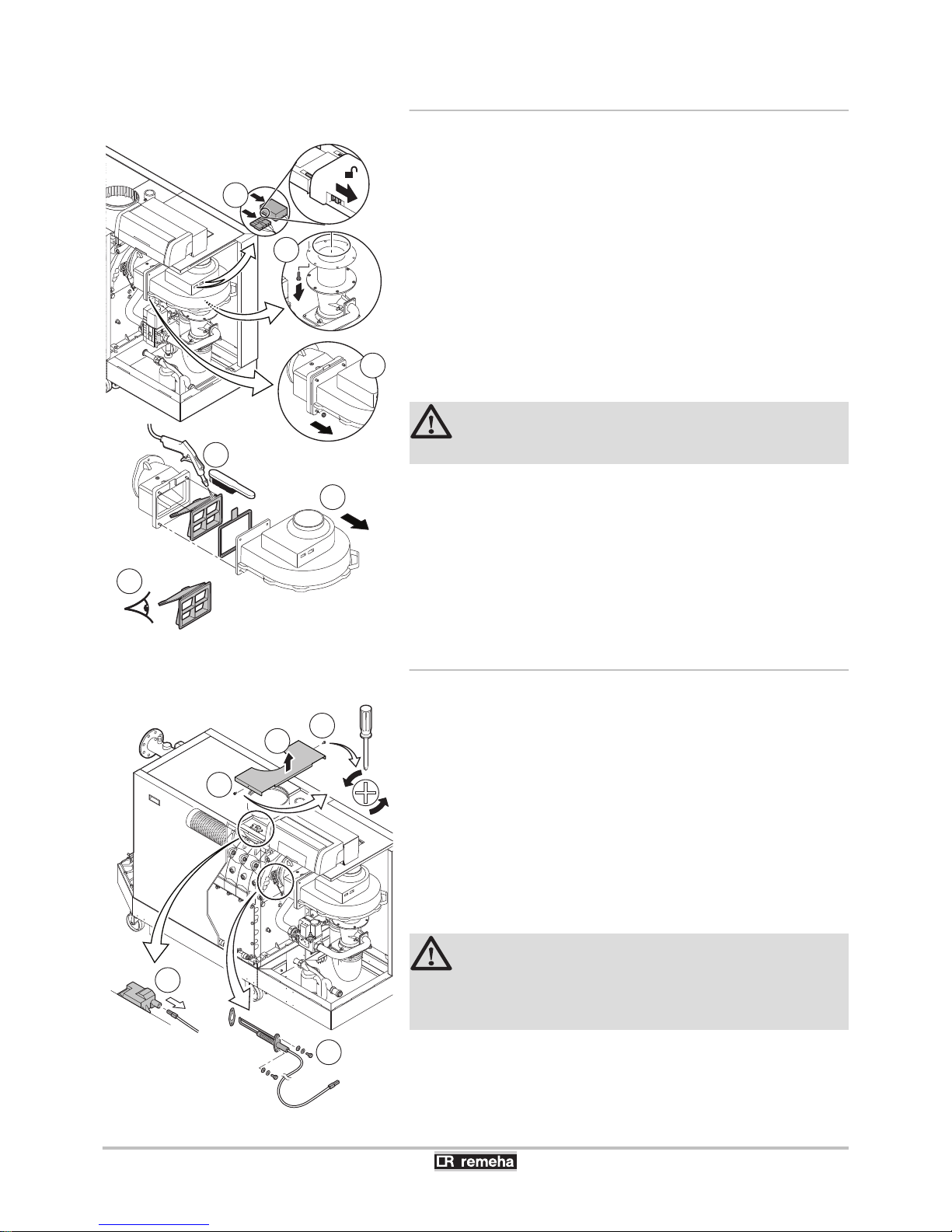
7.3.2. Clean and inspect the non-return valve
The non return valve must be replaced if it is faulty.
1. Remove the electrical connections from the fan. Push the safety
slides on both sides of the power plug right to the back (You could
use a small screwdriver for example). Support the gas block, using
a block of wood, for example.
2. Unscrew the bolts from the extension piece under the fan.
3. Unscrew the nuts on the fan output.
4. Disconnect the fan from the adapter.
5. Clean the non-return valve with a soft plastic brush or with
compressed air.
6. Inspect the non-return valve and replace it if faulty or seriously
damaged.
7. To re-assemble, perform the above actions in reverse order.
CAUTION
Reconnect the fan’s electrical connection.
7.3.3. Replacing the ionization/ignition electrode
Replace the ionization/ignition electrode in the following cases:
4 Ionization current <3 µA.
4 The electrode is damaged or worn (Visual inspection).
If replacement is necessary, proceed as follows:
1. Unscrew the 2 screws on the middle top casing.
2. Remove the middle top casing.
3. Remove the cable from the ionization/ignition electrode on the
ignition transformer.
4. Unscrew the 2 screws and remove the ionization/ignition
electrode.
CAUTION
Do not fit the new ionisation/ignition electrode until the
burner has been cleaned and refitted. This will prevent
damage occurring.
.
T003493-H
4
5
1
2
3
6
T003490-H
1
1
2
3
4
7. Checking and maintenance
Gas 310 ECO PRO - Gas 610 ECO PRO
68
160514 - 125467-05
Page 71
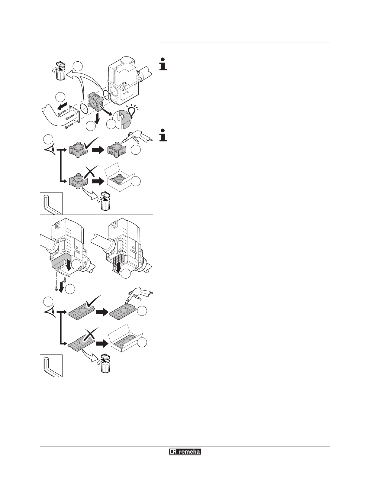
7.3.4. Cleaning the gas filter
The 5 to 9 section boilers are supplied with a different gas
block from the 10 section boiler.
1. Remove the gas filter.
2. Inspection.
3. Clean the gas filter without the use of liquids (shake it or carefully
blow it clean).
4. Replace the gas filter if necessary.
5. To re-assemble, perform the above actions in reverse order.
In this gas block, the gas filter holder has a positioning
ridge. Position this at the top left during assembly.
T004043-B
4mm
3mm
1a 4x
2
2
1a 2x
1b
1c
1b
1c
5
4
3
4
3
Gas 310 ECO PRO - Gas 610 ECO PRO 7. Checking and maintenance
160514 - 125467-05
69
Page 72
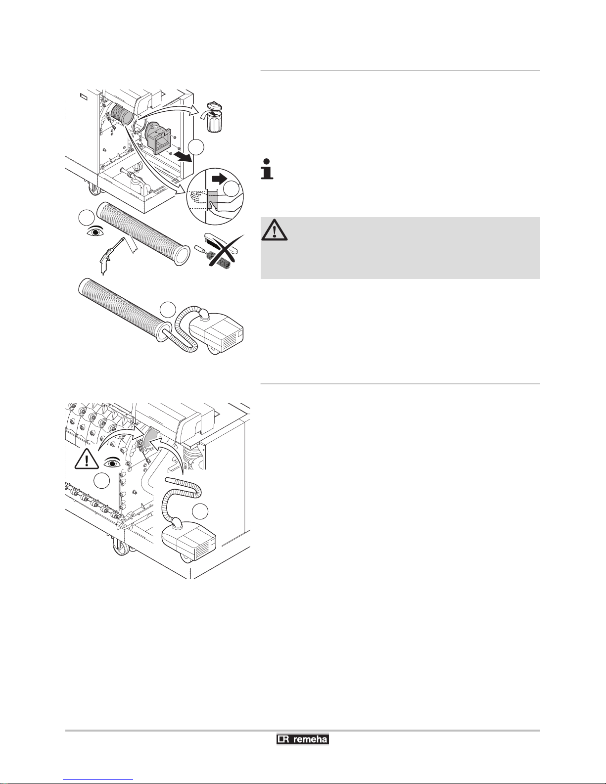
7.3.5. Cleaning the burner
1. Unscrew the nuts from the adapter: Remove the adapter.
2. Lift the burner out of the heat exchanger.
3. Check the burner and, if necessary, clean without touching it (e.g.
with compressed air between 2 and 5 bars: respect a minimum
distance of 1 cm from the surface of the burner).
Never clean the burner’s surface with a brush or similar
item.
4. Carefully hoover the dirt from the inside of the burner.
5. Replace the burner if faulty or seriously damaged.
CAUTION
Do not refit the burner until the burner area, heat
exchanger, condensate collector and siphon have been
cleaned.
7.3.6. Clean the burner area
1. Perform a visual check of the burner area.
2. Remove visible pollution with a vacuum cleaner.
T003488-F
1
2
2-5 bar
min. 1cm
3
4
1
2
T005044-A
7. Checking and maintenance Gas 310 ECO PRO - Gas 610 ECO PRO
70
160514 - 125467-05
Page 73
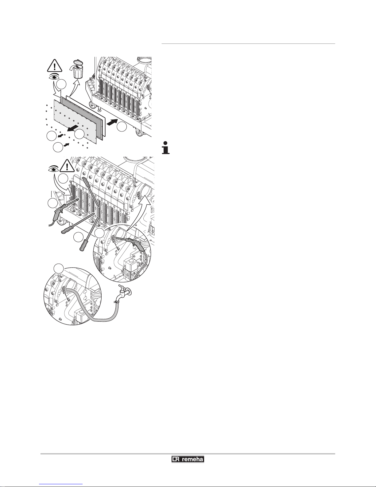
7.3.7. Checking the heat exchanger
1. Unscrew the nuts from the inspection hatch on the heat
exchanger.
2. Take the inspection hatch off the heat exchanger and remove the
insulation cloth. The insulation cloth may stick to the heat
exchanger. Avoid damaging or tearing the insulation cloth.
Remove the silicon insulation cord.
3. Inspect the insulation cloth and replace if necessary.
4. Clean the areas between the pins of the heat exchanger using the
special cleaning tool or cleaning knife (Accessory). Always work
from the bottom to the top. Move the cleaning knife between the
pins horizontally and diagonally.
A range of cleaning knives is available for the various
boilers. Always use the cleaning knife specially designed
for this boiler. This knife has a length of 560 mm.
5.
Use compressed air to blow the cleaned parts through in turn. Do
this from the service side and from the burner area.
6. Fit the inspection hatch with the silicon cord and the insulation
cloth.
7. Use clean water to thoroughly rinse the heat exchanger from the
burner area.
T003491-G
6
1
6
2
3
4
4
5
5
7
Gas 310 ECO PRO - Gas 610 ECO PRO 7. Checking and maintenance
160514 - 125467-05
71
Page 74
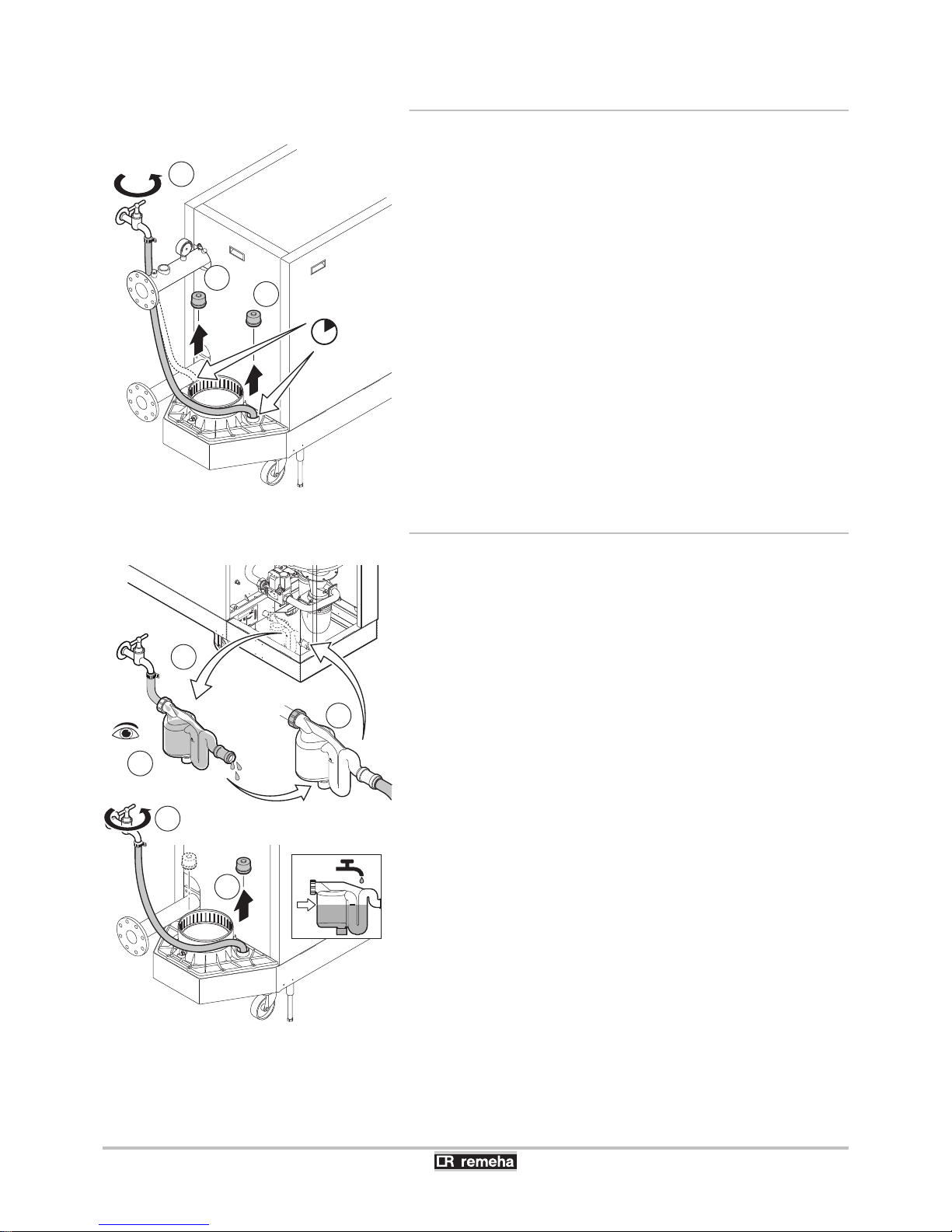
7.3.8. Cleaning the condensate collector
1. Remove both sealing caps from the condensate collector. (In front
of and behind the flue gas discharge connection).
2. Thoroughly clean the condensate collector with water. Rinse each
side of the condensate collector for at least 5 minutes with the
largest possible water flow.
3. Refit both sealing caps on the condensate collector.
7.3.9. Cleaning the siphon
1. Remove the siphon.
2. Clean the siphon with water.
3. Put the siphon back in place.
4. Fill the siphon with water via the condensate tank (Up the level
marker).
T004851-A
1
2
1
min.
5 min.
T003478-K
4
1
2
3
4
7. Checking and maintenance Gas 310 ECO PRO - Gas 610 ECO PRO
72
160514 - 125467-05
Page 75
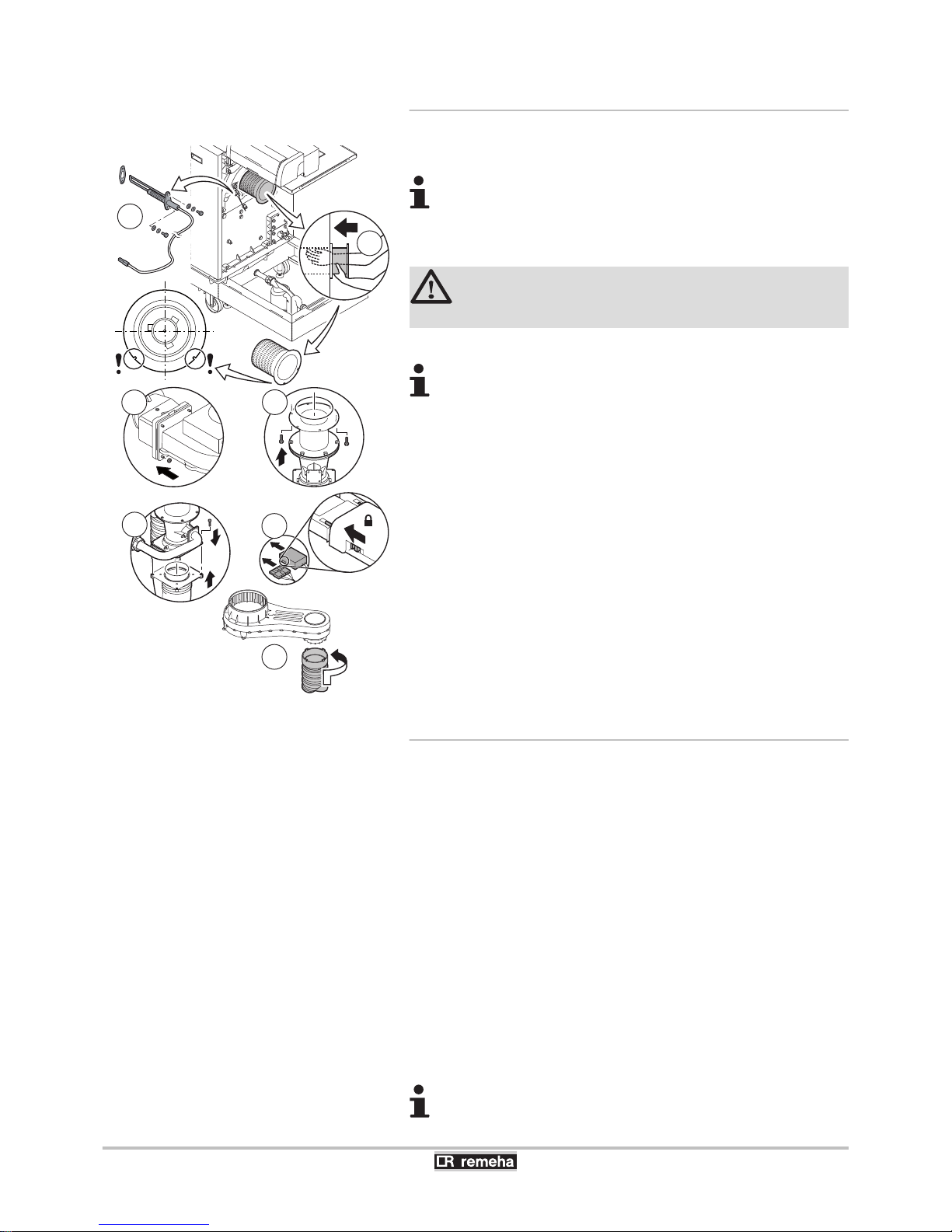
7.3.10. Assembling the boiler
1. Fit the burner.
The burner has 2 holes at the front. Position it on the 2
support pins at the burner opening.
2. Fit the new ionisation/ignition electrode.
3. Fit the venturi and the fan.
CAUTION
Reconnect the fan’s electrical connection.
4. Fit the air supply hose.
After a service complete the checklist.
7.3.11. Put the boiler back into operation
1. Open the main gas supply.
2. Check the gas circuit.
3. Checking the hydraulic pressure.
4. Check that there are no leaks on the hydraulic connections.
5. Checking the flue gas discharge and the air supply.
6. Check the electricity supply.
7. Check the electrical connections.
8. Turn on the boiler using the on/off switch.
9. Check the gas supply pressure at the pressure outlet P2 on the
gas valve unit.
10.Check the ionization current.
11.Check the combustion.
12.Check the gas connections between the gas block and the venturi
for tightness.
13.Bleed the Central Heating system.
After a service complete the checklist.
T004857-C
1
2
3
3
3
3
4
Gas 310 ECO PRO - Gas 610 ECO PRO 7. Checking and maintenance
160514 - 125467-05
73
Page 76
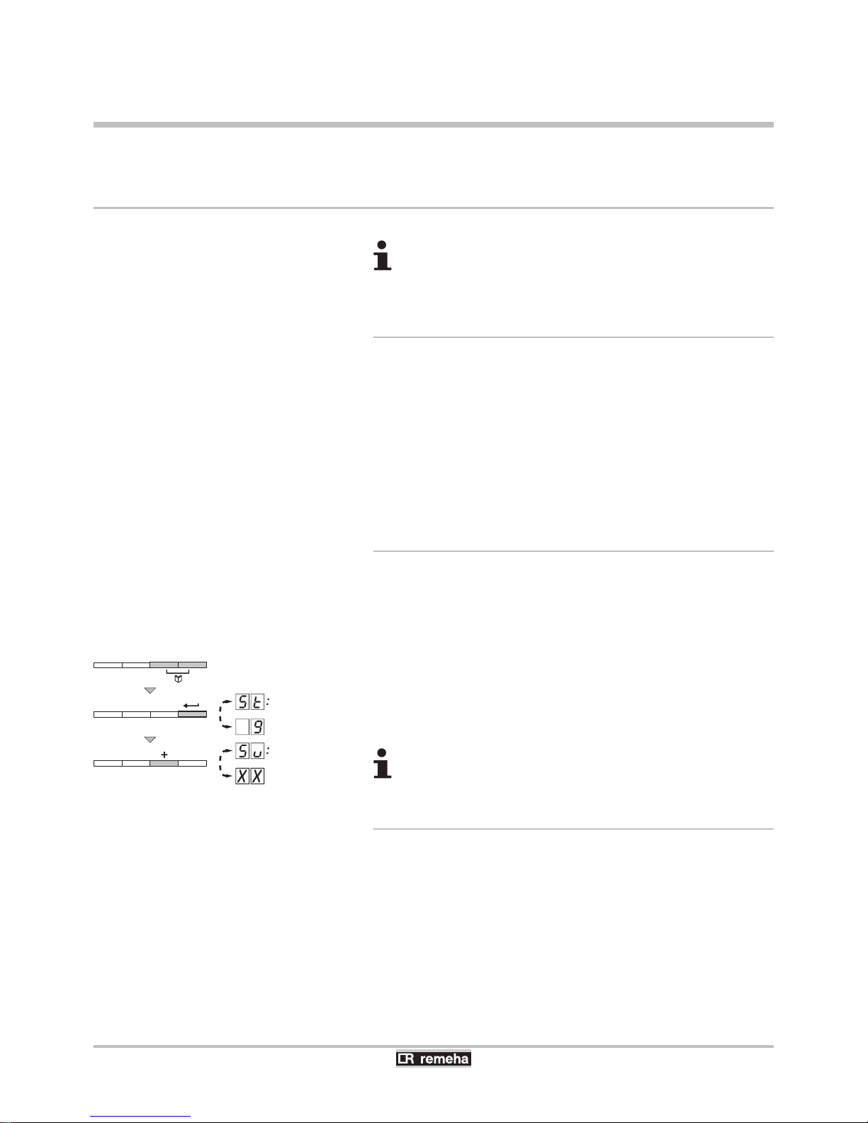
8 Troubleshooting
8.1 Shutdowns and lock-outs
For operation of the boiler Gas 610 ECO PRO: The
features and instructions described are for each boiler
module.
8.1.1. General
The boiler is fitted with an electronic regulation and control unit. The
heart of the control system is a microprocessor, the Comfort
Master©, which controls the boiler and also protects the boiler. When
a failure is signalled, the boiler stops or becomes locked.
¼See the Installation and service manual HMI GAS 310/610 ECO
PRO for comprehensive operating instructions. This includes
information about changing and reading parameters, the meaning of
fault codes and deleting the failure memory.
8.1.2. Blocking
A (temporary) blocking mode is a boiler operating function caused by
an unusual situation. In this case, the display gives a code of blocking
(code 5t[9). The boiler control will try to re-start several times.
The shutdown codes can be read out as follows
1. Press the two f keys simultaneously.
2. Confirm by pressing key S.
5t
is displayed, alternating with
the shutdown code 9.
3. Press the [+] key.
5v
appears on the display.
The boiler starts up again automatically when the reason
for the blocking has been removed.
8.1.3. Lock out
When a failure is signalled, the boiler stops or becomes locked. The
display shows :
In a red flashing display:
4 The symbol c
4 The symbol J
4 The fault code (for example e[01)
T001632-B
8. Troubleshooting
Gas 310 ECO PRO - Gas 610 ECO PRO
74
160514 - 125467-05
Page 77

The boiler can only start operating again once the causes
of the lock-out have been rectified and after pressing the
J key
8.1.4. Error memory
The boiler control is equipped with an error memory. The last 10 errors
encountered are recorded in this memory. Each new input deletes the
oldest entry from the memory. In addition to the error codes, the
following data are also saved:
4 Number of times that the error occured: (MK[xx).
4 Boiler operating mode selected (5t[xx).
4 The flow temperature (t1[xx) and the return temperature
(t2[xx) when the error occured.
Gas 310 ECO PRO - Gas 610 ECO PRO 8. Troubleshooting
160514 - 125467-05
75
Page 78
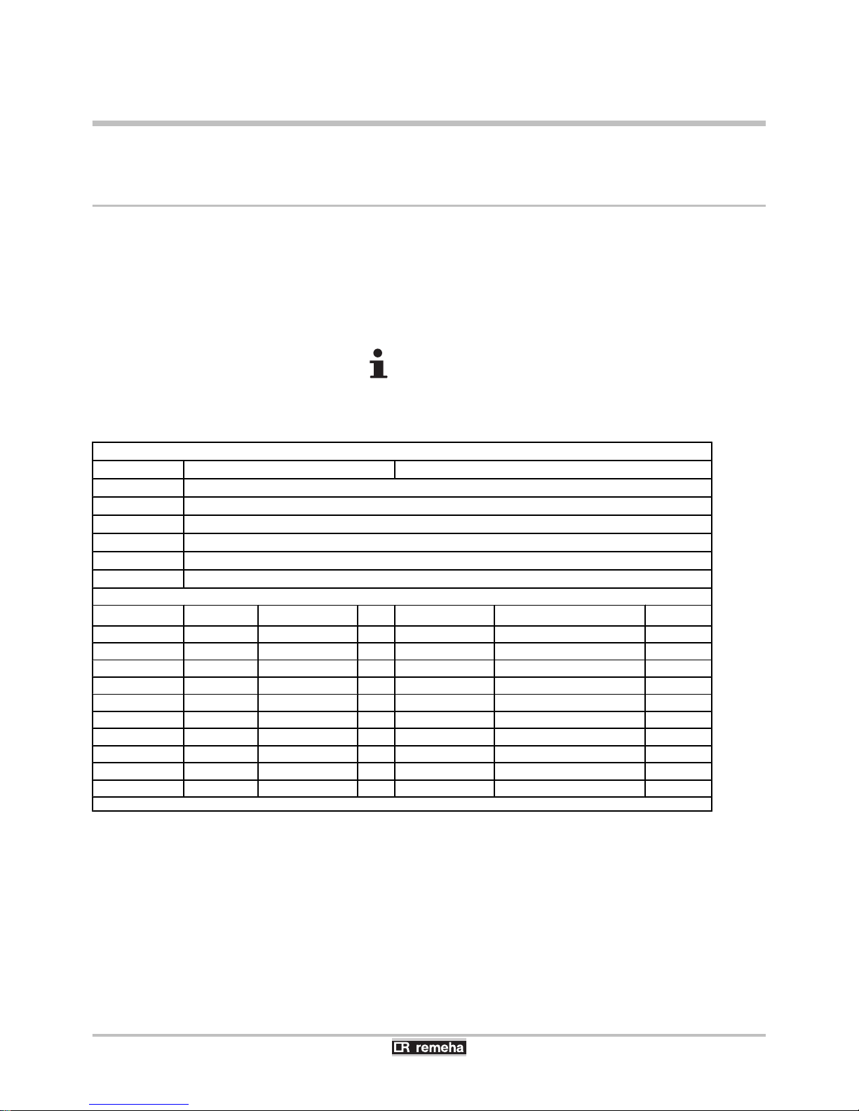
9 Spare parts
9.1 General
When it is observed subsequent to inspection or maintenance work
that a component in the boiler needs to be replaced, use only original
spare parts or recommended spare parts and equipment.
Send the component to be replaced to your supplier’s Returned
Goods Department if the component in queston is under warranty
(see general terms and conditions of sale and delivery).
Always ensure that your return package is accompanied
by the completed return form, see attached example. In this
way, your supplier can fulfil his warranty obligations more
easily and more effectively.
Customer
Reference
Date
Name
Address
Town/Postcode
Telephone
Contact person
Order number
Code no. Description
Serial number
(1)
Type Installation date Reason for the exchange Reference
(1) This information can be found on the rating plate.
9. Spare parts Gas 310 ECO PRO - Gas 610 ECO PRO
76
160514 - 125467-05
Page 79
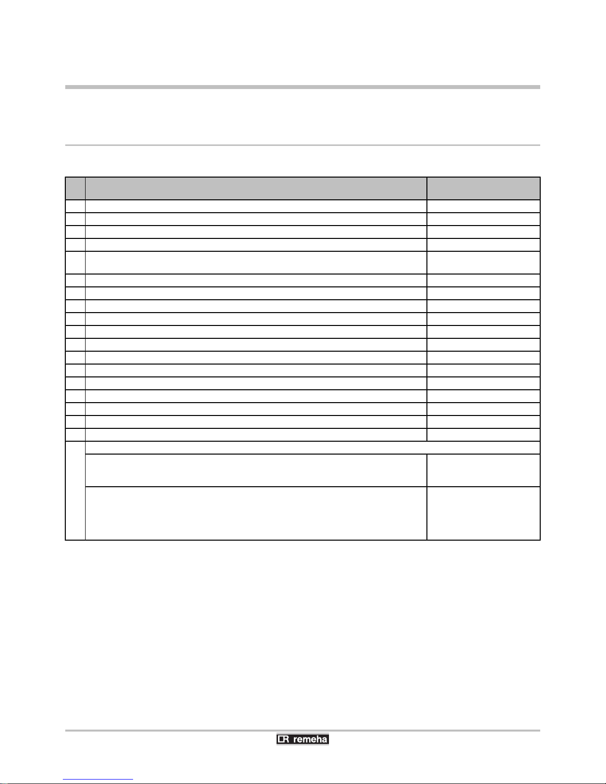
10 Checklists
10.1 Checklist for commissioning
No. Work to be undertaken for commissioning Confirmation / Measured
values
1 Filling the central heating system with water and checking the water pressure
2 Fill the siphon with water
3 Vent the air in the heating system
4 Checking the water-side connections for tightness
5 Checking the type of gas supplied. Checking that the boiler is suitable for the gas
supplied?
6 Checking the gas supply pressure
7 Checking the capacity of the gas meter
8 Checking the tightness of the connections and the gas pipes
9 Purge the gas supply pipe of the boiler
10 Checking the electrical connections
11 Checking the air supply connections and flue gas discharge connections
12 Checking the functioning and operational status of the boiler
13 Checking the air/gas ratio
14 Remove the measuring device and close the measurement points
15 Attaching the Gas Type sticker
16 Reapply the casing on the inspection side
17 Set the boiler regulation to the desired values
18 Instruct the user and hand over the necessary documents
19 Confirmation of commissioning
Date (dd-mm-yy)
Company name, signature of engineer
Gas 310 ECO PRO - Gas 610 ECO PRO 10. Checklists
160514 - 125467-05
77
Page 80
10.2 Checklist for periodic inspection and maintenance
No. Inspection and/or service activities Confirmation and date
1 Checking the hydraulic pressure
2 Checking the ionization current
3 Check the water quality
4 Checking the air supply connections and flue gas
discharge connections
5 Checking the gas filter for pollution
6 Checking combustion (CO2) (Full load/Part load)
7 Check the air supply hose
8 Check the dirt trap
9 Check the air box
10 Check the air pressure differential switch PS
11 Check the gas leakage control VPS
(If installed)
12 Check the minimum gas pressure switch GPS
(If installed)
13 Clean the fan and the venturi
14 Clean and inspect the non-return valve
15 Replacing the ionization/ignition electrode
17 Cleaning the gas filter
16 Clean and inspect the burner
18 Clean the burner area
19 Cleaning the heat exchanger
20 Cleaning the condensate collector
21 Cleaning the siphon
22 Assembling the boiler (Replace all removed gaskets)
23 Put the boiler back into operation
24 Confirmation of inspection
Date (dd-mm-yy) (dd-mm-yy) (dd-mm-yy) (dd-mm-yy) (dd-mm-yy)
Company name, signature of engineer
10. Checklists Gas 310 ECO PRO - Gas 610 ECO PRO
78
160514 - 125467-05
Page 81

Gas 310 ECO PRO - Gas 610 ECO PRO 10. Checklists
160514 - 125467-05
79
Page 82

10. Checklists Gas 310 ECO PRO - Gas 610 ECO PRO
80
160514 - 125467-05
Page 83

Page 84
Remeha Commercial UK - Part of the BDR THERMEA
Remeha House
Molly Millars Lane
Wokingham
Berks
RQ41 2QP
After Sales Tel: 01189743076
Technical Enquires: 01189743067
Internet: www.remeha.co.uk
© Copyright
All technical and technological information contained in these technical instructions,
as well as any drawings and technical descriptions supplied, remain our property
and shall not be multiplied without our prior consent in writing.
160514
125467
 Loading...