

REMEHA CALORA TOWER GAS 15S EX, CALORA TOWER GAS 25S EX, CALORA TOWER GAS 35S EX Installation And Service Manual
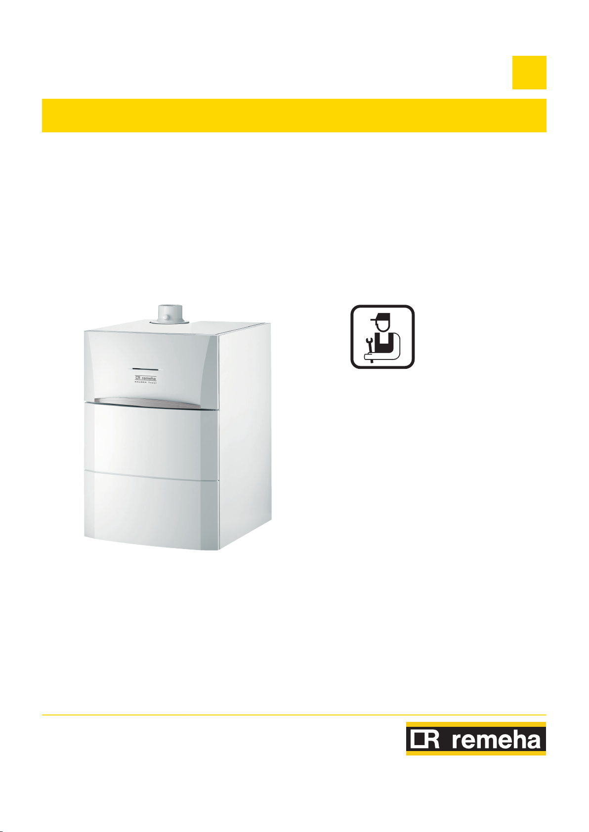
Floor-standing high efficiency gas boiler
C003589-A
CALORA TOWER GAS 15S EX
CALORA TOWER GAS 25S EX
CALORA TOWER GAS 35S EX
EN
Installation and
Service Manual
300026141-001-07

Declaration of conformity
The device complies with the standard type described in
the EG declaration of conformity. It was manufactured and
commissioned in accordance with European directives.
The original declaration of conformity is available from the
manufacturer.

Contents
1 Safety instructions and recommendations ..............................................6
1.1 General safety instructions .................................6
1.2 Recommendations ................................................7
1.3 Liabilities ...............................................................8
1.3.1 Manufacturer’s liability .............................................8
1.3.2 Installer’s liability .....................................................8
2 About this manual ......................................................................................9
2.1 Symbols used .......................................................9
2.1.1 Symbols used in the manual ...................................9
2.1.2 Symbols used on the equipment .............................9
2.2 Abbreviations ......................................................10
3 Technical specifications ..........................................................................11
3.1 Homologations ....................................................11
3.1.1 Certifications .........................................................11
3.1.2 Gas categories ......................................................11
3.1.3 Additional Directives ..............................................11
3.1.4 Factory test ...........................................................11
3.2 Technical specifications ....................................11
4 Technical description ..............................................................................13
4.1 General description ............................................13
4.2 Main parts ............................................................13
4.3 Operating principle .............................................14
4.3.1 Skeleton Diagrams ................................................14
4.3.2 Circulation pump ...................................................15
4.3.3 Water flow rate ......................................................16
5 Installation ................................................................................................17
22/04/2016 - 300026141-001-07
5.1 Regulations governing installation ...................17
5.2 Package list .........................................................17
5.2.1 Standard delivery ..................................................17
5.2.2 Accessories ...........................................................17
5.3 Choice of the location ........................................18
5.3.1 Type plate .............................................................18
1

Contents
5.3.2 Positioning of the appliance ..................................19
5.3.3 Ventilation .............................................................20
5.3.4 Main dimensions ...................................................21
5.4 Positioning the appliance ..................................25
5.4.1 Positioning the boiler on its own ............................25
5.4.2 Fitting the boiler to a DHW tank ............................27
5.4.3 Positioning the boiler to the left or right of a DHW
tank .......................................................................28
5.5 Hydraulic connections .......................................28
5.5.1 Flushing the system ..............................................28
5.5.2 Hydraulic connection of the heating circuit ............29
5.5.3 Connection of the water circuit for domestic
use ........................................................................29
5.5.4 Connecting the expansion vessel .........................29
5.5.5 Connecting the condensate discharge pipe ..........30
5.5.6 Filling the condensate trap ....................................31
5.6 Gas connection ...................................................31
5.7 Flue gas system connections ............................32
5.7.1 Classification .........................................................32
5.7.2 Lengths of the air/flue gas pipes ...........................33
5.8 Electrical connections ........................................35
5.8.1 Control unit ............................................................35
5.8.2 Recommendations ................................................35
5.8.3 Access to the connection terminal ........................36
5.8.4 Position of the PCBs .............................................38
5.8.5 Heating circuit with boiler alone ............................38
5.8.6 Connecting a direct heating circuit and a domestic hot
water tank ..............................................................39
5.9 Optional electrical connections ........................42
5.9.1 Position of the optional PCBs ................................42
5.9.2 Position of the connections on the PCU
board .....................................................................43
5.9.3 c-Mix PCB .............................................................43
5.9.4 0-10 V (IF-01) PCB ...............................................44
5.9.5 Connection possibilities for the PCB (SCU-
S02) .......................................................................46
5.9.6 Connection possibilities for the PCB (SCU-
S03) .......................................................................49
5.9.7 Connection possibilities for the PCB (SCU-
X01) .......................................................................50
5.10 Electrical diagram ...............................................52
5.11 Filling the system ...............................................53
5.11.1 Water treatment ....................................................53
5.11.2 Filling the system ..................................................53
6 Commissioning ........................................................................................55
6.1 Control panel .......................................................55
6.1.1 Functions of the keys ............................................55
22/04/2016 - 300026141-001-07
2

6.1.2 Meaning of the symbols on the display .................55
6.2 Check points before commissioning ................56
6.2.1 Preparing the boiler for commissioning .................56
6.2.2 Gas circuit .............................................................56
6.2.3 Hydraulic circuit .....................................................58
6.2.4 Electrical connections ...........................................58
6.3 Putting the appliance into operation ................58
6.4 Gas settings ........................................................60
6.4.1 Adapting to another gas type ................................60
6.4.2 Checking and setting combustion .........................60
6.4.3 Basic setting for the gas/air ratio ...........................64
6.5 Checks and adjustments after
commissioning ...................................................64
6.5.1 Finalizing work ......................................................64
6.6 Reading out measured values ...........................65
6.6.1 Reading out measured values ..............................65
6.6.2 Readout from the hour counter and percentage of
successful starts ....................................................67
6.6.3 Status and sub-status ...........................................67
6.7 Changing the settings ........................................68
6.7.1 Parameter descriptions .........................................68
6.7.2 Modification of the installer-level parameters ........73
6.7.3 Setting the maximum heat input for central heating
operation ...............................................................73
6.7.4 Return to the factory settings Reset Param ..........74
6.7.5 Carrying out an auto-detect ...................................75
7 Switching off the appliance .....................................................................76
7.1 Installation shutdown .........................................76
7.2 Antifreeze protection ..........................................76
8 Checking and maintenance .....................................................................77
8.1 Preventive maintenance with automated service
message ..............................................................77
8.1.1 Resetting the automatic maintenance
message ................................................................77
8.1.2 Dealing with the next maintenance message and
starting the new maintenance period ....................78
22/04/2016 - 300026141-001-07
8.2 Standard inspection and maintenance
operations ...........................................................78
8.2.1 Checking the hydraulic pressure ...........................78
8.2.2 Checking the expansion vessel .............................79
8.2.3 Checking the ionization current .............................79
8.2.4 Checking the tightness of the flue gas evacuation and
air inlet connections ..............................................79
8.2.5 Checking combustion ............................................79
3

Contents
8.2.6 Checking the automatic air vent ............................80
8.2.7 Checking the safety valve .....................................80
8.2.8 Checking the condensate trap ..............................80
8.2.9 Checking the burner and cleaning the heat
exchanger .............................................................81
9 Troubleshooting .......................................................................................82
9.1 Error codes ..........................................................82
9.2 Shutdowns and lock-outs ..................................87
9.2.1 Lock out .................................................................87
9.2.2 Blocking .................................................................87
9.3 Error memory ......................................................90
9.3.1 Error readout memorised ......................................91
9.3.2 Deletion of the error display ..................................92
10 Spare parts ................................................................................................93
10.1 General ................................................................93
10.2 Spare parts ..........................................................94
10.2.1 Casing ...................................................................94
10.2.2 Water unit ..............................................................95
10.2.3 Control panel .........................................................96
10.2.4 Casing ...................................................................96
10.2.5 Spare parts list ......................................................97
11 Appendix – Information on the Ecodesign and Energy Labelling
Directives ..................................................................................................99
22/04/2016 - 300026141-001-07
4

22/04/2016 - 300026141-001-07
5
1. Safety instructions and recommendations CALORA TOWER GAS 15S EX CALORA TOWER GAS 25S EX
CALORA TOWER GAS 35S EX
1 Safety instructions and
recommendations
1.1 General safety instructions
DANGER
This appliance can be used by children aged
from 8 years and above and persons with
reduced physical, sensory or mental capabilities
or lack of experience and knowledge if they have
been given supervision or instruction concerning
use of the appliance in a safe way and
understand the hazards involved. Children shall
not play with the appliance. Cleaning and user
maintenance shall not be made by children
without supervision.
DANGER
If you smell gas:
1. Do not use a naked flame, do not smoke, do
not operate electrical contacts or switches
( doorbell, light, motor, lift, etc..).
2. Shut off the gas supply.
3. Open the windows.
4. Trace possible leaks and seal them
immediately.
5. If the gas leak is before the gas meter,
contact the gas supplier.
DANGER
If you smell flue gases:
1. Switch the appliance off.
2. Open the windows.
3. Trace possible leaks and seal them
immediately.
6
22/04/2016 - 300026141-001-07

CALORA TOWER GAS 15S EX CALORA TOWER GAS 25S EX
CALORA TOWER GAS 35S EX
1.2 Recommendations
1. Safety instructions and recommendations
WARNING
4 Installation and maintenance of the boiler
must be carried out by a qualified
professional in compliance with prevailing
local and national regulations.
4 When working on the boiler, always
disconnect the boiler from the mains and
close the main gas inlet valve.
4 After maintenance or repair work, check all
installations to ensure that there are no
leaks.
CAUTION
The boiler must be installed in a frost-free
environment.
Keep this document close to the place where the
boiler is installed.
Casing components
Only remove the casing for maintenance and repair
operations. Put the casing back in place after
maintenance and repair operations.
Instructions stickers
The instructions and warnings affixed to the appliance
must never be removed or covered and must remain
legible during the entire lifespan of the appliance.
Immediately replace damaged or illegible instructions and
warning stickers.
Modifications
Modifications may only be made to the boiler after the
written permission of Remeha to do so.
22/04/2016 - 300026141-001-07
7

1. Safety instructions and recommendations
1.3 Liabilities
CALORA TOWER GAS 15S EX CALORA TOWER GAS 25S EX
CALORA TOWER GAS 35S EX
1.3.1. Manufacturer’s liability
Our products are manufactured in compliance with the
requirements of the various applicable European
Directives. They are therefore delivered with [ marking
and all relevant documentation.
In the interest of customers, we are continuously
endeavouring to make improvements in product quality.
All the specifications stated in this document are therefore
subject to change without notice.
Our liability as the manufacturer may not be invoked in the
following cases:
4 Failure to abide by the instructions on using the
appliance.
4 Faulty or insufficient maintenance of the appliance.
4 Failure to abide by the instructions on installing the
appliance.
1.3.2. Installer’s liability
The installer is responsible for the installation and
commissioning of the appliance. The installer must
respect the following instructions:
4 Read and follow the instructions given in the manuals
provided with the appliance.
4 Carry out installation in compliance with the prevailing
legislation and standards.
4 Perform the initial start up and carry out any checks
necessary.
4 Explain the installation to the user.
4 If a maintenance is necessary, warn the user of the
obligation to check the appliance and maintain it in
good working order.
4 Give all the instruction manuals to the user.
8
22/04/2016 - 300026141-001-07
D000241-C
CALORA TOWER GAS 15S EX CALORA TOWER GAS 25S EX
CALORA TOWER GAS 35S EX
2 About this manual
2.1 Symbols used
2.1.1. Symbols used in the manual
In these instructions, various danger levels are employed to draw the
user’s attention to particular information. In so doing, we wish to
safeguard the user’s safety, highlight hazards and guarantee correct
operation of the appliance.
2. About this manual
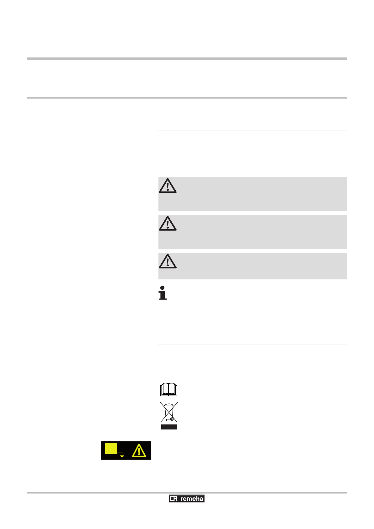
DANGER
Risk of a dangerous situation causing serious physical
injury.
WARNING
Risk of a dangerous situation causing slight physical
injury.
CAUTION
Risk of material damage.
Signals important information.
¼Signals a referral to other instructions or other pages in the
instructions.
2.1.2. Symbols used on the equipment
4
~
Protective earthing
Alternating current
Before installing and commissioning the device, read
carefully the instruction manuals provided.
Dispose of the used products in an appropriate recovery
and recycling structure.
22/04/2016 - 300026141-001-07
This appliance must be connected to the protective earth.
9
1 2
M002628-A
2. About this manual CALORA TOWER GAS 15S EX CALORA TOWER GAS 25S EX
CALORA TOWER GAS 35S EX
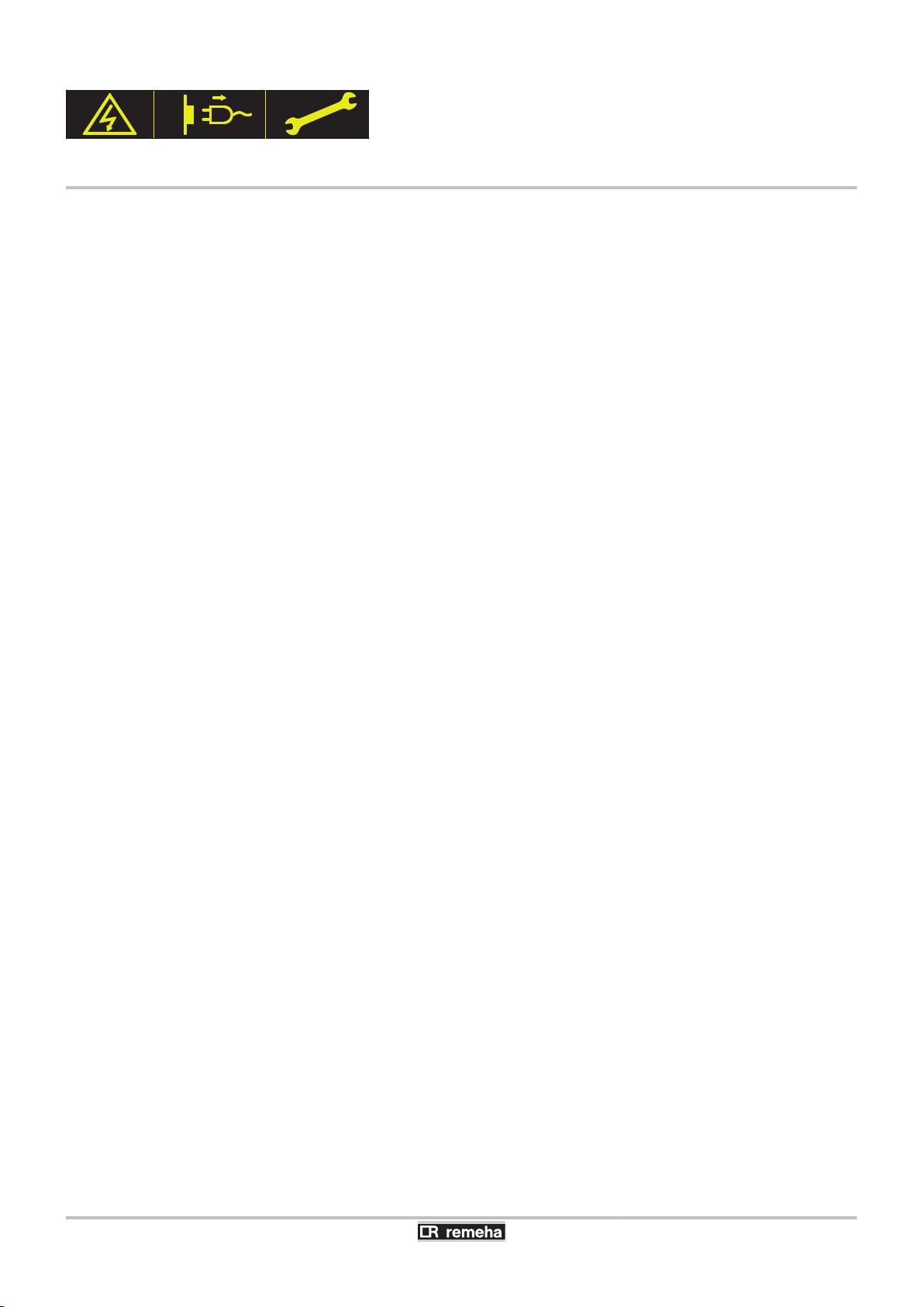
Caution: danger, live parts.
Disconnect the mains power prior to any operations.
2.2 Abbreviations
4 3CE: Collective conduit for sealed boiler
4 DHW: Domestic hot water
4 HRU: Heat Recovery Unit
4 HL: High Load - DHW tank with plate exchanger
4 SL: Standard Load - DHW tank with coil
4 SHL: Solar High Load - Solar DHW tank with plate exchanger
10
22/04/2016 - 300026141-001-07
CALORA TOWER GAS 15S EX CALORA TOWER GAS 25S EX
CALORA TOWER GAS 35S EX
3 Technical specifications
3.1 Homologations
3.1.1. Certifications
3. Technical specifications
CE identification no
NOx classification
Type of connection
(Flue gas outlet)
CE-0085CM0178
5 (EN 15502-1, EN 15502-2-1)
B23, B
, B33, C13, C33, C43, C53, C63, C83, C
23P
93
3.1.2. Gas categories
Gas category
II
2H3P
Gas type Connection pressure (mbar)
G20 (Gas H) 20
G31 (Propane) 37/50
3.1.3. Additional Directives
Apart from the legal provisions and Directives, the additional
Directives described in these instructions must also be observed.
For all provisions and Directives referred to in these instructions, it is
agreed that all addenda or subsequent provisions will apply at the
time of installation.
3.2 Technical specifications
22/04/2016 - 300026141-001-07
3.1.4. Factory test
Before leaving the factory, each boiler is set for optimum performance
and tested to check the following items:
4 Electrical safety
4 Adjustment (CO2)
4 Domestic hot water mode
4 Water tightness
4 Gas tightness
4 Parameter settings
11
3. Technical specifications CALORA TOWER GAS 15S EX CALORA TOWER GAS 25S EX
CALORA TOWER GAS 35S EX
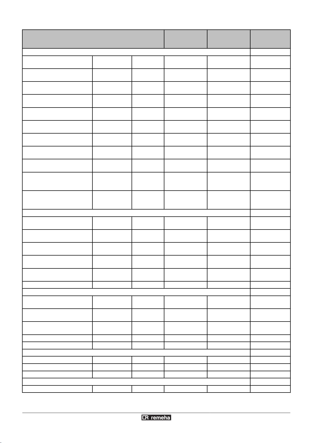
Boiler type CALORA TOWER
GAS 15S EX
General
Nominal output (Pn)
Heating System (80/60 °C)
Nominal output (Pn)
Heating System (50/30 °C)
Nominal output (Pn)
Heating System (40/30 °C)
Nominal input (Qn)
Heating System (Hi)
Nominal input (Qn)
Heating System (Hs)
Nominal input (Qnw)
DHW System (Hi)
Nominal input (Qnw)
DHW System (Hs)
Heating efficiency under full
load (Hi) (80/60 °C)
Heating efficiency under full
load (Hi) (50/30 °C)
Heating efficiency under partial
load (Hi) (Return temperature
60°C)
Heating efficiency under partial
load (EN 92/42) (Return
temperature 30°C)
Data on the gases and combustion gases
Gas consumption - Natural gas
H (G20)
Gas consumption - Natural gas
L (G25)
Gas consumption - Propane
G31
Mass flue gas flow rate minimum-
Flue gas temperature minimum-
Maximum counter pressure
Characteristics of the heating circuit
Water content (ex expansion
vessel)
Water operating pressure minimum kPa (bar
Water operating pressure
(PMS)
Water temperature maximum °C 110 110 110
Operating temperature maximum °C 90 90 90
Electrical characteristics
Power supply voltage
Power consumption - Full load maximum W 101 116 132
Electrical protection index
Other characteristics
Weight (empty)
minimummaximum
minimummaximum
minimummaximum
minimummaximum
minimummaximum
minimummaximum
minimummaximum
- % 99,3 99,2 99,1
- % 105,3 102,0 102,2
- % 94,9 96,1 96,3
- % 110,2 110,1 110,6
minimummaximum
minimummaximum
minimummaximum
maximum
maximum
maximum kPa (bar
kW 3,0 - 14,9 5,0 - 24,8 6,3 - 34,8
kW 3,4 - 15,8 5,6 - 25,5 7,0 - 35,9
kW 3,4 - 16,0 5,6 - 25,9 7,0 - 36.4
kW 3,1 - 15,0 5,2 - 25,0 6,5 - 35,1
kW 3,4 - 16,7 5,8 - 27,8 7,2 - 39,0
kW 3,1 - 15,0 5,2 - 29,3 6,5 - 35,1
kW 3,4 - 16,7 5,8 - 32,6 7,2 - 39,0
m3/h
m3/h
m3/h
kg/h 5,3 - 25,2 8,9 - 49,3 11,1 - 57,3
°C 30 - 65 30 - 80 30 - 75
Pa 80 130 140
l 1,9 1,9 2,5
(MPa))
(MPa))
VAC 230 230 230
kg 56 59 59
0,33 - 1,59 0,55 - 3,10 0,69 - 3,71
0,38 - 1,85 0,64 - 3,61 0,80 - 4,32
0,13 - 0,61 0,21 - 1,20 0,27 - 1,44
80 (0,8) 80 (0,8) 80 (0,8)
300 (3,0) 300 (3,0) 300 (3,0)
IP21 IP21 IP21
CALORA TOWER
GAS 25S EX
CALORA
TOWER GAS
35S EX
12
22/04/2016 - 300026141-001-07
C003072-C
18
19
16
17
15
14
13
12
11
1234
10
9
5
6
7
8
CALORA TOWER GAS 15S EX CALORA TOWER GAS 25S EX
CALORA TOWER GAS 35S EX
4 Technical description
4.1 General description
Gas fired floor-standing condensing boiler
4 High efficiency heating.
4 Low pollutant emissions.
4 Optional domestic hot water production in combination with a
DHW tank.
The boiler is fitted with an interior light. The interior light
comes on in the following cases:
4 The boiler is switched on: The lighting is switched on
for 10 minutes.
4 The boiler is switched off: The lighting is switched on
for 30 minutes.
4. Technical description
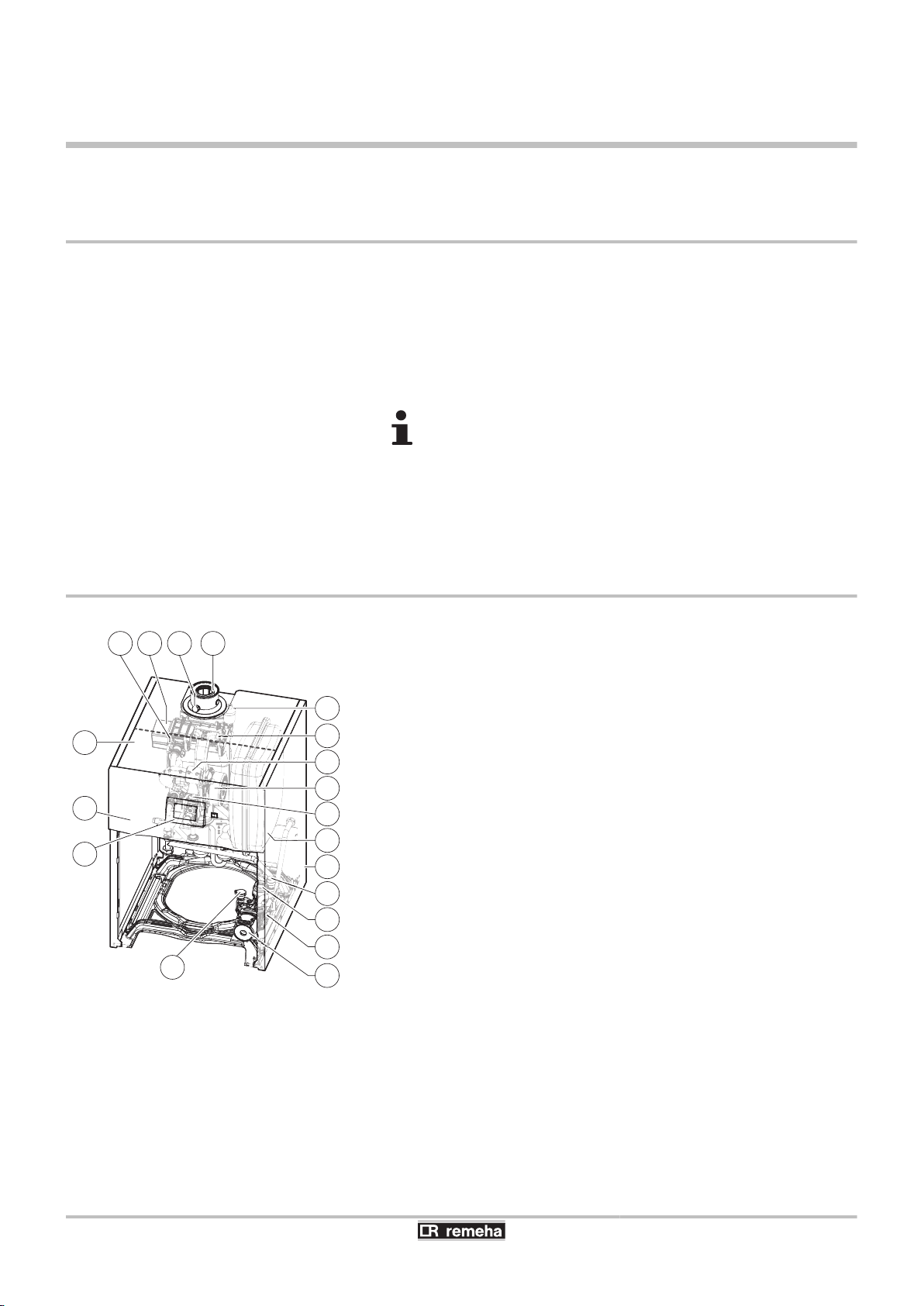
4.2 Main parts
1
2
3
4
5
6
7
8
9
10
11
12
13
14
15
16
17
18
19
Flue gas discharge pipe
Flue gas measuring point
Heat exchanger
Ignition/ionization electrode
Box for the control PCBs
Control panel
Command module
Water pressure sensor
Circulation pump
Hydroblock
3-way valve
Safety valve
Casing
Expansion vessel
Combined venturi and gas valve unit
Fan
Air intake silencer
Mixer pipe
Automatic air vent
22/04/2016 - 300026141-001-07
13
C003073-C
1
2
8
9
7
3 4 5 6
M002513-F
1
2
8
9
7
3
10
12
13
14
4
5
6
11
19
4. Technical description CALORA TOWER GAS 15S EX CALORA TOWER GAS 25S EX
CALORA TOWER GAS 35S EX
4.3 Operating principle
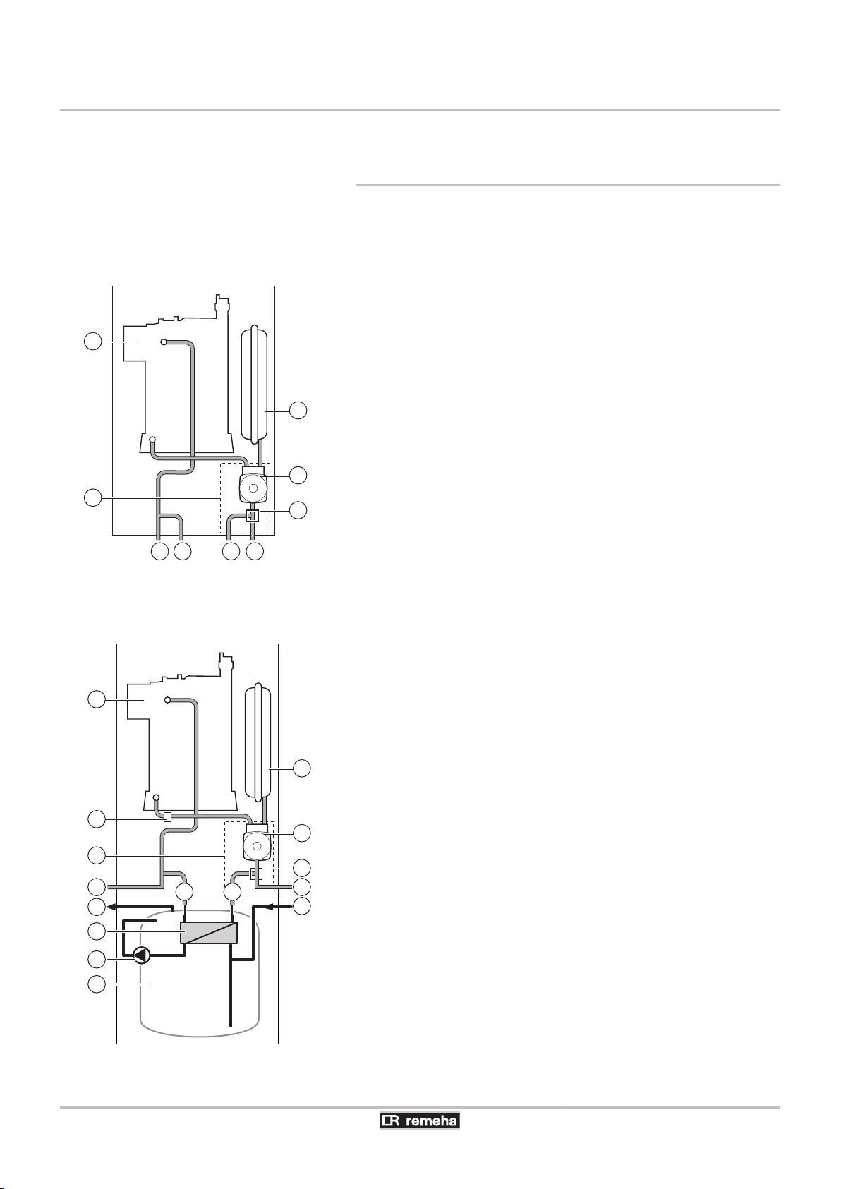
4.3.1. Skeleton Diagrams
Boiler self-standing
n
1
2
3
4
5
6
7
8
9
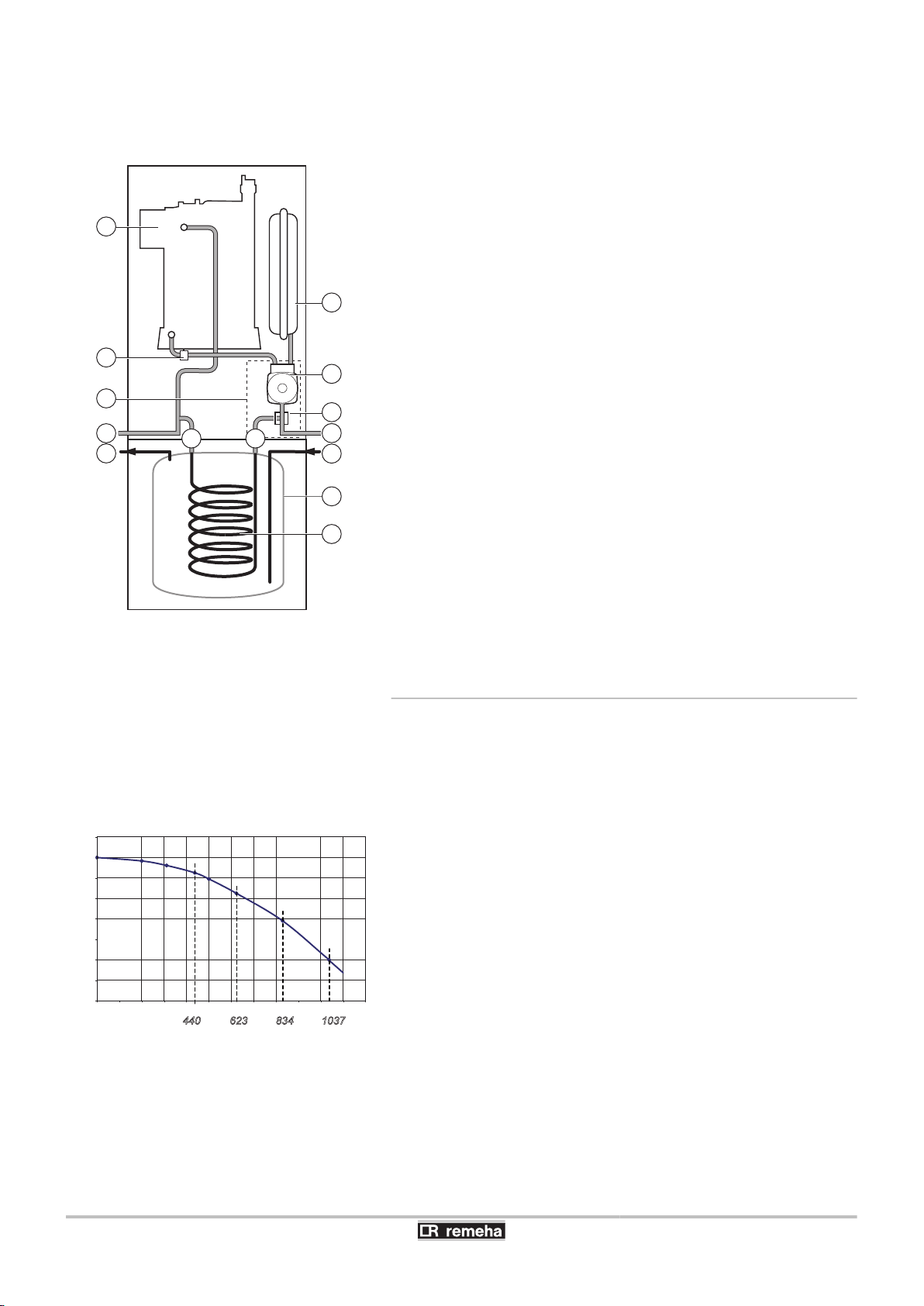
Boiler with 100HL / 220SHL type domestic hot water
n
Heat exchanger
Hydroblock
Heating flow
Primary DHW tank flow
Primary DHW tank return
Heating return
3-way valve
Circulation pump
Expansion vessel
tank
1
2
3
Heat exchanger
Hydroblock
Heating flow
4
5
6
7
8
9
10
11
12
14
13
14
19
Plate exchanger inlet
Plate exchanger outlet
Heating return
3-way valve
Circulation pump
Expansion vessel
Domestic hot water outlet
Domestic cold water inlet
Plate heat exchanger
Domestic hot water pump
Domestic hot water tank
Safety valve
22/04/2016 - 300026141-001-07
M002514-D
1
2
8
9
7
3
15
16
17
18
4
5
6
19
H (mbar)
C003452-E
Q (l/h)
0 200 400 600 800 1000 1200
0
100
200
300
400
500
600
700
800
B
A
C
D
1037834623440
CALORA TOWER GAS 15S EX CALORA TOWER GAS 25S EX
CALORA TOWER GAS 35S EX
Boiler with 100SL / 160SL / 200SSL type domestic hot
n
water tank
4. Technical description
1
2
3
4
5
6
7
8
9
15
16
17
18
19
Heat exchanger
Hydroblock
Heating flow
Coil exchanger inlet
Coil exchanger outlet
Heating return
3-way valve
Circulation pump
Expansion vessel
Domestic hot water outlet
Domestic cold water inlet
Domestic hot water tank
Domestic water coil
Safety valve
22/04/2016 - 300026141-001-07
4.3.2. Circulation pump
Pump specifications
n
15 - 25 kW boilers
H
Q
A
B
C
D
Manometric height available for the heating circuit
Water flow
Useful output (ΔT 20 K)
10 kW
15 kW
20 kW
25 kW
15
0
0 200 400 600 800 1000 1200 1400
1465
1600
100
200
300
400
500
600
700
H (mbar)
Q (l/h)
A
L000697-A
4. Technical description CALORA TOWER GAS 15S EX CALORA TOWER GAS 25S EX
CALORA TOWER GAS 35S EX
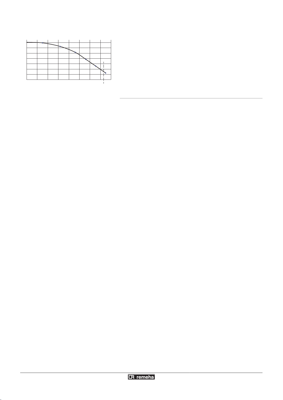
35 kW boilers
H
Q
A
Manometric height available for the heating circuit
Water flow
Useful output 35 kW (ΔT 20 K)
4.3.3. Water flow rate
The boiler’s modulating control system limits the maximum difference
in temperature between the heating flow and return and the maximum
speed at which the flow temperature increases. In this way, the boiler
does not require a minimum water flow rate.
16
22/04/2016 - 300026141-001-07
CALORA TOWER GAS 15S EX CALORA TOWER GAS 25S EX
CALORA TOWER GAS 35S EX
5 Installation
5.1 Regulations governing installation
WARNING
Installation of the appliance must be done by a qualified
engineer in accordance with prevailing local and national
regulations.
5.2 Package list
5.2.1. Standard delivery
5. Installation
The delivery includes:
4 The boiler, fitted with an earthed mains plug
4 Attachment for C-mix optional PCB
4 Sticker with details on gas type
4 Installation and Service Manual
4 User Guide
5.2.2. Accessories
Various options are available depending on the configuration of the
installation.
4 Boiler - DHW tank connection kits
4 Central connection kit - right / left
4 Mixing valve kit for integration DHW tank
4 Connection kit for external mixing valve
4 Fitting for circulating pipe
4 Flue kit
4 Flue gas adapters for concentric 80/125 mm or eccentric 80/80
mm connection
4 iSense programmable control system for modulating boiler
control (Cable on RF)
4 C-mix control PCB
4 Outside sensor
4 Flue gas temperature sensor
4 Electronic boards for extension
4 DHW expansion vessel
4 Propane conversion kit
22/04/2016 - 300026141-001-07
17
C003074-E
Auf ERDGAS H eingestellt
für DE: Erdgas E
Réglé au gaz naturel H
Geregeld voor aardgas H
Preset for natural gas H
G20 - 20 mbar
8366-4038
1 2
5. Installation CALORA TOWER GAS 15S EX CALORA TOWER GAS 25S EX
CALORA TOWER GAS 35S EX
4 Cleaning tools
5.3 Choice of the location
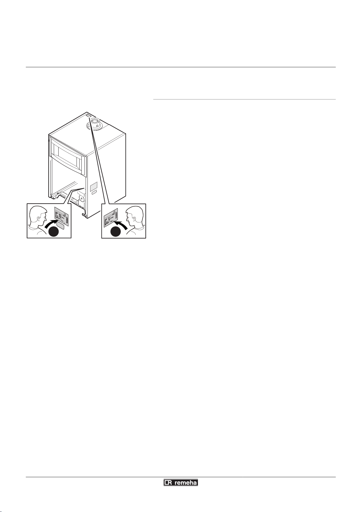
5.3.1. Type plate
The data plates provide important information on the
appliance: serial number, model, gas category, etc.
1
2
This data plate is affixed to the inside side panel of the
appliance in the factory.
When installation has been completed, affix the data plate
provided in the instructions bag to the casing of the
appliance in a position where it can be seen.
18
22/04/2016 - 300026141-001-07
C003080-F
1100
min.500
320
(1)
680
min.
250
844
500
M002515-C
1700
min.500
320
(1)
min.
250
844
500
M002516-C
1100
min.500
320
(1)
min.
250
A
500
CALORA TOWER GAS 15S EX CALORA TOWER GAS 25S EX
CALORA TOWER GAS 35S EX
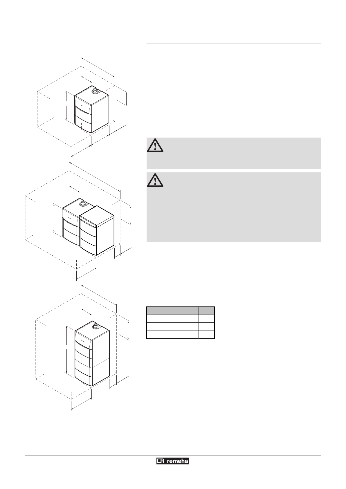
5.3.2. Positioning of the appliance
5. Installation
(1)
Minimum recommended distance
4 Before mounting the boiler, decide on the ideal position for
mounting, bearing the Directives and the dimensions of the
appliance in mind.
4 When choosing the position for mounting the boiler, bear in mind
the authorised position of the combustion gas discharge outlets
and the air intake opening.
4 To ensure adequate accessibility to the appliance and facilitate
maintenance, leave enough space around the boiler.
WARNING
It is forbidden to store inflammable products and materials
in the boiler room or close to the boiler, even temporarily.
CAUTION
4 The boiler must be installed in a frost-free
environment.
4 An earthed electrical connection must be available
close to the boiler.
4 A connection to the mains drainage system for the
discharge of condensate must be available close to
the boiler.
22/04/2016 - 300026141-001-07
(1)
Minimum recommended distance
DHW calorifier type A
100 HL 1408
160 SL 1688
220 SHL 1968
19
C003075-E
680
min. 500
600
844
320
(1)
500
(1)
500
(1)
5. Installation
CALORA TOWER GAS 15S EX CALORA TOWER GAS 25S EX
CALORA TOWER GAS 35S EX
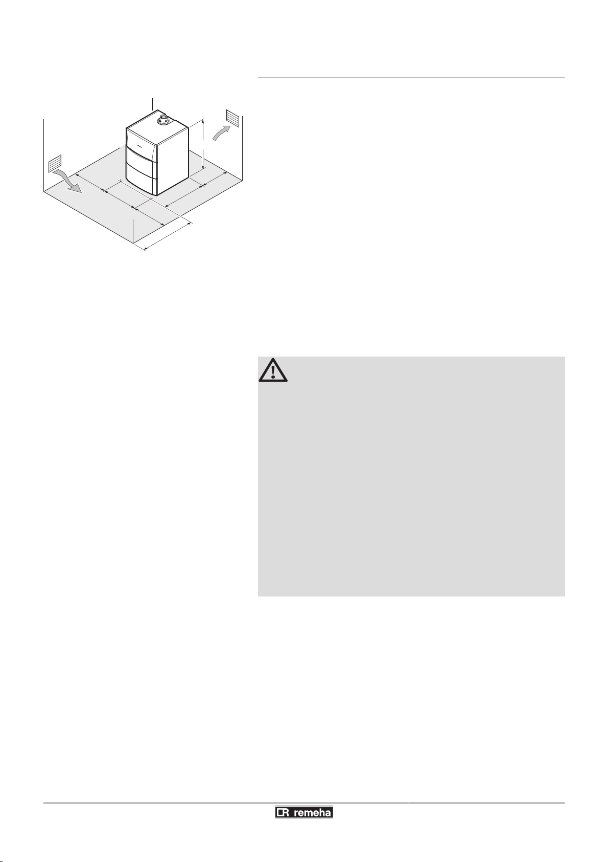
5.3.3. Ventilation
(1)
Connection to a chimney
n
Minimum recommended distance
Do not obstruct the air inlets in the room (even partially).
The compulsory cross section of aeration vents in the premises in
which the boiler is installed must comply with the standards current
in the country.
CAUTION
In order to avoid damage to the boiler, it is necessary to
prevent the contamination of combustion air by chlorine
and/or fluoride compounds, which are particularly
corrosive. These compounds are present, for example, in
aerosol sprays, paints, solvents, cleaning products,
washing products, detergents, glues, snow clearing salts,
etc. Therefore:
20
4 Do not pull in air evacuated from premises using such
products: hairdressing salons, dry cleaners,
industrial premises (solvents), premises containing
refrigeration systems (risk of refrigerant leakage),
etc.
4 Do not stock such products close to the boilers.
If the boiler and/or peripheral equipment are corroded
by such chloride or fluoride compounds, the
contractual guarantee cannot be applied.
Forced flue connection
n
If the discharge of combustion gases and the intake of combustive air
are done using a concentric flue, ventilation of the boiler room is only
necessary if a mechanical connector is fitted to the gas supply (as per
the description in the DTU 61.1 standard).
22/04/2016 - 300026141-001-07
C003076-C
600
520 436
844
918
240
74
251
105,5
128,5
70
57
55
55
55
112
150
254
680
132
1
5
6
7
8
2
3
4
121,5
(1)
16
61
CALORA TOWER GAS 15S EX CALORA TOWER GAS 25S EX
CALORA TOWER GAS 35S EX
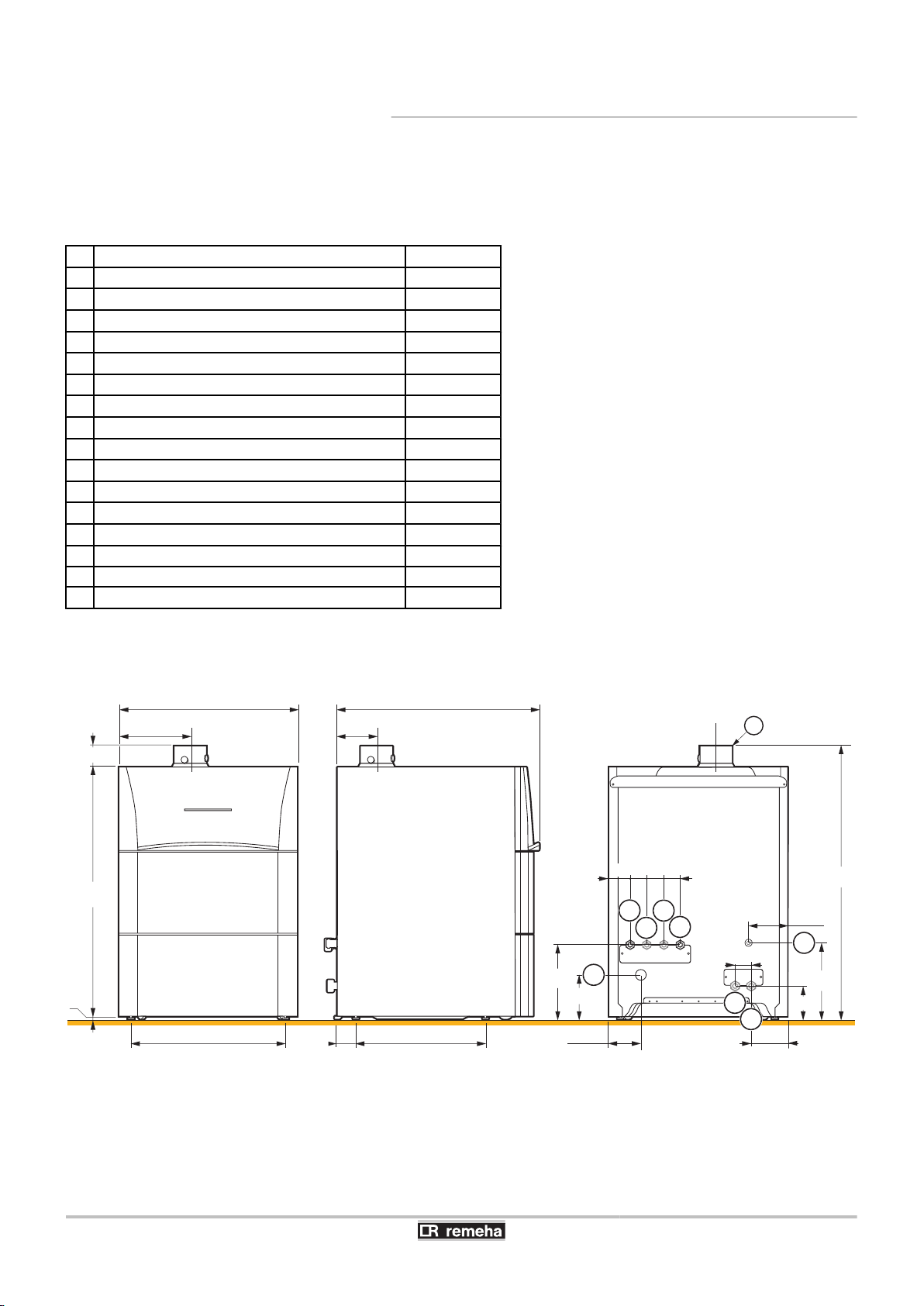
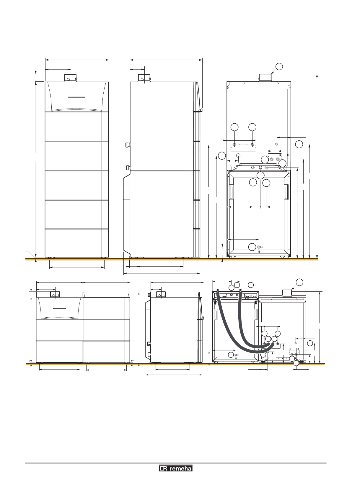
5.3.4. Main dimensions
Key
n
Direct heating circuit return G¾"
A
Direct heating circuit flow G¾"
Z
Gas supply G1/2"
E
Condensates discharge - PVC pipe Ø 24x19 mm
R
Primary return independent DHW tank - (Option) G¾"
T
Primary flow independent DHW tank - (Option) G¾"
Y
Heating flow circuit with mixing valve - (Option) G¾"
U
Heating return circuit with mixing valve - (Option) G¾"
I
Domestic cold water inlet G¾"
P
Domestic hot water outlet G¾"
a
DHW circulation loop return - Pipe G¾"
z
DHW drain valve (on the front of the DHW tank) ext. Ø 14 mm
e
Primary solar coil inlet ext. Ø 18 mm
r
Primary solar coil outlet ext. Ø 18 mm
t
Air/flue gas connection Ø 80/125 mm
y
(1) Adjustable feet 0 to 20 mm
5. Installation
Boiler only
n
22/04/2016 - 300026141-001-07
21
M002517-B
1408
520
723
70
55
245 70
167
816
715
4
1482
598
818
3
680
132
600
240
74
105,5
87
300
128,5
40
121,5
680
(2)
1 2
7
8
11
10
13
12
436
16
61
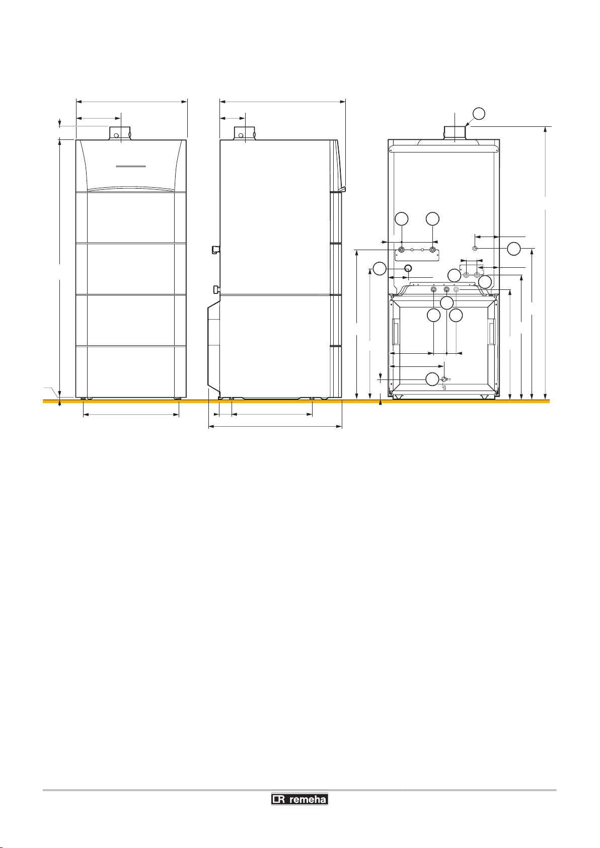
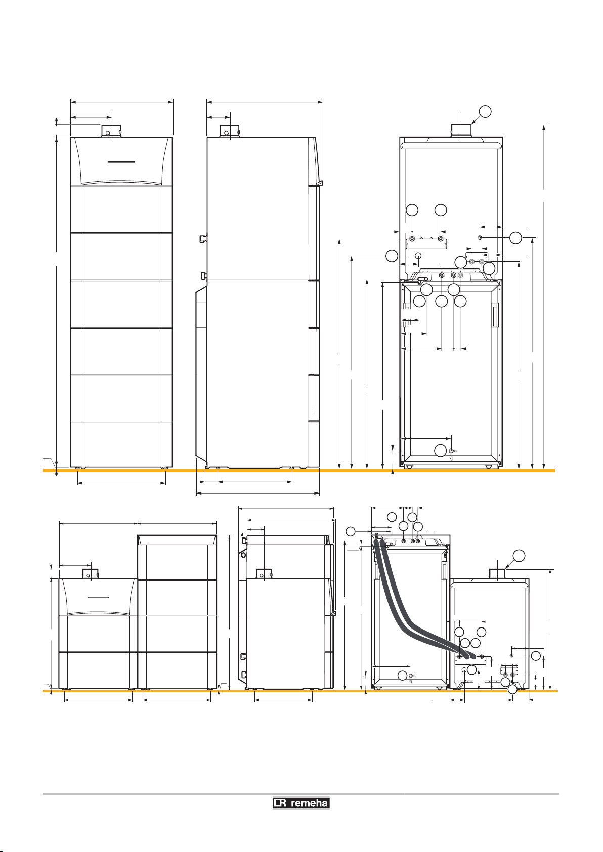
5. Installation CALORA TOWER GAS 15S EX CALORA TOWER GAS 25S EX
CALORA TOWER GAS 35S EX
Boiler with 100HL type domestic hot water tank
n
22
22/04/2016 - 300026141-001-07
M002518-B
520
723
70
55
245 70
40
167
4
3
680
132
600
240
74
105,5
87
300
128,5
121,5
(2)
1 2
7
8
11
10
13
436
12
1688
1762
1098
1096
994
956
880
16
61
M002519-D
245 70
10
11
12
520
723
87
300
(2)
13
600 600
520 436
844
917,5
240
74
920
251
105,5
128,5
70
55
167
112
150
254
680
132
1
5
6
7
8
2
3
121,5
(1)
4
16
CALORA TOWER GAS 15S EX CALORA TOWER GAS 25S EX
CALORA TOWER GAS 35S EX
Boiler with 160SL type domestic hot water tank
n
5. Installation
22/04/2016 - 300026141-001-07
23
M002520-B
520
723
70
55
245 70
167
4
3
680
132
600
240
74
105,5
88
300
128,5
121,5
(2)
1 2
7
8
11
10
13
16
43661
1378
1375
1274
1160
1116
1236
40
12
157
115
1968
2042
14
15
M002521-C
(2)
600 600
520 520 436
844 1201
918
240
74
251
1116
1160
18,5
105,5
128,5
55
112
150
254
680
723
132
7
8
3
4
121,5
(1)
70
167
1
2
245
157
115
70
40
88
300
13
11
10
12
14
15
5
6
16
5. Installation CALORA TOWER GAS 15S EX CALORA TOWER GAS 25S EX
CALORA TOWER GAS 35S EX
Boiler with 220SHL type domestic hot water tank
n
24
22/04/2016 - 300026141-001-07
C003109-B
1
2
notice
handleiding
C003110-C
4
3
CALORA TOWER GAS 15S EX CALORA TOWER GAS 25S EX
CALORA TOWER GAS 35S EX
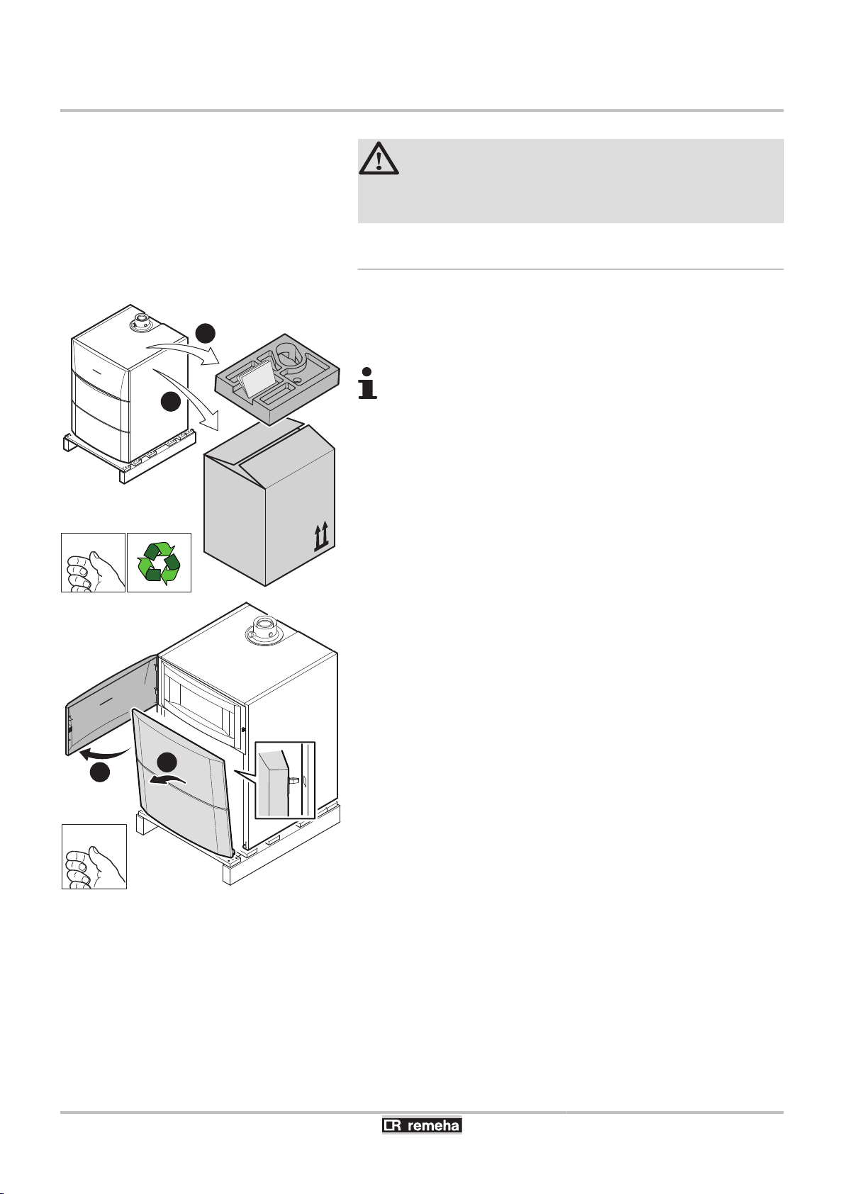
5.4 Positioning the appliance
5.4.1. Positioning the boiler on its own
1. Remove the packaging from the boiler but leave the shipping pallet
in place.
2. Remove the protective packaging.
5. Installation
CAUTION
4 Have 2 people available.
4 Handle the appliance with gloves.
The technical documentation is housed in the protective
block.
3. Open the access door on the control panel.
4. Remove the front panel by pulling firmly from both sides.
5. Remove the front panel.
22/04/2016 - 300026141-001-07
25
C003111-D
5
5
C003217-C
6
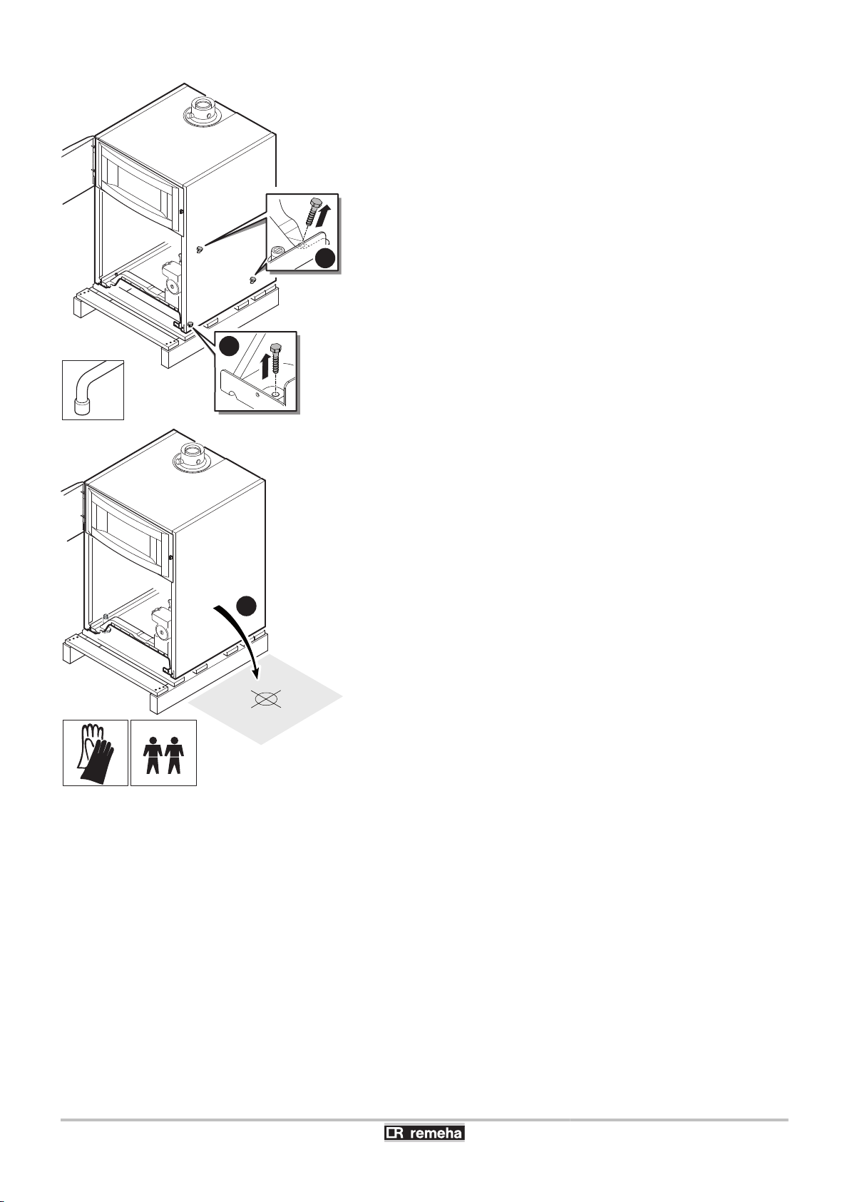
5. Installation CALORA TOWER GAS 15S EX CALORA TOWER GAS 25S EX
CALORA TOWER GAS 35S EX
6. Remove the retaining screws.
7. Lift the boiler and position it on the ground
26
22/04/2016 - 300026141-001-07
C003078-C
(1)
7
M002522-B
4
3
CALORA TOWER GAS 15S EX CALORA TOWER GAS 25S EX
CALORA TOWER GAS 35S EX
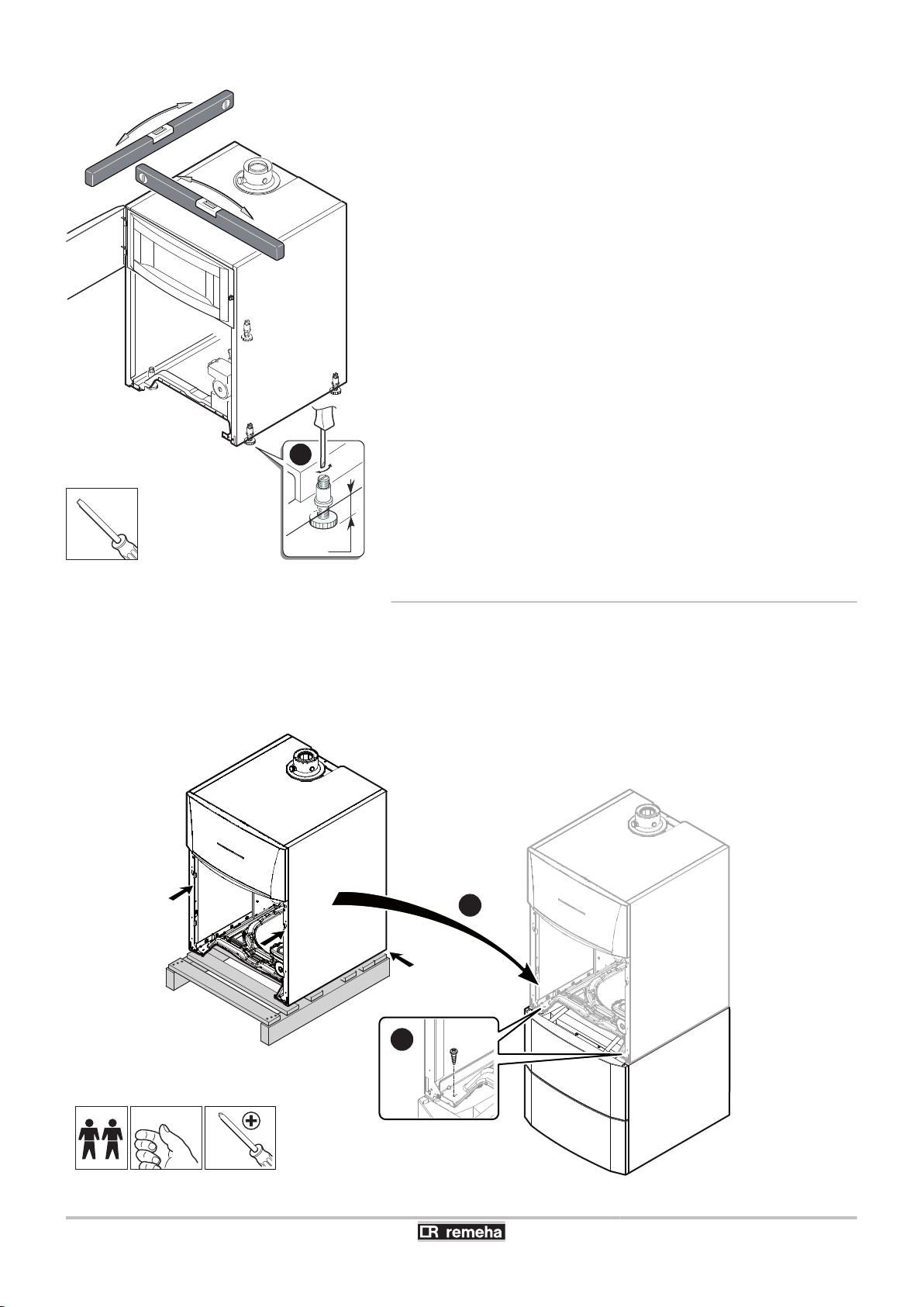
8. Level the appliance using the adjustable feet.
(1) Adjustment range: 0 to 20 mm
9. Slot the bottom of the front panel into the notches on the front of
the appliance.
10.Lift the panel and push the clips down firmly into the notches on
top of the appliance.
5. Installation
5.4.2. Fitting the boiler to a DHW tank
1. Put the DHW tank in place.
Refer to the DHW tank’s installation, use and maintenance
¼
instructions.
2. Carry out steps 1 to 6 described above.
See chapter "Positioning the boiler on its own", page 25
¼
3.
22/04/2016 - 300026141-001-07
Position the boiler on the DHW tank.
27

5. Installation CALORA TOWER GAS 15S EX CALORA TOWER GAS 25S EX
CALORA TOWER GAS 35S EX
4. Put the 2 screws in place at the front to attach the boiler to the
DHW tank.
5.4.3. Positioning the boiler to the left or right of
a DHW tank
1. Put the DHW tank in place.
Refer to the DHW tank’s installation, use and maintenance
¼
instructions.
2. Position the boiler beside the DHW tank.
See chapter "Positioning the boiler on its own", page 25
¼
5.5 Hydraulic connections
5.5.1. Flushing the system
Fitting the appliance to new installations
n
4 Clean the installation with a universal cleaner to eliminate debris
from the system (copper, hemp, flux).
4 Thoroughly flush the installation until the water runs clear and
shows no impurities.
Fitting the appliance to existing installations
n
4 Remove sludge from the installation.
4 Flush the installation.
4 Clean the installation with a universal cleaner to eliminate debris
from the system (copper, hemp, flux).
4 Thoroughly flush the installation until the water runs clear and
shows no impurities.
28
22/04/2016 - 300026141-001-07
 Loading...