

REMEHA Calenta 25s, Calenta 40c, Calenta 28c, Calenta 35s Installation And Service Manual
High-efficiency wall-hung condensing gas boilers
Calenta 25s - 28c - 35s - 40c
Netherlands
EN
Installation and
Service Manual
7600585-01

EG declaration of conformity
The device complies with the standard type described in the EG
declaration of conformity. It was manufactured and commissioned in
accordance with European directives.
The original of the declaration of compliance is available from the
manufacturer.

Contents
1 Introduction ................................................................................................6
1.1 Symbols used .......................................................6
1.2 Abbreviations ........................................................6
1.3 General ..................................................................6
1.3.1 Manufacturer's liability .............................................6
1.3.2 Installer's liability .....................................................7
1.4 Homologations ......................................................7
1.4.1 Certifications ...........................................................7
1.4.2 Equipment categories .............................................9
1.4.3 Additional Directives ................................................9
1.4.4 Factory test .............................................................9
2 Safety instructions and recommendations ............................................10
2.1 Safety instructions .............................................10
2.2 Recommendations ..............................................10
3 Technical description ..............................................................................12
3.1 General description ............................................12
3.2 Main parts ............................................................12
3.3 Operating principle .............................................13
3.3.1 Gas/air setting .......................................................13
3.3.2 Combustion ...........................................................14
3.3.3 Heating and domestic hot water production ..........14
3.3.4 Control system ......................................................14
3.3.5 Adjustment ............................................................14
3.3.6 Regulation of the water temperature .....................15
3.3.7 Protection against a shortage of water ..................15
3.3.8 Maximum temperature protection .........................15
3.3.9 Skeleton Diagrams ................................................16
3.3.10 Shunt pump ...........................................................16
3.3.11 Water flow rate ......................................................17
3.4 Technical specifications ....................................17
4 Installation ................................................................................................20
4.1 Regulations governing installation ...................20
4.2 Package list .........................................................20
4.2.1 Standard delivery ..................................................20
4.2.2 Accessories ...........................................................21
040412 - 7600585-01
1

Contents
4.3 Choice of the location ........................................22
4.3.1 Data plate ..............................................................22
4.3.2 Location of the boiler .............................................22
4.3.3 Ventilation .............................................................23
4.3.4 Main dimensions ...................................................24
4.4 Positioning the boiler .........................................25
4.5 Alternatives for hydraulic connections ............26
4.5.1 Connection of the underfloor heating ....................26
4.5.2 Connection of a solar hot water tank .....................26
4.5.3 Connection of an independent hot water
tank .......................................................................27
4.5.4 Geyser use ............................................................28
4.5.5 Solo use ................................................................29
4.6 Hydraulic connections .......................................29
4.6.1 Flushing the system ..............................................29
4.6.2 Connection of the heating circuit ...........................30
4.6.3 Hydraulic connection of the water circuit for domestic
use ........................................................................31
4.6.4 Connecting the expansion vessel .........................31
4.6.5 Connecting the condensate discharge pipe ..........31
4.7 Gas connection ...................................................32
4.8 Connections for the air and exhaust
pipes ....................................................................32
4.8.1 Classification .........................................................32
4.8.2 Outlets ...................................................................33
4.8.3 Lengths of the air/flue gas pipes ...........................34
4.8.4 Specific air/flue gas applications ...........................36
4.8.5 Additional Directives ..............................................36
4.8.6 Air/Exhaust adapter ...............................................37
4.8.7 Connection of the combustion gas exhaust
pipe .......................................................................38
4.8.8 Connection of the air intake pipe ...........................38
4.9 Electrical connections ........................................39
4.9.1 Control unit ............................................................39
4.9.2 Recommendations ................................................40
4.9.3 Standard control PCB ...........................................41
4.9.4 Connecting the room thermostat ...........................42
4.9.5 Connecting the outside temperature sensor ........43
4.9.6 Connect frost protection ........................................43
4.9.7 Connecting the calorifier sensor/thermostat .........44
4.9.8 PC/Laptop connection ...........................................45
4.9.9 Shutdown input .....................................................45
4.9.10 Release input ........................................................45
040412 - 7600585-01
4.10 Optional electrical connections ........................46
4.10.1 Connection options for the 0-10 V control PCB
(IF-01) ...................................................................46
4.10.2 Connection possibilities for the PCB (SCU-
S02) .......................................................................47
2

4.11 Electrical diagram ...............................................50
4.12 Filling the system ...............................................51
4.12.1 Water treatment ....................................................51
4.12.2 Filling the siphon ...................................................51
4.12.3 Filling the system ..................................................52
5 Commissioning ........................................................................................53
5.1 Control panel .......................................................53
5.1.1 Functions of the keys ............................................53
5.1.2 Meaning of the symbols on the display .................53
5.2 Check points before commissioning ................54
5.2.1 Preparing the boiler for commissioning .................54
5.2.2 Gas circuit .............................................................55
5.2.3 Hydraulic circuit .....................................................55
5.2.4 Electrical connections ...........................................55
5.3 Commissioning the boiler ..................................55
5.4 Gas settings ........................................................57
5.4.1 Adapting to another gas type ................................57
5.4.2 Setting the air/gas ratio (Full load) ........................57
5.4.3 Setting the air/gas ratio (Part load) ......................59
5.4.4 Basic setting for the gas/air ratio ...........................60
5.5 Checks and adjustments after
commissioning ...................................................60
5.5.1 Finalizing work ......................................................60
5.6 Reading out measured values ...........................61
5.6.1 Reading the various current values .......................61
5.6.2 Readout from the hour counter and percentage of
successful starts ....................................................62
5.6.3 Status and sub-status ...........................................63
5.7 Changing the settings ........................................64
5.7.1 Parameter descriptions .........................................64
5.7.2 Modification of the user-level parameters .............66
5.7.3 Modification of the installer-level parameters ........67
5.7.4 Setting the maximum heat input for central heating
operation ...............................................................68
5.7.5 Return to the factory settings ................................69
5.7.6 Carrying out an auto-detect ...................................70
5.7.7 Setting the manual mode ......................................70
5.7.8 Setting the legionella protection function ..............70
040412 - 7600585-01
3

Contents
6 Switching off the boiler ............................................................................71
6.1 Installation shutdown .........................................71
6.2 Frost protection ..................................................71
6.3 Switching off the central heating ......................72
6.4 Shutting down domestic hot water
production ...........................................................72
7 Checking and maintenance .....................................................................73
7.1 Maintenance message ........................................73
7.2 Preventive maintenance with automated service
message ..............................................................73
7.2.1 Resetting the automatic maintenance
message ................................................................74
7.2.2 Dealing with the next maintenance message and
starting the new maintenance period ....................74
7.3 Standard inspection and maintenance
operations ...........................................................75
7.3.1 Checking the hydraulic pressure ...........................75
7.3.2 Checking the ionization current .............................75
7.3.3 Checking the transfer capacity ..............................75
7.3.4 Checking the tightness of the flue gas evacuation and
air inlet connections ..............................................76
7.3.5 Checking combustion ............................................76
7.3.6 Checking the automatic air vent ............................77
7.3.7 Checking the safety valve .....................................77
7.3.8 Checking the siphon ..............................................77
7.3.9 Checking the burner and cleaning the heat
exchanger .............................................................78
7.4 Specific maintenance operations ......................79
7.4.1 Replacing the ionization/ignition electrode ............79
7.4.2 Cleaning the plate exchanger (domestic hot water
end) and the water filter cartridge .........................79
7.4.3 Replacing the 3-way valve ....................................82
7.4.4 Replacing the non-return valve .............................83
7.4.5 Assembling the boiler ............................................84
8 Troubleshooting .......................................................................................85
040412 - 7600585-01
8.1 Error codes ..........................................................85
8.2 Shutdowns and lock-outs ..................................88
8.2.1 Blockage ...............................................................88
8.2.2 Blocking .................................................................88
8.3 Error memory ......................................................90
8.3.1 Error readout memorised ......................................91
8.3.2 Deletion of the error display ..................................92
4

9 Spare parts ................................................................................................93
9.1 General ................................................................93
9.2 Spare parts ..........................................................93
040412 - 7600585-01
5

1. Introduction
1 Introduction
1.1 Symbols used
Calenta 25s - 28c - 35s - 40c
In these instructions, various danger levels are employed to draw the
user's attention to particular information. In so doing, we wish to
safeguard the user's safety, obviate hazards and guarantee correct
operation of the appliance.
DANGER
Risk of a dangerous situation causing serious physical
injury.
WARNING
Risk of a dangerous situation causing slight physical
injury.
1.2 Abbreviations
1.3 General
CAUTION
Risk of material damage.
Signals important information.
¼ Signals a referral to other instructions or other pages in the
instructions.
4 3CE: Collective conduit for sealed boiler
4 Central heating: Central heating
4 COP: Energy performance
4 DHW: Domestic hot water
4 HRU: Heat Recovery Unit
1.3.1. Manufacturer's liability
Our products are manufactured in compliance with the requirements
of the various applicable European Directives. They are therefore
delivered with [ marking and all relevant documentation.
6
040412 - 7600585-01
Calenta 25s - 28c - 35s - 40c
1. Introduction
In the interest of customers, we are continuously endeavouring to
make improvements in product quality. All the specifications stated in
this document are therefore subject to change without notice.
Our liability as the manufacturer may not be invoked in the following
cases:
4 Failure to abide by the instructions on using the appliance.
4 Faulty or insufficient maintenance of the appliance.
4 Failure to abide by the instructions on installing the appliance.
1.3.2. Installer's liability
The installer is responsible for the installation and inital start up of the
appliance. The installer must respect the following instructions:
4 Read and follow the instructions given in the manuals provided
with the appliance.
4 Carry out installation in compliance with the prevailing legislation
and standards.
4 Perform the initial start up and carry out any checks necessary.
4 Explain the installation to the user.
4 If a maintenance is necessary, warn the user of the obligation to
check the appliance and maintain it in good working order.
4 Give all the instruction manuals to the user.
1.4 Homologations
1.4.1. Certifications
CE identification no
NOx classification
Type of connection
(Flue gas outlet)
Depending on the type of appliance and the gross heat
requirements for domestic water in accordance with NEN
5128, efficiency values up to 0,825 can be applied to
determine EPC.
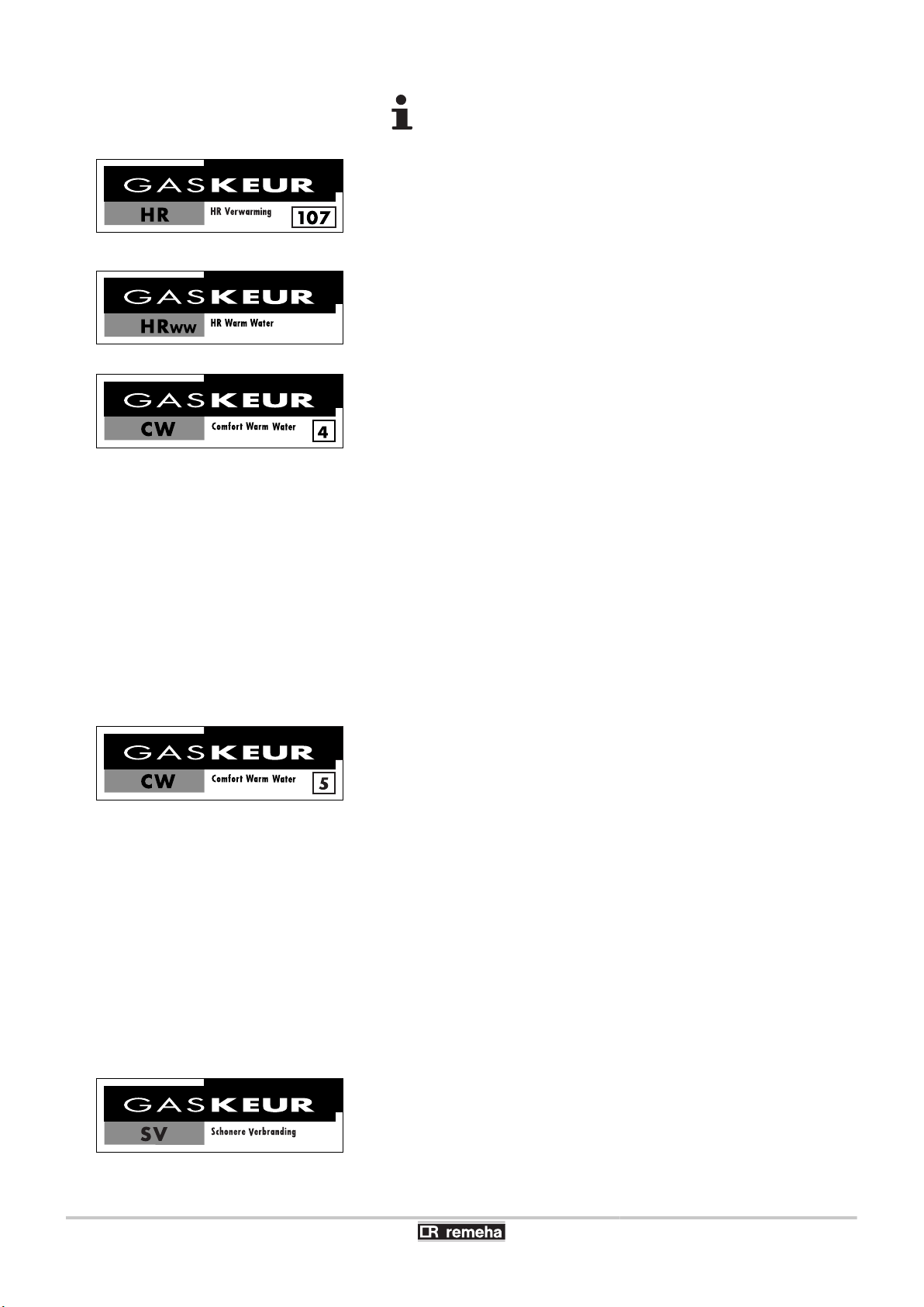
Approval labels for gas
n
The boiler has been given several approval labels for gas. Stichting
Energie Prestatiekeur grants these independent labels on
performance to gas consumption appliances that meet specific
provisions on a certain number of aspects (efficiency, environmental
friendliness, comfort). The labels have the following meaning:
PIN 0063BT3444
5 (EN 297 pr A3, EN 656)
B23 , B
C
93
, B33 , C13 , C33 , C43 , C53 , C63 , C83 ,
23P
040412 - 7600585-01
7
T001057-A
T001058-A
T001055-A
T001795-A
T001059-A
1. Introduction
Calenta 25s - 28c - 35s - 40c
The labels are not guaranteed if the boiler is adapted to
G20 or G31.
HR 107 gas approval (High efficiency heating)
This means that the efficiency of the boiler when producing heating
water is 107% higher than the Gaskeur HR criterion in relation to
Hi. This means that the boiler is economical and therefore less costly
and more environmentally friendly.
HRww gas approval (High efficiency hot water)
This implies that the hot water/heating boiler produces hot water
economically and efficiently, without wasting energy or water
therefore.
CW 4 gas approval (Hot water comfort)
This means that, for the preparation of hot water, the Calenta 28c
satisfies application class 4. With the application of class 4, the
Calenta 28c is appropriate for:
4 A draw-off flow rate of at least 7,5 l/min at 60°C.
4 A shower function from 6 l/min up to at least 12,5 l/min at 40°C.
4 Filling a bathtub in less than 11 minutes with 120 litres of water at
40°C on average.
The simultaneity of these functions is not a requirement.
Parameters for which the performance of the Calenta 28c boiler
complies with the Hot Water Comfort classification:
4 Rotation speed on start-up 3000 rpm.
4 Maximum DHW rate 6200 rpm.
4 Energy-saving mode: Stop.
CW 5 gas approval (Hot water comfort)
This means that, for the preparation of hot water, the Calenta 40c
satisfies application class 5. With the application of class 5, the
Calenta 40c is appropriate for:
4 Hot water comfort.
4 A shower function from 6 l/min up to at least 12,5 l/min at 40°C.
4 Filling a bathtub in less than 10 minutes with 150 litres of water at
40 °C on average.
The simultaneity of these functions is not a requirement.
Parameters for which the performance of the Calenta 40c boiler
complies with the Hot Water Comfort classification:
4 Rotation speed on start-up 4000 rpm.
4 Maximum DHW rate 6800 rpm.
4 Energy-saving mode: Stop.
SV gas approval (Clean combustion)
8
040412 - 7600585-01
T001779-B
NZ
Calenta 25s - 28c - 35s - 40c
1. Introduction
This means that the boiler complies with the NOx Order and
provisions on clean combustion. The boiler has a gas/air coupling
combined with a fully premixed burner. For this reason, the emission
of NOx and CO is as low as possible.
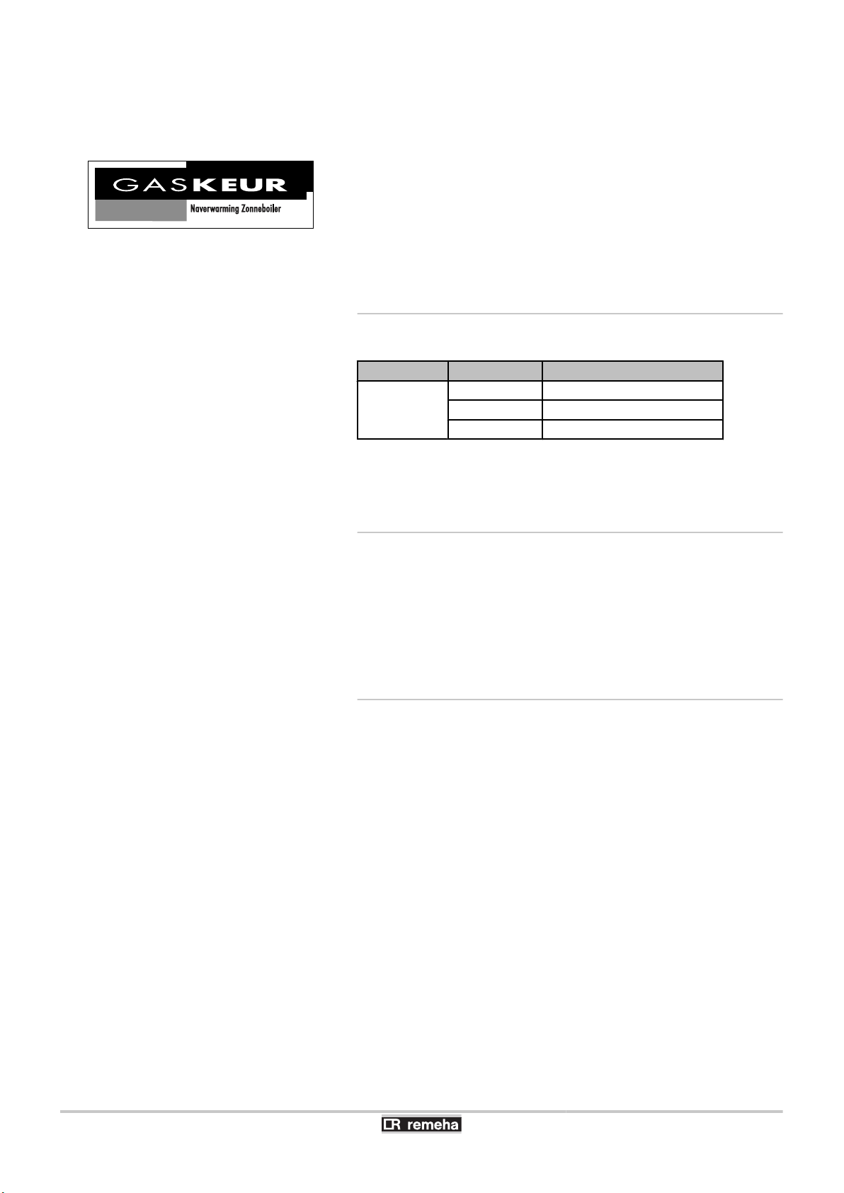
NZ gas approval (Solar water heater reheating)
This implies that the hot water/heating boiler can operate on reheating
for solar water heaters. The label (solar water heater reheating) is
valid in combination with the connection kit for solar water heaters.
Owing to the possible formation of legionella, the boiler must not be
shut down or the DHW temperature set below 60°C.
1.4.2. Equipment categories
Gas category
II
, I
2L3P
2H
Gas type Connection pressure (mbar)
G20 (Gas H) 20
G25 (Gas L) 25
G31 (Propane) 30/50
The boiler is preset in the factory to operate on natural gas G25 (Gas
L).
1.4.3. Additional Directives
Apart from the legal provisions and Directives, the additional
Directives described in these instructions must also be observed.
For all provisions and Directives referred to in these instructions, it is
agreed that all addenda or subsequent provisions will apply at the
time of installation.
1.4.4. Factory test
Before leaving the factory, each boiler is set for optimum performance
and tested to check the following items:
040412 - 7600585-01
4 Electrical safety
4 Adjustment (CO2)
4 Domestic hot water mode (Only on models with domestic hot water
production)
4 Water tightness
4 Gas tightness
4 Parameter settings
9
2. Safety instructions and recommendations
2 Safety instructions and
recommendations
2.1 Safety instructions
DANGER
If you smell gas:
1. Do not use a naked flame, do not smoke, do not
operate electrical contacts or switches ( doorbell,
light, motor, lift, etc..).
2. Shut off the gas supply.
3. Open the windows.
4. Trace possible leaks and seal them immediately.
5. If the gas leak is before the gas meter, contact the
gas supplier.
Calenta 25s - 28c - 35s - 40c
2.2 Recommendations
DANGER
If you smell flue gases:
1. Switch the appliance off.
2. Open the windows.
3. Trace possible leaks and seal them immediately.
WARNING
4 Installation and maintenance of the boiler must be
carried out by a qualified professional in compliance
with prevailing local and national regulations.
4 When working on the boiler, always disconnect the
boiler from the mains and close the main gas inlet
valve.
4 After maintenance or repair work, check all
installations to ensure that there are no leaks.
CAUTION
10
The boiler must be installed in a frost-free environment.
Keep this document close to the place where the boiler is
installed.
Casing components
040412 - 7600585-01

Calenta 25s - 28c - 35s - 40c 2. Safety instructions and recommendations
Only remove the casing for maintenance and repair operations. Put
the casing back in place after maintenance and repair operations.
Instructions stickers
The instructions and warnings affixed to the appliance must never be
removed or covered and must remain legible during the entire lifespan
of the appliance. Immediately replace damaged or illegible
instructions and warning stickers.
Modifications
Modifications may only be made to the boiler after the written
permission of Remeha to do so.
040412 - 7600585-01
11
T000822-B T000822-D
9
8
7
6
4
5
2
3
10
12
14
13
16
17
19
20
18
15
1 21
11
3. Technical description Calenta 25s - 28c - 35s - 40c
3 Technical description
3.1 General description
High-efficiency wall-hung condensing gas boilers
4 High efficiency heating.
4 Low pollutant emissions.
Boiler type:
4 Calenta 25s - 35s: Heating only (Production of domestic hot water
can be ensured by a separate hot water calorifier).
4 Calenta 28c - 40c: Heating and domestic hot water production.
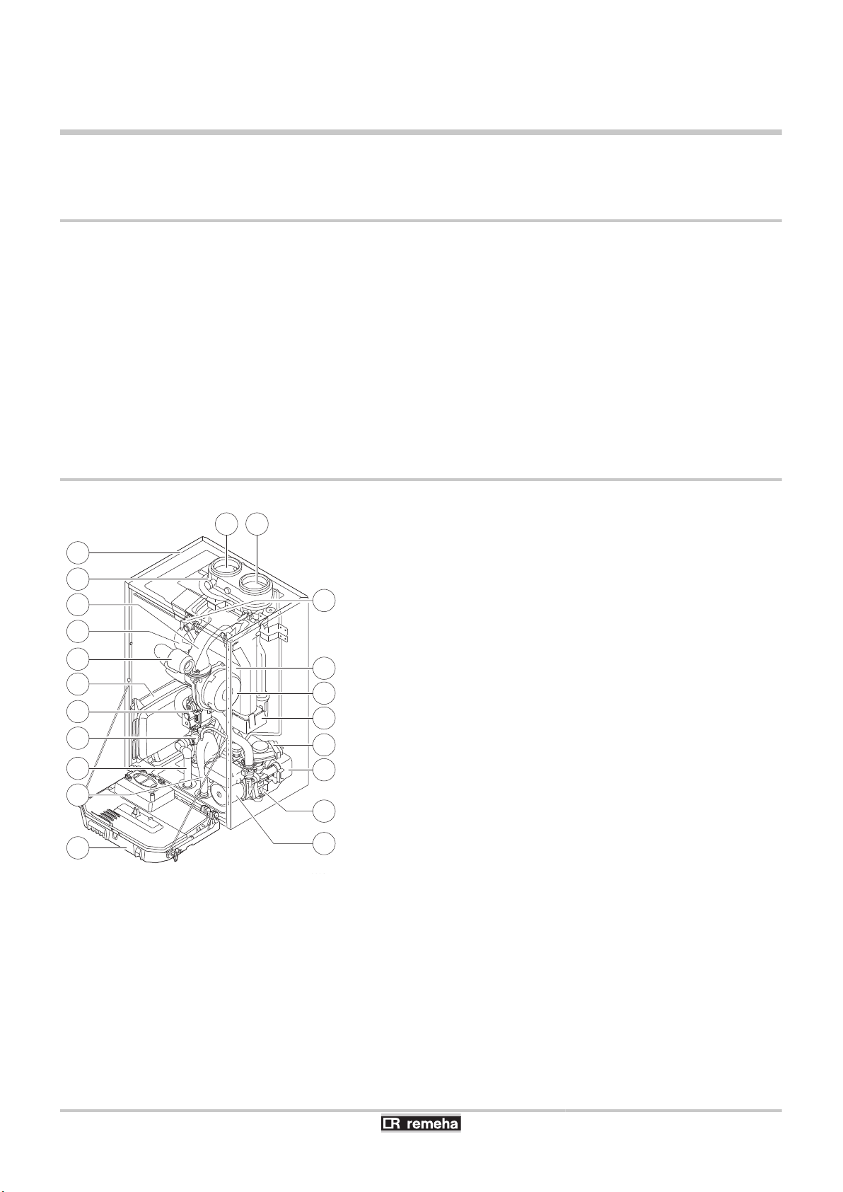
3.2 Main parts
Calenta 25s - 28c
1
2
3
4
5
6
7
8
9
10
11
12
13
14
15
Flue gas outlet
Casing/air box
Outlet for measuring combustion gases
Mixer pipe
Heating flow hose
Air intake silencer
Box for the control PCBs (accessory)
Combined venturi and gas valve unit
Flow end hydroblock
Safety valve outlet pipe
Siphon
Instrument box
Shunt pump
Return end hydroblock
Plate heat exchanger (DHW) (Only on models with
domestic hot water production)
12
16
17
18
19
20
21
3-way valve (Only on models with domestic hot water
production)
Condensate receiver tank
Fan
Heat exchanger (Central heating)
Ignition/ionization electrode
Air intake
040412 - 7600585-01
T002886-C
2
14
16
15
13
17
18
19
20
3
4
5
6
7
8
9
10
11
12
1 21
Calenta 25s - 28c - 35s - 40c
3. Technical description
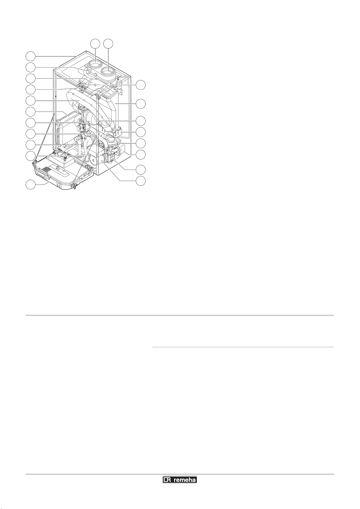
Calenta 35s - 40c
1
2
3
4
5
6
7
8
9
10
11
12
13
14
15
16
Flue gas outlet
Casing/air box
Outlet for measuring combustion gases
Mixer pipe
Heating flow hose
Air intake silencer
Box for the control PCBs (accessory)
Combined venturi and gas valve unit
Flow end hydroblock
Safety valve outlet pipe
Siphon
Instrument box
Shunt pump
Return end hydroblock
Plate heat exchanger (DHW) (Only on models with
domestic hot water production)
3-way valve (Only on models with domestic hot water
production)
3.3 Operating principle
17
18
19
20
21
Condensate receiver tank
Fan
Heat exchanger (Central heating)
Ignition/ionization electrode
Air intake
3.3.1. Gas/air setting
The casing fitted to the boiler is also used as an air box. Air is sucked
in by the fan and gas injected into the venturi by the fan intake. The
fan rotation speed is set according to the settings parameters, the
thermal energy requirement and the temperatures measured by the
temperature sensors. The gas and air are mixed in the venturi. The
gas/air ratio ensures that the quantities of gas and air are adjusted to
each other. This provides optimum combustion on the entire output
range. The gas/air mixture is fed into the burner on top of the
exchanger.
040412 - 7600585-01
13

3. Technical description
Calenta 25s - 28c - 35s - 40c
3.3.2. Combustion
The burner heats the heating water circulating in the heat
exchanger. At a return temperature lower than around 55°C, the flue
gases cool down to a temperature lower than the dew point, thus
causing the condensation of the water vapour contained in the flue
gases in the back side of the heat exchanger. The heat released
during this condensation process (the latent heat or condensing heat)
is also transferred to the heating water. The cooled combustion gases
are evacuated via the combustion gas outlet flue. The condensation
water is evacuated via a siphon.
3.3.3. Heating and domestic hot water production
On heating and domestic hot water production type boilers, an
integrated plate exchanger heats the domestic water. A 3-way valve
determines whether the heated water is fed into the heating system
or the plate exchanger. A pick-up sensor signals that a hot water tap
is being opened. This signal is transmitted to the control panel, which
then switches the 3-way valve to the hot water position and trips the
heating pump. The 3-way valve is spring-loaded but only consumes
electricity when it switches to another position.
The heating water reheats the domestic water in the plate
exchanger. In comfort mode, if there is no hot water draw-off, the
boiler handles the periodic reheating of the plate exchanger. Any
limescale particles are kept out of the plate exchanger by a selfcleaning water filter (self-cleans once every 76 hours).
3.3.4. Control system
The boiler command, called Comfort Master©, handles a reliable
heat supply. This means that the boiler treats external negative
influences in a practical manner (notably when the water-flow is
insufficient or there are problems with air supply). In the presence of
such influences, the boiler doesn't switch into locking mode, but first
reduces his power and, depending on the nature of the
circumstances, will be temporarily out of service (blocking or stop).
The boiler will continue to supply heat as long as the situation does
not become dangerous.
3.3.5. Adjustment
The power of the boiler can be adjusted in the following ways:
14
4 On/Off setting
The output between the minimum and maximum values varies
based on the heating flow set point temperature.
4 Adjustable control
The output between the minimum and maximum values varies
based on the heating flow temperature determined by the
modulating control system.
4 Analogue setting (0-10 V)
040412 - 7600585-01
T003757-A
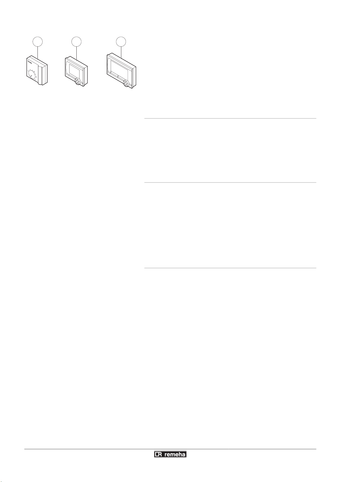
1 2 3
Calenta 25s - 28c - 35s - 40c 3. Technical description
1
2
3
Celcia 10
qSense
iSense
It is possible to connect a 2-wire on/off thermostat to the boiler such
as the Celcia 10 or a power stealing thermostat. The boiler output
can be modulated by an OpenTherm system with an appropriate
modulating thermostat such as the qSense or the iSense.
3.3.6. Regulation of the water temperature
The boiler is fitted with an electronic temperature regulator having an
outlet and return temperature probe. The flow temperature can be set
between 20°C and 90°C. The boiler reduces its power when the set
outlet-temperature is attained. The cutout temperature is the set
heating outlet-temperature + 5 °C.
3.3.7. Protection against a shortage of water
The boiler is fitted with a safety device to prevent the shortage of water
based on temperature measurements. By reducing its output when
the water flow rate is in danger of becoming insufficient, the boiler
continues to operate as long as possible. If the flow rate is too weak
ΔT ≥ 50°C or the heating flow temperature increases too much, the
boiler is locked for 10 minutes, code 5t[09. When there is no
water in the boiler or the pump is not running, the boiler goes into
safety shutdown, code e[10 at ΔT ≥ 70°C.
3.3.8. Maximum temperature protection
The overheating safety device locks the boiler when the water
temperature is too high (110°C), code e[12.
¼ For more detailed information, see chapter: "Error codes",
page 85
040412 - 7600585-01
15
R000124-A
1
4
2 3
T001874-A
1
2
3
9
8
4 5 6 7
T002537-B
0 200 400 600 800 1000 1200
Q (l/h)
10 kW
15 kW
20 kW
25 kW
615
545
435
295
437 623 830 1037
0
100
200
300
400
500
700
H (mbar)
600
3. Technical description Calenta 25s - 28c - 35s - 40c
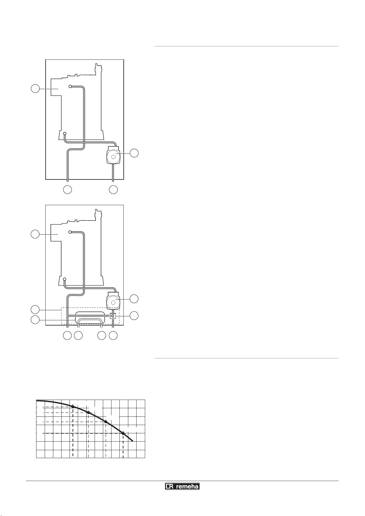
3.3.9. Skeleton Diagrams
Calenta 25s - 35s
1
2
3
4
Heat exchanger (Central heating)
Heating flow
Heating return
Shunt pump (Central heating)
Calenta 28c - 40c
1
2
3
4
Heat exchanger (Central heating)
Hydroblock
Plate heat exchanger (DHW)
Heating flow
16
5
6
7
8
9
Domestic hot water outlet
Domestic cold water inlet
Heating return
3-way valve
Shunt pump (Central heating)
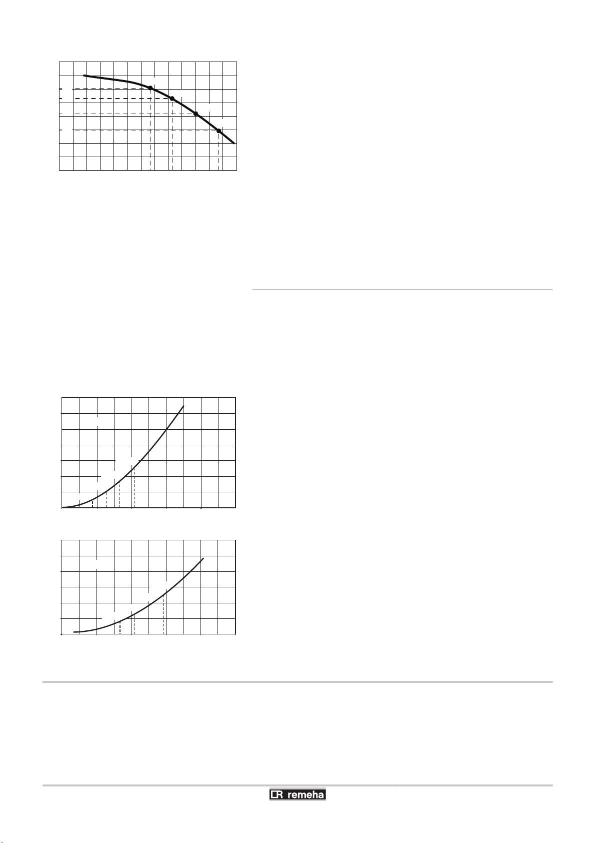
3.3.10. Shunt pump
The boiler is equipped with a circulating pump. This energy-efficient,
modulating circulating pump is controlled by the control unit based on
ΔT. The graph shows the manometric height at various outputs.
Calenta 25s - 28c
H
Q
Manometric height central heating circuit
Water flow
040412 - 7600585-01
T001748-B
0 250 500 750 1000 1250
0
100
200
300
400
500
700
800
H (mbar)
Q (l/h)
600
20 kW
25 kW
30 kW
35 kW
835 1252 1038
1465
606
418
530
291
T001978-A
0
100
200
300
400
500
600
700
0 500
1037437
15001000 2000 2500
∆p [mbar]
Q [l/h]
623 830
∆T = 20K
10 kW
15 kW
20 kW
25 kW
T001749-B
0
100
200
300
400
500
600
0 500
1043 1252 1465835
15001000 2000 2500
∆p [mbar]
Q [l/h]
∆T = 20K
20 kW
25 kW
30 kW
35 kW
Calenta 25s - 28c - 35s - 40c
3. Technical description
Calenta 35s - 40c
H
Q
Manometric height central heating circuit
Water flow
Parameters p"8 and p"9 are used to modify the pump settings:
4 If there are audible flowing noises in the system, the maximum
pump speed must be lowered using parameter p"9 (First of all,
vent the heating system).
4 If there is insufficient flow in the radiators or if they do not warm
up completely, the minimum pump speed can be increased using
parameter p"8.
¼ See chapter: "Modification of the installer-level parameters",
page 67.
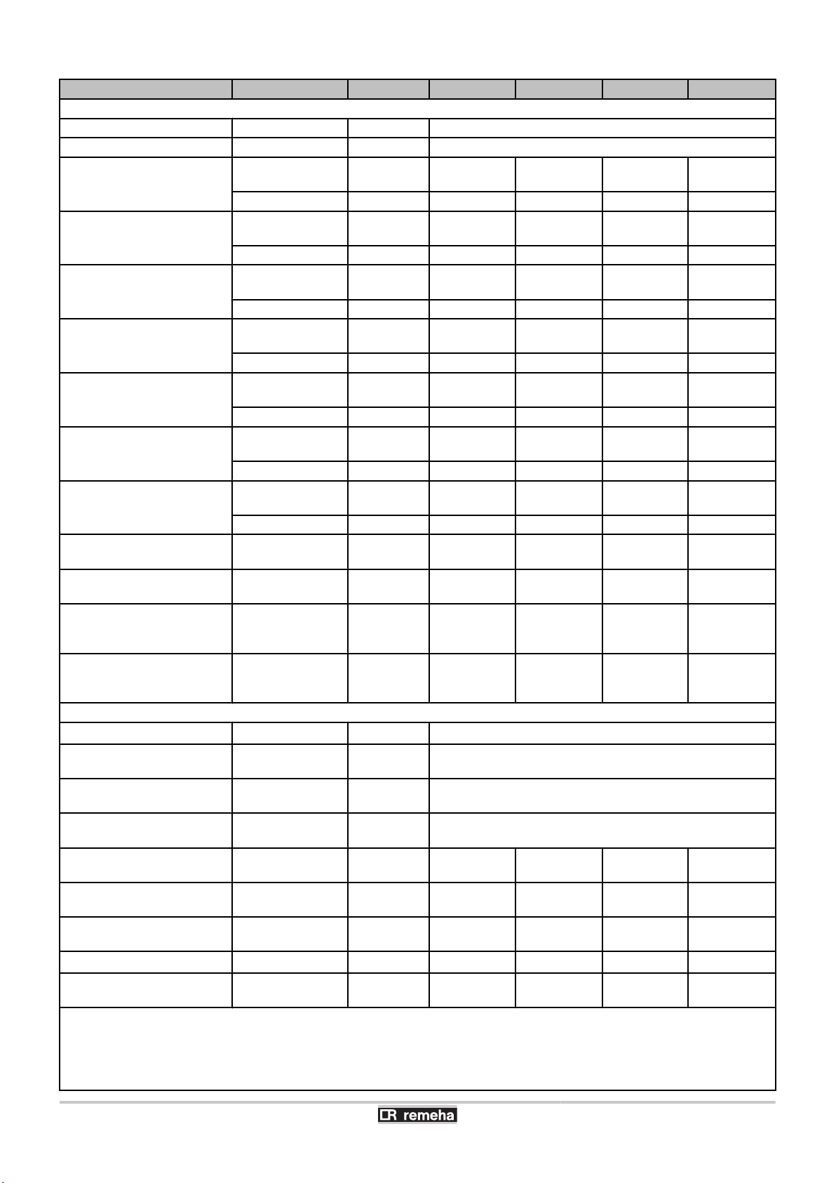
3.3.11. Water flow rate
The boiler's modulating control system limits the maximum difference
in temperature between the heating flow and return and the maximum
speed at which the flow temperature increases. In this way, the boiler
does not require a minimum water flow rate.
¼ If using thermostatic valves, see chapter: "Hydraulic
connections", page 29.
Calenta 25s
3.4 Technical specifications
040412 - 7600585-01
Δp
Q
Calenta 35s
Δp
Q
Pressure drop
Water flow (max = 1680 l/h)
Pressure drop
Water flow (max = 2460 l/h)
17
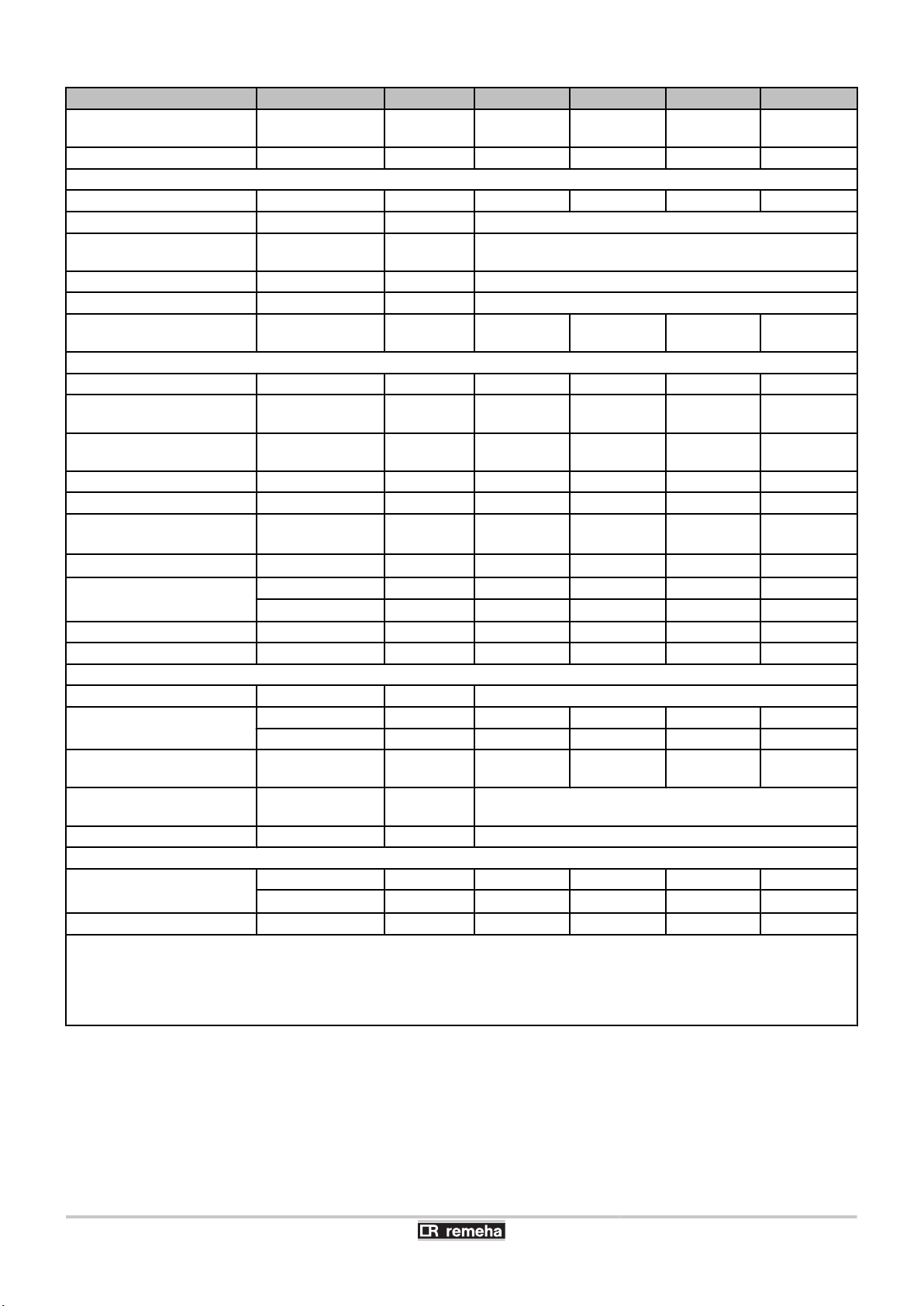
3. Technical description Calenta 25s - 28c - 35s - 40c
Boiler type Calenta
25s 28c 35s 40c
General
EC indentification no. PIN
Flow rate setting Adjustable
Nominal output (Pn)
Heating System (80/60 °C)
Nominal output (Pn)
Heating System (50/30 °C)
Nominal output (Pn)
DHW System
Nominal input (Qn)
Heating System (Hi)
Nominal input(Qn)
Heating System (Hs)
Nominal input (Qnw)
DHW System (Hi)
Nominal input (Qnw)
DHW System (Hs)
Heating efficiency under full
load (Hi) (80/60 °C)
Heating efficiency under full
load (Hi) (50/30 °C)
minimummaximum
Factory setting kW 24,1 19,4 34,0 23,3
minimummaximum
Factory setting kW 25,5 20,5 35,9 24,5
minimummaximum
Factory setting kW - 28,6 - 39,7
minimummaximum
Factory setting kW 25,0 20,1 35,1 24,0
minimummaximum
Factory setting kW 27,8 22,3 39,0 26,7
minimummaximum
Factory setting kW - 28,0 - 38,8
minimummaximum
Factory setting kW - 31,1 - 43,1
- % 96,3 96,3 96,9 96,9
- % 102,0 102,0 102,2 102,2
kW 5,0 - 24,1 5,0 - 24,1 6,3 - 34,0 6,3 - 34,0
kW 5,6 - 25,5 5,6 - 25,5 7,0 - 35,9 7,0 - 35,9
kW - 5,0 - 28,6 - 6,3 - 39,7
kW 5,2 - 25,0 5,2 - 25,0 6,5 - 35,1 6,5 - 35,1
kW 5,8 - 27,8 5,8 - 27,8 7,2 - 39,0 7,2 - 39,0
kW - 5,2 - 28,0 - 6,5 - 38,8
kW - 5,8 - 31,1 - 7,2 - 43,1
Modulating, Start/Stop, 0 - 10 V
0063BT3444
Heating efficiency under
partial load (Hi) (Return
- % 96,1 96,1 96,3 96,3
temperature 60°C)
Heating efficiency under
partial load (EN 92/42)
- % 108,0 108,0 108,2 108,2
(Return temperature 30°C)
Data on the gases and combustion gases
Gas categories
Gas inlet pressure G20 (GasH)minimum-
- I
2L3P
and I
mbar 17 - 30
2H
maximum
Gas inlet pressure G25 (GasL)minimum-
mbar 20 - 30
maximum
Gas inlet pressure G31
(Propane)
Gas consumption G20 (GasH)minimum-
minimummaximum
mbar 30 - 50
m3/h
0,55 - 2,65 0,55 - 2,96 0,69 - 3,71 0,69 - 4,11
maximum
Gas consumption G25 (GasL)minimum-
m3/h
0,64 - 3,08 0,64 - 3,45 0,80 - 4,32 0,80 - 4,78
maximum
Gas consumption G31
(Propane)
NOx-Emission per year (n =1)
Mass flue gas flow rate minimum-
minimummaximum
m3/h
mg/kWh 38 38
0,21 - 1,02 0,21 - 1,15 0,27 - 1,44 0,27 - 1,59
42 42
kg/h 8,9 - 42,1 8,9 - 47,1 11,1 - 57,3 11,1 - 63,9
maximum
(1) Time needed as of the start of water draw-off to obtain an increase in temperature of 40K at the appliance's water outlet for the purposes of
installation calculation, based on the draw-off flow rate CW.
(2) The specific length of the pipe Ø 10/12 mm is the maximum uninsulated length, on the understanding that, in the most unfavourable summer
situation, the appliance will supply hot water in less than 30 s with a permanent increase in temperature of 35 ºC at the draw-off point in the
kitchen.
(3) Front panel removed
18
040412 - 7600585-01
Calenta 25s - 28c - 35s - 40c 3. Technical description
Boiler type Calenta
Flue gas temperature minimum-
maximum
Maximum counter pressure
Characteristics of the heating circuit
Water content
Water operating pressure minimum bar 0,8
Water operating pressure
(PMS)
Water temperature maximum °C 110
Operating temperature maximum °C 90
Manometric height central
heating circuit (ΔT = 20K)
Characteristics of the domestic hot water circuit
CW gas approval
Specific hot water flow D
(60 °C)
Specific hot water flow D
(40 °C)
Domestic water resistance
Flow rate threshold minimum l/min - 1,2 - 1,2
Actual appliance waiting
(1)
time
Specific pipe length
Annual operational efficiency
for domestic water
Water content
Operating pressure (Pmw) maximum bar - 8 - 8
Electrical characteristics
Power supply voltage
Power consumption - Full
load
Power consumption - Part
load
Power consumption Standby
Electrical protection index
Other characteristics
Weight (empty)
Acoustic level at 1 metre
(1) Time needed as of the start of water draw-off to obtain an increase in temperature of 40K at the appliance's water outlet for the purposes of
installation calculation, based on the draw-off flow rate CW.
(2) The specific length of the pipe Ø 10/12 mm is the maximum uninsulated length, on the understanding that, in the most unfavourable summer
situation, the appliance will supply hot water in less than 30 s with a permanent increase in temperature of 35 ºC at the draw-off point in the
kitchen.
(3) Front panel removed
(2)
maximum bar 3,0
without iSense % - 90,6 - 92,3
with iSense % - 91,4 - 93,8
maximum W 116 124 129 139
Factory setting W 72 72 92 92
maximum W 21 21 22 22
maximum W 4
Total kg 30 31 32 33
Mounting
(3)
°C 30 - 80 30 - 85 30 - 75 30 - 80
Pa 120 130 140 160
l 1,7 1,7 2,3 2,3
mbar 295 295 291 291
- - 4 - 5
l/min - 8,2 - 11,1
l/min - 13,7 - 19,5
mbar - 490 - 810
s - 5,15 - 5,18
m - 23,86 - 23,83
l - 0,33 - 0,49
VAC 230
IP X4D
kg 27 28 29 30
dB(A) 42 44 45 47
25s 28c 35s 40c
040412 - 7600585-01
19
4. Installation
4 Installation
4.1 Regulations governing installation
WARNING
Installation of the appliance must be done by a qualified
engineer in accordance with prevailing local and national
regulations.
Installation must also respect the following points:
4 This instruction manual and any other applicable documentation
4 NEN 1006: The general provisions for drinking water installations
(AVWI)
4 NEN 1010: The provisions on safety for low voltage installations
4 NEN 1078: Gas device with an operating pressure of up to 500
mbar - performance requirements - new construction
4 NPR 3378: Guide on NEN 1078
4 NEN 1087: Ventilation of residential buildings
4 NPR 1088: Explanatory instructions on NEN 1087
4 NEN 2078: Requirements applicable to industrial gas installations
4 NEN 2757: Combustive air supply and flue gas discharge for
combustion appliances
4 NEN 3028: Requirements applicable to incineration installations
4 NEN 3215: Drainage systems inside residences and residential
buildings
4 NEN 8078: Gas device with operating pressure of up to 500 mbar
- performance requirements - existing construction
4 Building Regulations
4 Local provisions from the fire brigade, public service companies
and the municipality
4 In the event of application of domestic hot water supply equipment.
Work data sheet Drinking water installations, VEWIN nr. 4.4 B
Calenta 25s - 28c - 35s - 40c
4.2 Package list
20
4.2.1. Standard delivery
The delivery includes:
4 The boiler, fitted with an earthed mains plug
4 Mounting rail and mounting accessories for wall mounting
4 Mounting template
4 Connection kit comprising sleeves and clamping rings
040412 - 7600585-01
Calenta 25s - 28c - 35s - 40c 4. Installation
4 Run-off collector for siphon and safety valve
4 Installation and Service Manual
4 Sticker: This boiler has been set for...
4 User Guide
4 Warranty card
4 Maintenance log
These installation and maintenance instructions deal only with the
items included in a standard delivery. For the installation or mounting
of any accessories supplied with the boiler, a rail or mounting frame,
for example, refer to the mounting instructions delivered with the
accessories in question.
The boiler is also available with a modular adjustment
device, such as the Combi Comfort system. In this case,
the iSense adjustment device is delivered with the
appliance.
4.2.2. Accessories
Various options are available depending on the configuration of the
installation:
Description
Mounting frame
Mounting frame connection kit, comprising stop valves, safety unit and
pressure gauge
Supporting device for feeding pipes behind the appliance
Pipe kit for connections behind the appliance (in combination with the
supporting device)
Protective cover for the connections
Propane conversion kit
Remeha Celcia 10 on/off thermostat
Remeha qSense basic modulating control system
Remeha iSense extended modulating control system
Remeha iSense integration kit
Outside temperature sensor
Passing through walls Type C1
Combustion air/flue gas adapter 80/125 mm
Combustion air/flue gas adapter 60/100 mm
Kit for connection to the water heater
DHW sensor
Kit for connection to the solar water heater
0-10V (IF-01) control PCB
Extended control PCB (SCU-S02)
Box for the control PCBs
Connection set for coupling to the heat recycling system
Cleaning accessories for the heat exchanger (central heating)
Cleaning kit for the plate heat exchanger (DHW)
Maintenance box
Recom communication kit
Installation kit for the water / gas connection if replacing Remeha Quinta
boilers
040412 - 7600585-01
21
T001539-B
T001531-A
450
min.1000
395
min.
250
min.
250
690
4. Installation Calenta 25s - 28c - 35s - 40c
4.3 Choice of the location
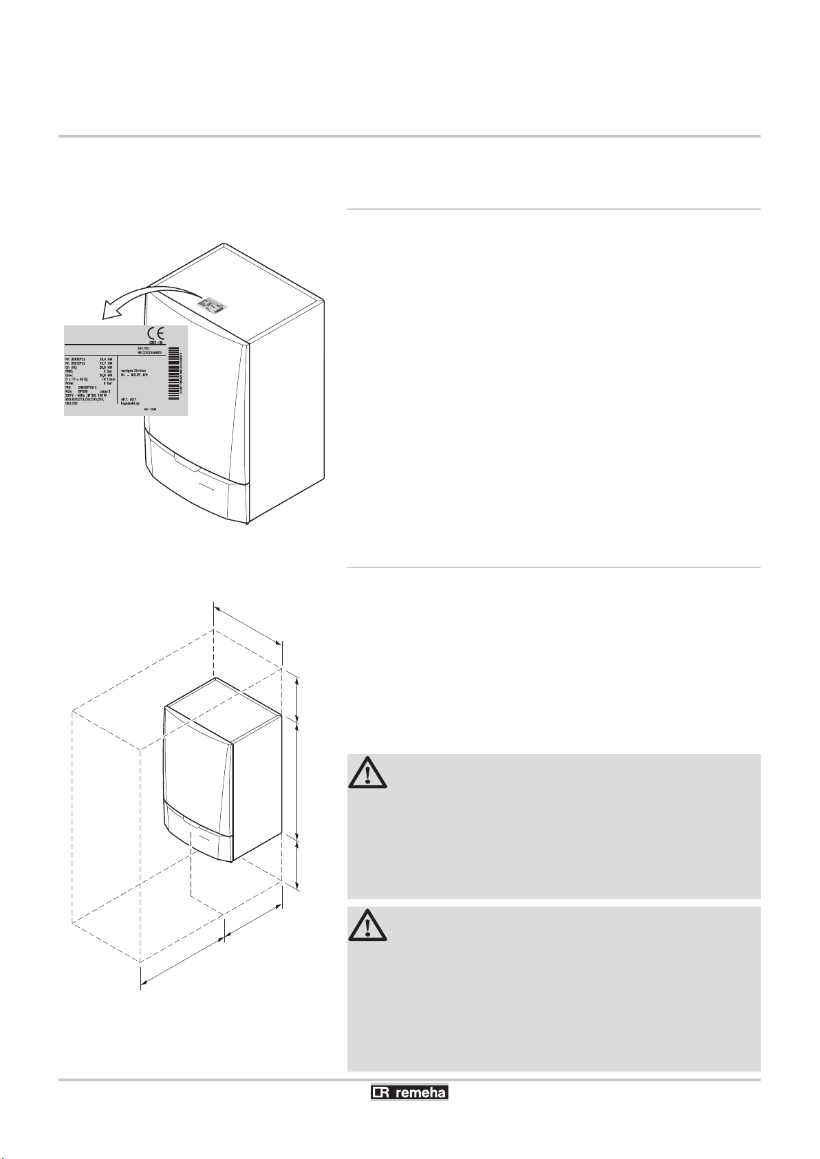
4.3.1. Data plate
The data plate located on top of the boiler provides important
information on the appliance: serial number, model, gas category, etc.
4.3.2. Location of the boiler
4 Before mounting the boiler, decide on the ideal position for
mounting, bearing the Directives and the dimensions of the
appliance in mind.
4 When choosing the position for mounting the boiler, bear in mind
the authorised position of the combustion gas discharge outlets
and the air intake opening.
4 To ensure adequate accessibility to the appliance and facilitate
maintenance, leave enough space around the boiler.
WARNING
4 Fix the appliance to a solid wall capable of bearing
the weight of the appliance when full of water and fully
equipped.
4 It is forbidden to store inflammable products and
materials in the boiler room or close to the boiler,
even temporarily.
CAUTION
4 The boiler must be installed in a frost-free
environment.
4 An earthed wall socket must be available close to the
boiler.
4 A connection to the mains drainage system for the
discharge of condensate must be available close to
the boiler.
22
040412 - 7600585-01
T000756-A
Z
OZ
1
0
B
2 3
60
225
240
T001532-A
min. 550
min.495
min. 250
50 (2)
min. 250
100
min. (1)
Calenta 25s - 28c - 35s - 40c 4. Installation
Safety rating
n
B
Z
OZ
Bathtub or shower tray
Zones
Breakdown of the exterior zone
For safety rating IP X4D, installation in the bathroom is possible in
zones 2 and 3 and in the breakdown of the exterior zone.
4 In this case, connect the 230V power supply as a fixed connection.
4 Also in this case, connect an air intake pipe.
CAUTION
In the case of a fixed connection to the power cord, you
must always install a main bipolar switch with an opening
gap of at least 3 mm (EN 60335-1).
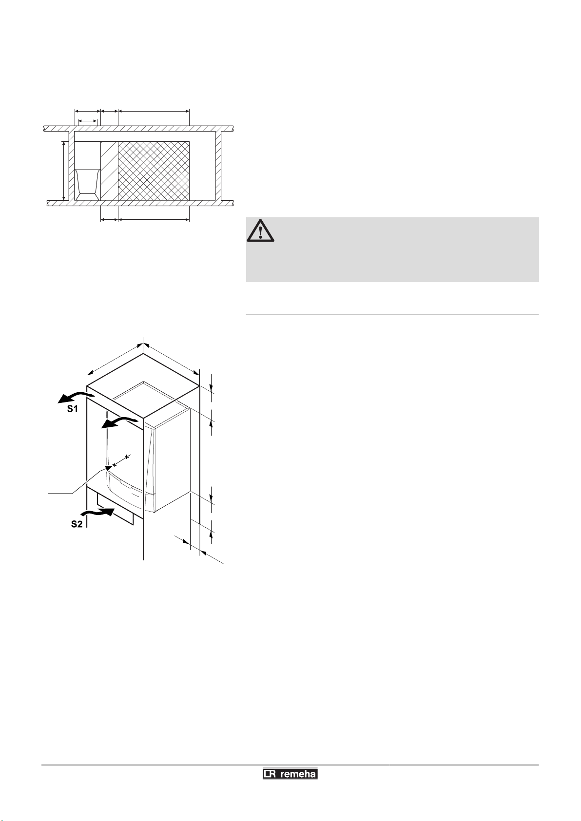
4.3.3. Ventilation
(1)
(2)
Distance between the front of the boiler and the internal
wall of the casing box.
Distance to allow on either side of the boiler.
If the boiler is installed in a closed casing, respect the minimum
dimensions given in the diagram opposite. Also allow openings to
obviate the following hazards:
4 Accumulation of gas
4 Heating of the box
Minimum cross section of the openings: S1 + S2 = 150 cm
2
040412 - 7600585-01
23
T000754-C
67
195
265
132
199
266
331
690
450
395
225
120
140
140
150
257,5
67
195
265
132
199
266
331
690
450
395
225
120
140
140
150
257,5
4. Installation Calenta 25s - 28c - 35s - 40c
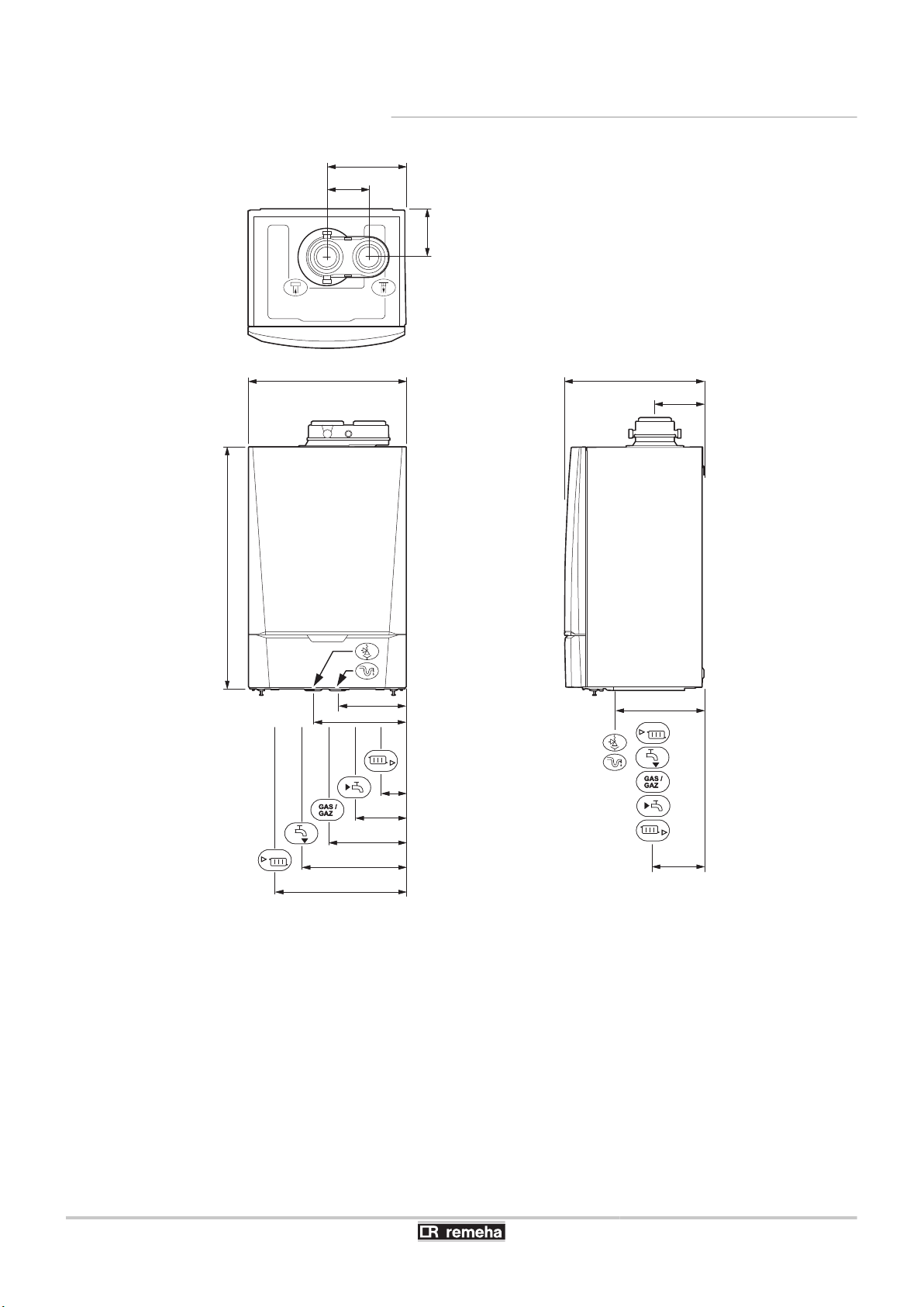
4.3.4. Main dimensions
i
h
ê
j
z
x
Gas /
Gaz
Connection of the combustion gas exhaust pipe; Ø 80 mm
Connection of the air intake pipe; Ø 80 mm
Safety valve outlet pipe; Ø 25 mm
Condensates discharge; Ø 25 mm
Heating circuit return; Clamping Ø 22 mm
Domestic cold water inlet; Clamping Ø 15 mm
Gas connection; Clamping Ø 15 mm
24
y
{
Domestic hot water outlet; Clamping Ø 15 mm
Heating circuit flow; Clamping Ø 22 mm
040412 - 7600585-01
T001540-A
2
1
5
4
3
Calenta 25s - 28c - 35s - 40c 4. Installation
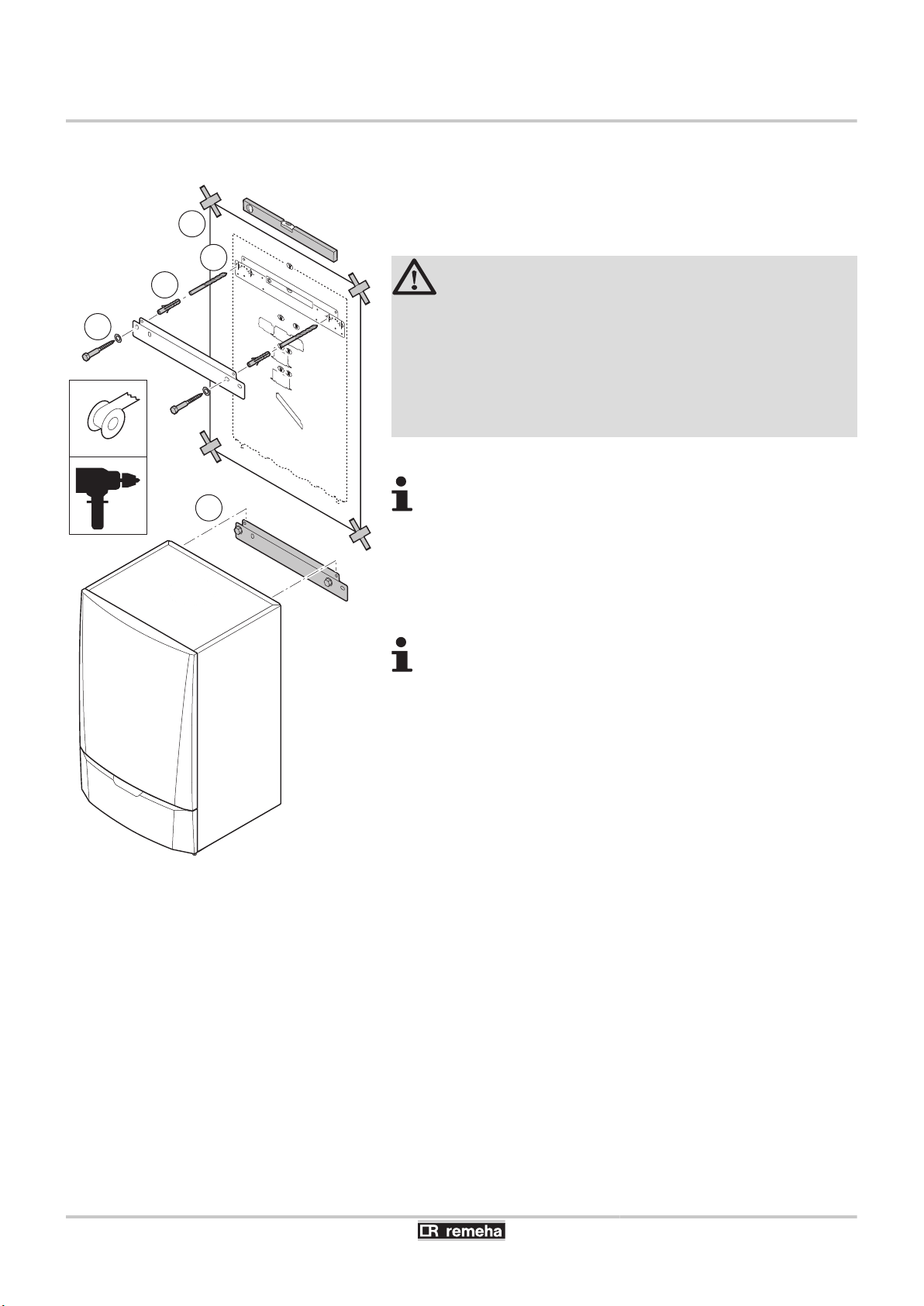
4.4 Positioning the boiler
The boiler is delivered with a mounting template.
A suspension clamp situated at the rear of the casing enables the
boiler to be directly suspended on the mounting bracket.
1. Position the mounting template to the wall with adhesive tape.
CAUTION
4 Using a spirit level, check that the mounting axis is
perfectly horizontal.
4 During mounting, cover up the connection points for
the air supply and the combustion gas exhaust, to
protect the boiler and its connections from dust. Only
remove this protection at the time when these
connections are made.
2. Drill 2 holes with a Ø of 10 mm.
Additional holes are provided in case one or other of the
standard locating holes prevents the correct location of the
plugs.
3. Insert the rawplugs with a Ø of 10 mm.
4. Attach the mounting bracket to the wall with the provided bolts with
a Ø of 10 mm.
5. Hang the boiler on the mounting bracket.
The relevant assembly instruction describes how to hang
the mounting frame (accessory).
040412 - 7600585-01
25
T001535-C
1
2
3
7
5
6
4
T001534-C
1
2
3
4
5
8
6
7
4. Installation Calenta 25s - 28c - 35s - 40c
4.5 Alternatives for hydraulic connections
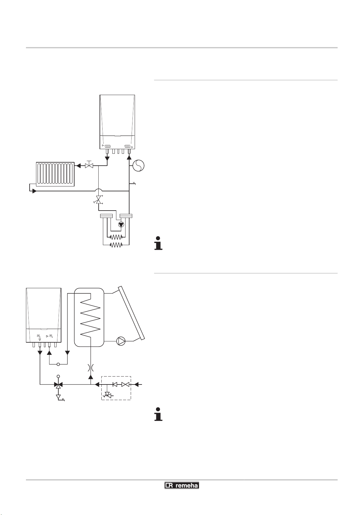
4.5.1. Connection of the underfloor heating
1
2
3
4
5
6
7
Boiler
Expansion vessel
Stopcock
Regulator valve
Filling/drainage valve
Underfloor heating
Heating by radiators
The boiler can be connected directly to an underfloor heating circuit.
If using plastic ducting (for the underfloor heating for example), the
plastic tubes must be totally oxygen-tight according to standard DIN
4726/4729. If the synthetic ducting used in the installation does not
conform to these standards, it is advisable to hydraulically separate
the boiler circuit from the central heating circuit by installing a plate
heat exchanger.
Parameters p"8 and p"9 are used to modify the
pump settings.
4.5.2. Connection of a solar hot water tank
1
2
3
4
5
6
7
8
Boilers, of the heating and domestic hot water production type, are
Boiler
Tank
Solar collector
Pump
Flow limiter
Safety unit
Mixer valve
Solar DHW sensor SCU-S02
suitable for reheating downstream from solar DHW tanks. A kit
(accessory) is available for the connection.
See the solar domestic hot water tank's technical notes for
more information concerning hydraulic connections.
26
040412 - 7600585-01
T004865-A
1
2
4
6
7
M
3
5
8
Calenta 25s - 28c - 35s - 40c 4. Installation
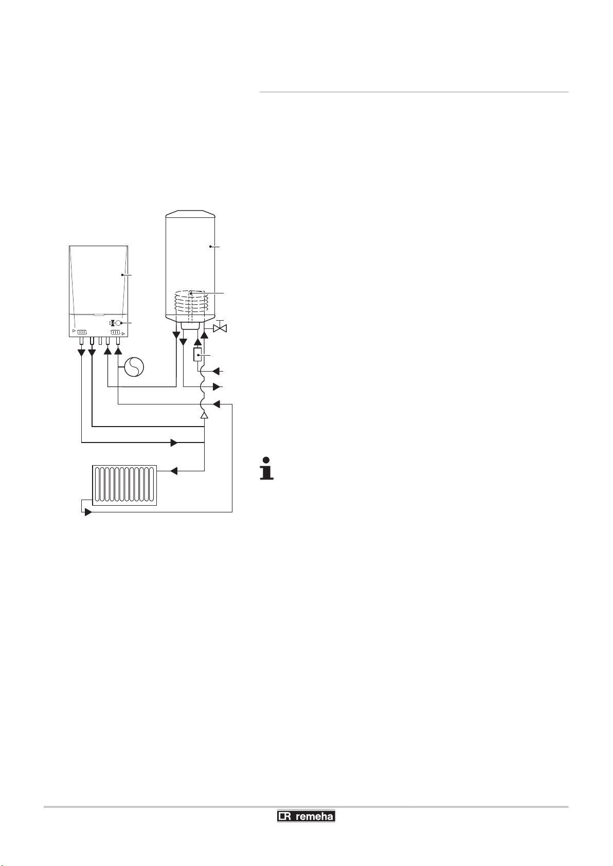
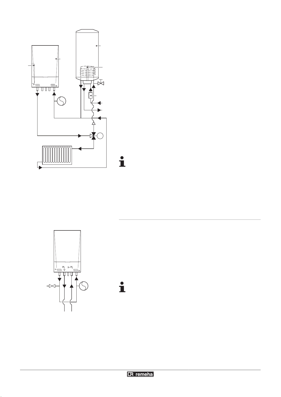
4.5.3. Connection of an independent hot water
tank
The standard version of the heating-only type of boiler is fitted with a
command for regulation of the hot water tank circuit. The command
is adjusted to switch preferentially to the hot water tank circuit. This
gives priority to the hot water tank when simultaneous requests for
heat come from the hot water tank and the central heating. The
indirectly heated calorifier can be connected using an internal or
external three-way valve.
Internal three-way valve
1
2
3
4
5
6
7
8
Boiler
Independent hot water tank
DHW sensor
Air vent kit of the hot water tank
Safety unit
Expansion vessel
Heating-Installation
3-way valve
The boiler connection kit must be used to install the three-way valve
in the boiler (Accessory). The three-way valve (230 V) is controlled
by the boiler control unit of the boiler.
¼ For the installation or mounting of any accessories, refer to the
mounting instructions delivered with the accessories in question.
4
A safety unit is installed at the point where cold water
arrives at the hot water tank to prevent backflow or
overpressure.
4 The central heating pipes for the boiler circuit must be
in Ø 22 mm (From Ø 15 mm to Ø 22 mm at the boiler
itself).
040412 - 7600585-01
27
T001537-C
1
2
4
8
6
7
M
3
5
9
T001536-B
1
2
3
4. Installation Calenta 25s - 28c - 35s - 40c
External three-way valve
1
2
3
4
5
6
7
8
9
Boiler
Independent hot water tank
DHW sensor
Air vent kit of the hot water tank
Safety unit
Expansion vessel
Heating-Installation
3-way valve
SCU-X02 control PCB
Control SCU-X02 must be used to install the three-way valve outside
of the boiler (Accessory). The three-way valve 24 V/230 V is
controlled by control SCU-X02. The control must be installed in the
electronics expansion kit (Accessory).
¼ For the installation or mounting of any accessories, refer to the
mounting instructions delivered with the accessories in question.
4 In order to prevent an uncontrolled flow in the heating
circuit, the return channel to the hot water tank must
always be connected directly to the return channel to
the boiler and therefore never directly connected to
the heating installation.
4 A safety unit is installed at the point where cold water
arrives at the hot water tank to prevent backflow or
overpressure.
4.5.4. Geyser use
1
2
3
The combi boiler can also be used solely for DHW operation. The
boiler can then function as a geyser. The central heating function has
to be switched off for this purpose, using parameter p3.
Boiler
Filling/drainage valve
Expansion vessel
The flow and return connections of the unit have to be
connected.
28
040412 - 7600585-01
 Loading...