

High-efficiency wall-hung condensing gas boilers
Calenta 25s - 28c - 35s - 40c
Netherlands
EN
Installation and
Service Manual
7600585-01

EG declaration of conformity
The device complies with the standard type described in the EG
declaration of conformity. It was manufactured and commissioned in
accordance with European directives.
The original of the declaration of compliance is available from the
manufacturer.

Contents
1 Introduction ................................................................................................6
1.1 Symbols used .......................................................6
1.2 Abbreviations ........................................................6
1.3 General ..................................................................6
1.3.1 Manufacturer's liability .............................................6
1.3.2 Installer's liability .....................................................7
1.4 Homologations ......................................................7
1.4.1 Certifications ...........................................................7
1.4.2 Equipment categories .............................................9
1.4.3 Additional Directives ................................................9
1.4.4 Factory test .............................................................9
2 Safety instructions and recommendations ............................................10
2.1 Safety instructions .............................................10
2.2 Recommendations ..............................................10
3 Technical description ..............................................................................12
3.1 General description ............................................12
3.2 Main parts ............................................................12
3.3 Operating principle .............................................13
3.3.1 Gas/air setting .......................................................13
3.3.2 Combustion ...........................................................14
3.3.3 Heating and domestic hot water production ..........14
3.3.4 Control system ......................................................14
3.3.5 Adjustment ............................................................14
3.3.6 Regulation of the water temperature .....................15
3.3.7 Protection against a shortage of water ..................15
3.3.8 Maximum temperature protection .........................15
3.3.9 Skeleton Diagrams ................................................16
3.3.10 Shunt pump ...........................................................16
3.3.11 Water flow rate ......................................................17
3.4 Technical specifications ....................................17
4 Installation ................................................................................................20
4.1 Regulations governing installation ...................20
4.2 Package list .........................................................20
4.2.1 Standard delivery ..................................................20
4.2.2 Accessories ...........................................................21
040412 - 7600585-01
1

Contents
4.3 Choice of the location ........................................22
4.3.1 Data plate ..............................................................22
4.3.2 Location of the boiler .............................................22
4.3.3 Ventilation .............................................................23
4.3.4 Main dimensions ...................................................24
4.4 Positioning the boiler .........................................25
4.5 Alternatives for hydraulic connections ............26
4.5.1 Connection of the underfloor heating ....................26
4.5.2 Connection of a solar hot water tank .....................26
4.5.3 Connection of an independent hot water
tank .......................................................................27
4.5.4 Geyser use ............................................................28
4.5.5 Solo use ................................................................29
4.6 Hydraulic connections .......................................29
4.6.1 Flushing the system ..............................................29
4.6.2 Connection of the heating circuit ...........................30
4.6.3 Hydraulic connection of the water circuit for domestic
use ........................................................................31
4.6.4 Connecting the expansion vessel .........................31
4.6.5 Connecting the condensate discharge pipe ..........31
4.7 Gas connection ...................................................32
4.8 Connections for the air and exhaust
pipes ....................................................................32
4.8.1 Classification .........................................................32
4.8.2 Outlets ...................................................................33
4.8.3 Lengths of the air/flue gas pipes ...........................34
4.8.4 Specific air/flue gas applications ...........................36
4.8.5 Additional Directives ..............................................36
4.8.6 Air/Exhaust adapter ...............................................37
4.8.7 Connection of the combustion gas exhaust
pipe .......................................................................38
4.8.8 Connection of the air intake pipe ...........................38
4.9 Electrical connections ........................................39
4.9.1 Control unit ............................................................39
4.9.2 Recommendations ................................................40
4.9.3 Standard control PCB ...........................................41
4.9.4 Connecting the room thermostat ...........................42
4.9.5 Connecting the outside temperature sensor ........43
4.9.6 Connect frost protection ........................................43
4.9.7 Connecting the calorifier sensor/thermostat .........44
4.9.8 PC/Laptop connection ...........................................45
4.9.9 Shutdown input .....................................................45
4.9.10 Release input ........................................................45
040412 - 7600585-01
4.10 Optional electrical connections ........................46
4.10.1 Connection options for the 0-10 V control PCB
(IF-01) ...................................................................46
4.10.2 Connection possibilities for the PCB (SCU-
S02) .......................................................................47
2

4.11 Electrical diagram ...............................................50
4.12 Filling the system ...............................................51
4.12.1 Water treatment ....................................................51
4.12.2 Filling the siphon ...................................................51
4.12.3 Filling the system ..................................................52
5 Commissioning ........................................................................................53
5.1 Control panel .......................................................53
5.1.1 Functions of the keys ............................................53
5.1.2 Meaning of the symbols on the display .................53
5.2 Check points before commissioning ................54
5.2.1 Preparing the boiler for commissioning .................54
5.2.2 Gas circuit .............................................................55
5.2.3 Hydraulic circuit .....................................................55
5.2.4 Electrical connections ...........................................55
5.3 Commissioning the boiler ..................................55
5.4 Gas settings ........................................................57
5.4.1 Adapting to another gas type ................................57
5.4.2 Setting the air/gas ratio (Full load) ........................57
5.4.3 Setting the air/gas ratio (Part load) ......................59
5.4.4 Basic setting for the gas/air ratio ...........................60
5.5 Checks and adjustments after
commissioning ...................................................60
5.5.1 Finalizing work ......................................................60
5.6 Reading out measured values ...........................61
5.6.1 Reading the various current values .......................61
5.6.2 Readout from the hour counter and percentage of
successful starts ....................................................62
5.6.3 Status and sub-status ...........................................63
5.7 Changing the settings ........................................64
5.7.1 Parameter descriptions .........................................64
5.7.2 Modification of the user-level parameters .............66
5.7.3 Modification of the installer-level parameters ........67
5.7.4 Setting the maximum heat input for central heating
operation ...............................................................68
5.7.5 Return to the factory settings ................................69
5.7.6 Carrying out an auto-detect ...................................70
5.7.7 Setting the manual mode ......................................70
5.7.8 Setting the legionella protection function ..............70
040412 - 7600585-01
3

Contents
6 Switching off the boiler ............................................................................71
6.1 Installation shutdown .........................................71
6.2 Frost protection ..................................................71
6.3 Switching off the central heating ......................72
6.4 Shutting down domestic hot water
production ...........................................................72
7 Checking and maintenance .....................................................................73
7.1 Maintenance message ........................................73
7.2 Preventive maintenance with automated service
message ..............................................................73
7.2.1 Resetting the automatic maintenance
message ................................................................74
7.2.2 Dealing with the next maintenance message and
starting the new maintenance period ....................74
7.3 Standard inspection and maintenance
operations ...........................................................75
7.3.1 Checking the hydraulic pressure ...........................75
7.3.2 Checking the ionization current .............................75
7.3.3 Checking the transfer capacity ..............................75
7.3.4 Checking the tightness of the flue gas evacuation and
air inlet connections ..............................................76
7.3.5 Checking combustion ............................................76
7.3.6 Checking the automatic air vent ............................77
7.3.7 Checking the safety valve .....................................77
7.3.8 Checking the siphon ..............................................77
7.3.9 Checking the burner and cleaning the heat
exchanger .............................................................78
7.4 Specific maintenance operations ......................79
7.4.1 Replacing the ionization/ignition electrode ............79
7.4.2 Cleaning the plate exchanger (domestic hot water
end) and the water filter cartridge .........................79
7.4.3 Replacing the 3-way valve ....................................82
7.4.4 Replacing the non-return valve .............................83
7.4.5 Assembling the boiler ............................................84
8 Troubleshooting .......................................................................................85
040412 - 7600585-01
8.1 Error codes ..........................................................85
8.2 Shutdowns and lock-outs ..................................88
8.2.1 Blockage ...............................................................88
8.2.2 Blocking .................................................................88
8.3 Error memory ......................................................90
8.3.1 Error readout memorised ......................................91
8.3.2 Deletion of the error display ..................................92
4

9 Spare parts ................................................................................................93
9.1 General ................................................................93
9.2 Spare parts ..........................................................93
040412 - 7600585-01
5

1. Introduction
1 Introduction
1.1 Symbols used
Calenta 25s - 28c - 35s - 40c
In these instructions, various danger levels are employed to draw the
user's attention to particular information. In so doing, we wish to
safeguard the user's safety, obviate hazards and guarantee correct
operation of the appliance.
DANGER
Risk of a dangerous situation causing serious physical
injury.
WARNING
Risk of a dangerous situation causing slight physical
injury.
1.2 Abbreviations
1.3 General
CAUTION
Risk of material damage.
Signals important information.
¼ Signals a referral to other instructions or other pages in the
instructions.
4 3CE: Collective conduit for sealed boiler
4 Central heating: Central heating
4 COP: Energy performance
4 DHW: Domestic hot water
4 HRU: Heat Recovery Unit
1.3.1. Manufacturer's liability
Our products are manufactured in compliance with the requirements
of the various applicable European Directives. They are therefore
delivered with [ marking and all relevant documentation.
6
040412 - 7600585-01
Calenta 25s - 28c - 35s - 40c
1. Introduction
In the interest of customers, we are continuously endeavouring to
make improvements in product quality. All the specifications stated in
this document are therefore subject to change without notice.
Our liability as the manufacturer may not be invoked in the following
cases:
4 Failure to abide by the instructions on using the appliance.
4 Faulty or insufficient maintenance of the appliance.
4 Failure to abide by the instructions on installing the appliance.
1.3.2. Installer's liability
The installer is responsible for the installation and inital start up of the
appliance. The installer must respect the following instructions:
4 Read and follow the instructions given in the manuals provided
with the appliance.
4 Carry out installation in compliance with the prevailing legislation
and standards.
4 Perform the initial start up and carry out any checks necessary.
4 Explain the installation to the user.
4 If a maintenance is necessary, warn the user of the obligation to
check the appliance and maintain it in good working order.
4 Give all the instruction manuals to the user.
1.4 Homologations
1.4.1. Certifications
CE identification no
NOx classification
Type of connection
(Flue gas outlet)
Depending on the type of appliance and the gross heat
requirements for domestic water in accordance with NEN
5128, efficiency values up to 0,825 can be applied to
determine EPC.
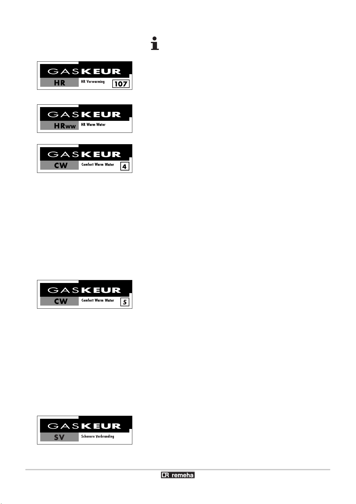
Approval labels for gas
n
The boiler has been given several approval labels for gas. Stichting
Energie Prestatiekeur grants these independent labels on
performance to gas consumption appliances that meet specific
provisions on a certain number of aspects (efficiency, environmental
friendliness, comfort). The labels have the following meaning:
PIN 0063BT3444
5 (EN 297 pr A3, EN 656)
B23 , B
C
93
, B33 , C13 , C33 , C43 , C53 , C63 , C83 ,
23P
040412 - 7600585-01
7
T001057-A
T001058-A
T001055-A
T001795-A
T001059-A
1. Introduction
Calenta 25s - 28c - 35s - 40c
The labels are not guaranteed if the boiler is adapted to
G20 or G31.
HR 107 gas approval (High efficiency heating)
This means that the efficiency of the boiler when producing heating
water is 107% higher than the Gaskeur HR criterion in relation to
Hi. This means that the boiler is economical and therefore less costly
and more environmentally friendly.
HRww gas approval (High efficiency hot water)
This implies that the hot water/heating boiler produces hot water
economically and efficiently, without wasting energy or water
therefore.
CW 4 gas approval (Hot water comfort)
This means that, for the preparation of hot water, the Calenta 28c
satisfies application class 4. With the application of class 4, the
Calenta 28c is appropriate for:
4 A draw-off flow rate of at least 7,5 l/min at 60°C.
4 A shower function from 6 l/min up to at least 12,5 l/min at 40°C.
4 Filling a bathtub in less than 11 minutes with 120 litres of water at
40°C on average.
The simultaneity of these functions is not a requirement.
Parameters for which the performance of the Calenta 28c boiler
complies with the Hot Water Comfort classification:
4 Rotation speed on start-up 3000 rpm.
4 Maximum DHW rate 6200 rpm.
4 Energy-saving mode: Stop.
CW 5 gas approval (Hot water comfort)
This means that, for the preparation of hot water, the Calenta 40c
satisfies application class 5. With the application of class 5, the
Calenta 40c is appropriate for:
4 Hot water comfort.
4 A shower function from 6 l/min up to at least 12,5 l/min at 40°C.
4 Filling a bathtub in less than 10 minutes with 150 litres of water at
40 °C on average.
The simultaneity of these functions is not a requirement.
Parameters for which the performance of the Calenta 40c boiler
complies with the Hot Water Comfort classification:
4 Rotation speed on start-up 4000 rpm.
4 Maximum DHW rate 6800 rpm.
4 Energy-saving mode: Stop.
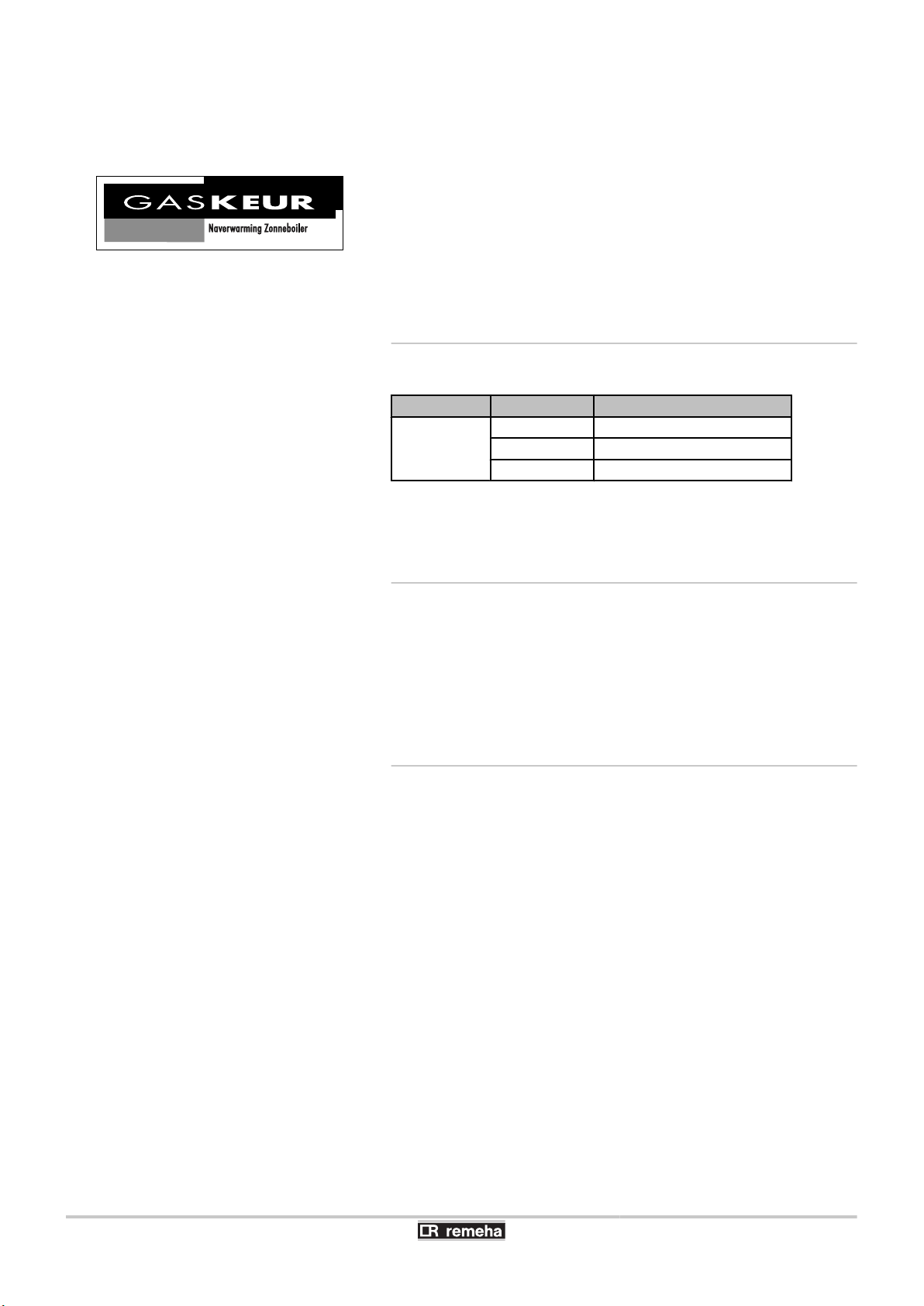
SV gas approval (Clean combustion)
8
040412 - 7600585-01
T001779-B
NZ
Calenta 25s - 28c - 35s - 40c
1. Introduction
This means that the boiler complies with the NOx Order and
provisions on clean combustion. The boiler has a gas/air coupling
combined with a fully premixed burner. For this reason, the emission
of NOx and CO is as low as possible.
NZ gas approval (Solar water heater reheating)
This implies that the hot water/heating boiler can operate on reheating
for solar water heaters. The label (solar water heater reheating) is
valid in combination with the connection kit for solar water heaters.
Owing to the possible formation of legionella, the boiler must not be
shut down or the DHW temperature set below 60°C.
1.4.2. Equipment categories
Gas category
II
, I
2L3P
2H
Gas type Connection pressure (mbar)
G20 (Gas H) 20
G25 (Gas L) 25
G31 (Propane) 30/50
The boiler is preset in the factory to operate on natural gas G25 (Gas
L).
1.4.3. Additional Directives
Apart from the legal provisions and Directives, the additional
Directives described in these instructions must also be observed.
For all provisions and Directives referred to in these instructions, it is
agreed that all addenda or subsequent provisions will apply at the
time of installation.
1.4.4. Factory test
Before leaving the factory, each boiler is set for optimum performance
and tested to check the following items:
040412 - 7600585-01
4 Electrical safety
4 Adjustment (CO2)
4 Domestic hot water mode (Only on models with domestic hot water
production)
4 Water tightness
4 Gas tightness
4 Parameter settings
9
2. Safety instructions and recommendations
2 Safety instructions and
recommendations
2.1 Safety instructions
DANGER
If you smell gas:
1. Do not use a naked flame, do not smoke, do not
operate electrical contacts or switches ( doorbell,
light, motor, lift, etc..).
2. Shut off the gas supply.
3. Open the windows.
4. Trace possible leaks and seal them immediately.
5. If the gas leak is before the gas meter, contact the
gas supplier.
Calenta 25s - 28c - 35s - 40c
2.2 Recommendations
DANGER
If you smell flue gases:
1. Switch the appliance off.
2. Open the windows.
3. Trace possible leaks and seal them immediately.
WARNING
4 Installation and maintenance of the boiler must be
carried out by a qualified professional in compliance
with prevailing local and national regulations.
4 When working on the boiler, always disconnect the
boiler from the mains and close the main gas inlet
valve.
4 After maintenance or repair work, check all
installations to ensure that there are no leaks.
CAUTION
10
The boiler must be installed in a frost-free environment.
Keep this document close to the place where the boiler is
installed.
Casing components
040412 - 7600585-01

Calenta 25s - 28c - 35s - 40c 2. Safety instructions and recommendations
Only remove the casing for maintenance and repair operations. Put
the casing back in place after maintenance and repair operations.
Instructions stickers
The instructions and warnings affixed to the appliance must never be
removed or covered and must remain legible during the entire lifespan
of the appliance. Immediately replace damaged or illegible
instructions and warning stickers.
Modifications
Modifications may only be made to the boiler after the written
permission of Remeha to do so.
040412 - 7600585-01
11
T000822-B T000822-D
9
8
7
6
4
5
2
3
10
12
14
13
16
17
19
20
18
15
1 21
11
3. Technical description Calenta 25s - 28c - 35s - 40c
3 Technical description
3.1 General description
High-efficiency wall-hung condensing gas boilers
4 High efficiency heating.
4 Low pollutant emissions.
Boiler type:
4 Calenta 25s - 35s: Heating only (Production of domestic hot water
can be ensured by a separate hot water calorifier).
4 Calenta 28c - 40c: Heating and domestic hot water production.
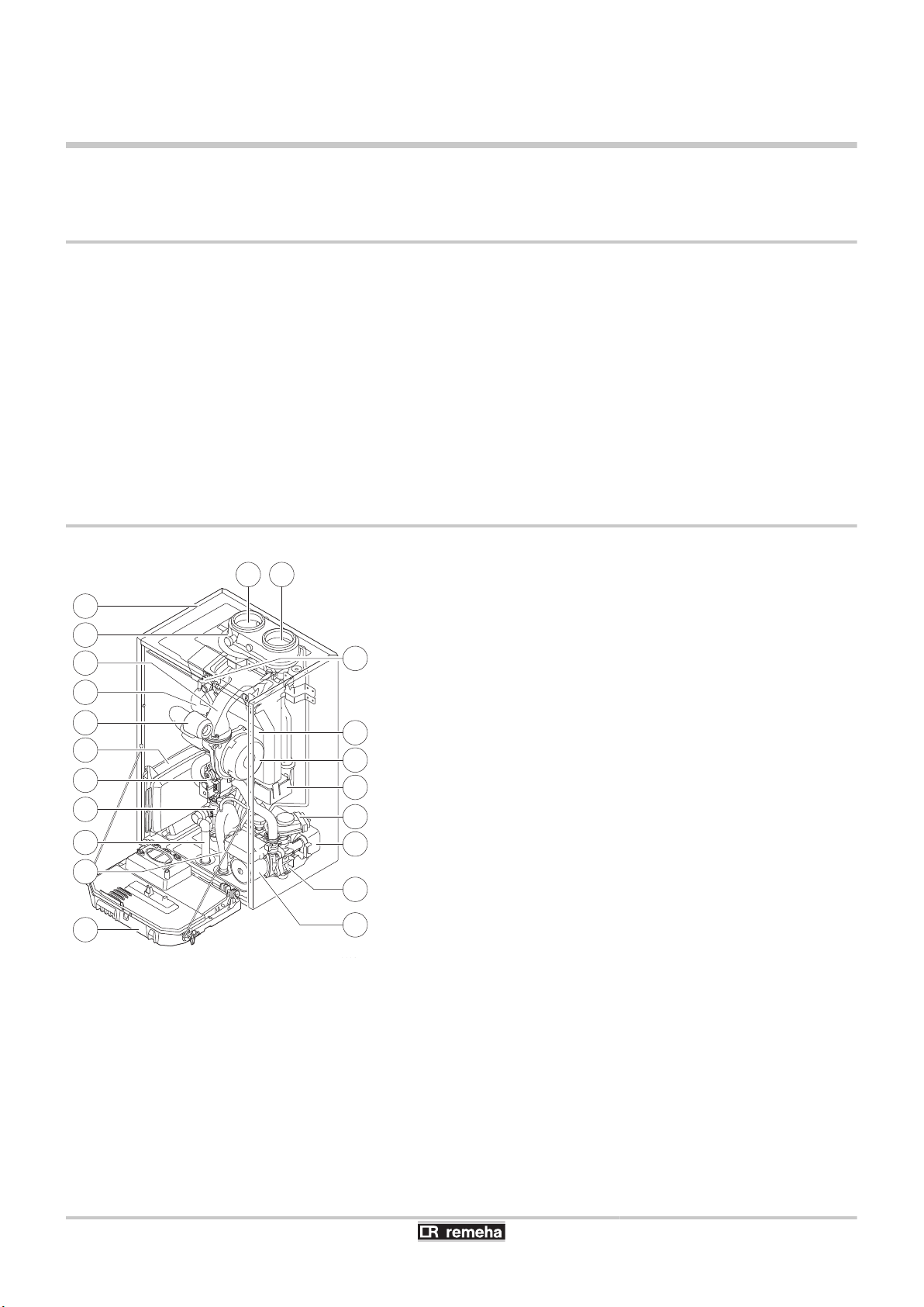
3.2 Main parts
Calenta 25s - 28c
1
2
3
4
5
6
7
8
9
10
11
12
13
14
15
Flue gas outlet
Casing/air box
Outlet for measuring combustion gases
Mixer pipe
Heating flow hose
Air intake silencer
Box for the control PCBs (accessory)
Combined venturi and gas valve unit
Flow end hydroblock
Safety valve outlet pipe
Siphon
Instrument box
Shunt pump
Return end hydroblock
Plate heat exchanger (DHW) (Only on models with
domestic hot water production)
12
16
17
18
19
20
21
3-way valve (Only on models with domestic hot water
production)
Condensate receiver tank
Fan
Heat exchanger (Central heating)
Ignition/ionization electrode
Air intake
040412 - 7600585-01
T002886-C
2
14
16
15
13
17
18
19
20
3
4
5
6
7
8
9
10
11
12
1 21
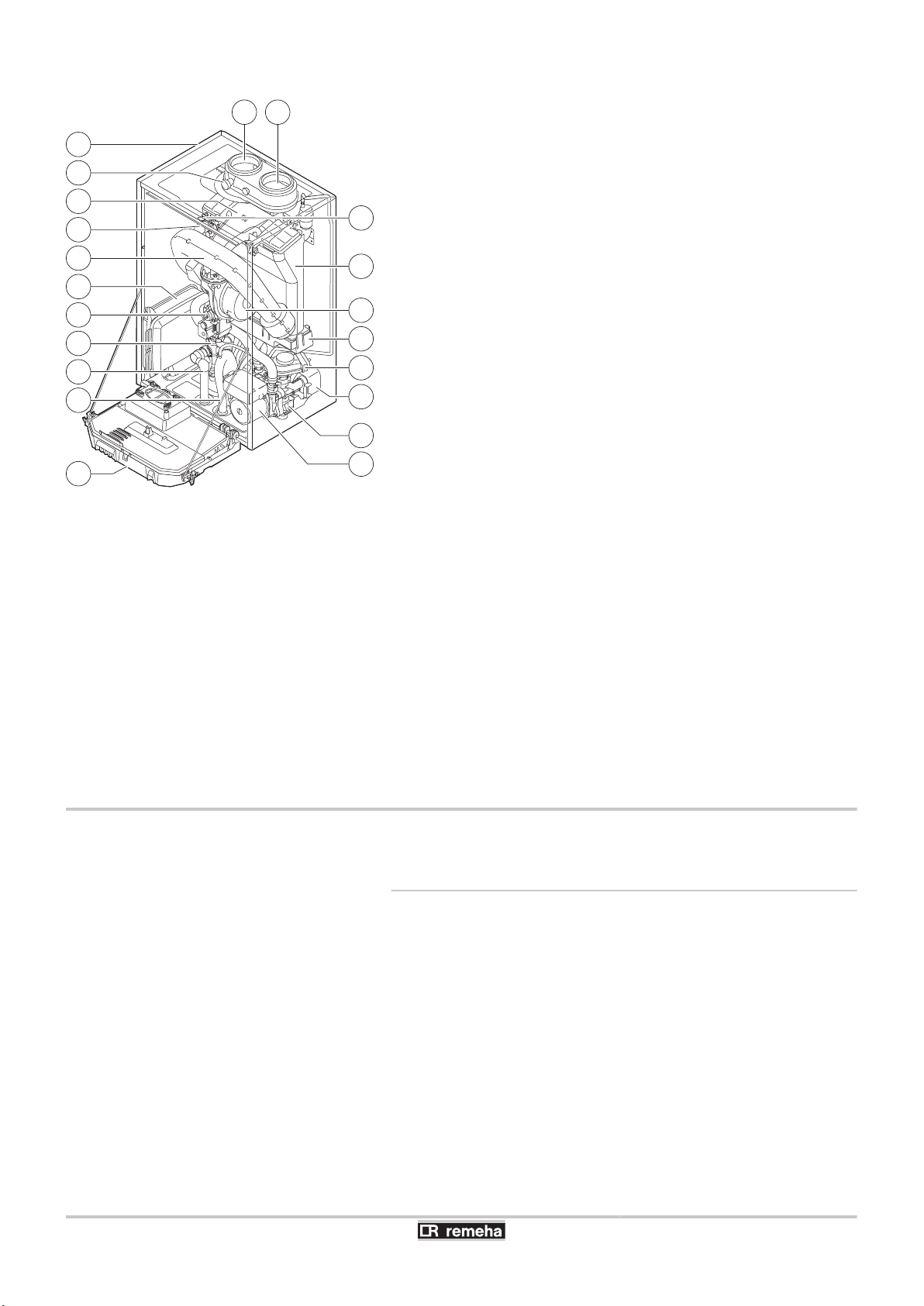
Calenta 25s - 28c - 35s - 40c
3. Technical description
Calenta 35s - 40c
1
2
3
4
5
6
7
8
9
10
11
12
13
14
15
16
Flue gas outlet
Casing/air box
Outlet for measuring combustion gases
Mixer pipe
Heating flow hose
Air intake silencer
Box for the control PCBs (accessory)
Combined venturi and gas valve unit
Flow end hydroblock
Safety valve outlet pipe
Siphon
Instrument box
Shunt pump
Return end hydroblock
Plate heat exchanger (DHW) (Only on models with
domestic hot water production)
3-way valve (Only on models with domestic hot water
production)
3.3 Operating principle
17
18
19
20
21
Condensate receiver tank
Fan
Heat exchanger (Central heating)
Ignition/ionization electrode
Air intake
3.3.1. Gas/air setting
The casing fitted to the boiler is also used as an air box. Air is sucked
in by the fan and gas injected into the venturi by the fan intake. The
fan rotation speed is set according to the settings parameters, the
thermal energy requirement and the temperatures measured by the
temperature sensors. The gas and air are mixed in the venturi. The
gas/air ratio ensures that the quantities of gas and air are adjusted to
each other. This provides optimum combustion on the entire output
range. The gas/air mixture is fed into the burner on top of the
exchanger.
040412 - 7600585-01
13

3. Technical description
Calenta 25s - 28c - 35s - 40c
3.3.2. Combustion
The burner heats the heating water circulating in the heat
exchanger. At a return temperature lower than around 55°C, the flue
gases cool down to a temperature lower than the dew point, thus
causing the condensation of the water vapour contained in the flue
gases in the back side of the heat exchanger. The heat released
during this condensation process (the latent heat or condensing heat)
is also transferred to the heating water. The cooled combustion gases
are evacuated via the combustion gas outlet flue. The condensation
water is evacuated via a siphon.
3.3.3. Heating and domestic hot water production
On heating and domestic hot water production type boilers, an
integrated plate exchanger heats the domestic water. A 3-way valve
determines whether the heated water is fed into the heating system
or the plate exchanger. A pick-up sensor signals that a hot water tap
is being opened. This signal is transmitted to the control panel, which
then switches the 3-way valve to the hot water position and trips the
heating pump. The 3-way valve is spring-loaded but only consumes
electricity when it switches to another position.
The heating water reheats the domestic water in the plate
exchanger. In comfort mode, if there is no hot water draw-off, the
boiler handles the periodic reheating of the plate exchanger. Any
limescale particles are kept out of the plate exchanger by a selfcleaning water filter (self-cleans once every 76 hours).
3.3.4. Control system
The boiler command, called Comfort Master©, handles a reliable
heat supply. This means that the boiler treats external negative
influences in a practical manner (notably when the water-flow is
insufficient or there are problems with air supply). In the presence of
such influences, the boiler doesn't switch into locking mode, but first
reduces his power and, depending on the nature of the
circumstances, will be temporarily out of service (blocking or stop).
The boiler will continue to supply heat as long as the situation does
not become dangerous.
3.3.5. Adjustment
The power of the boiler can be adjusted in the following ways:
14
4 On/Off setting
The output between the minimum and maximum values varies
based on the heating flow set point temperature.
4 Adjustable control
The output between the minimum and maximum values varies
based on the heating flow temperature determined by the
modulating control system.
4 Analogue setting (0-10 V)
040412 - 7600585-01

T003757-A
1 2 3
Calenta 25s - 28c - 35s - 40c 3. Technical description
1
2
3
Celcia 10
qSense
iSense
It is possible to connect a 2-wire on/off thermostat to the boiler such
as the Celcia 10 or a power stealing thermostat. The boiler output
can be modulated by an OpenTherm system with an appropriate
modulating thermostat such as the qSense or the iSense.
3.3.6. Regulation of the water temperature
The boiler is fitted with an electronic temperature regulator having an
outlet and return temperature probe. The flow temperature can be set
between 20°C and 90°C. The boiler reduces its power when the set
outlet-temperature is attained. The cutout temperature is the set
heating outlet-temperature + 5 °C.
3.3.7. Protection against a shortage of water
The boiler is fitted with a safety device to prevent the shortage of water
based on temperature measurements. By reducing its output when
the water flow rate is in danger of becoming insufficient, the boiler
continues to operate as long as possible. If the flow rate is too weak
ΔT ≥ 50°C or the heating flow temperature increases too much, the
boiler is locked for 10 minutes, code 5t[09. When there is no
water in the boiler or the pump is not running, the boiler goes into
safety shutdown, code e[10 at ΔT ≥ 70°C.
3.3.8. Maximum temperature protection
The overheating safety device locks the boiler when the water
temperature is too high (110°C), code e[12.
¼ For more detailed information, see chapter: "Error codes",
page 85
040412 - 7600585-01
15
R000124-A
1
4
2 3
T001874-A
1
2
3
9
8
4 5 6 7
T002537-B
0 200 400 600 800 1000 1200
Q (l/h)
10 kW
15 kW
20 kW
25 kW
615
545
435
295
437 623 830 1037
0
100
200
300
400
500
700
H (mbar)
600
3. Technical description Calenta 25s - 28c - 35s - 40c
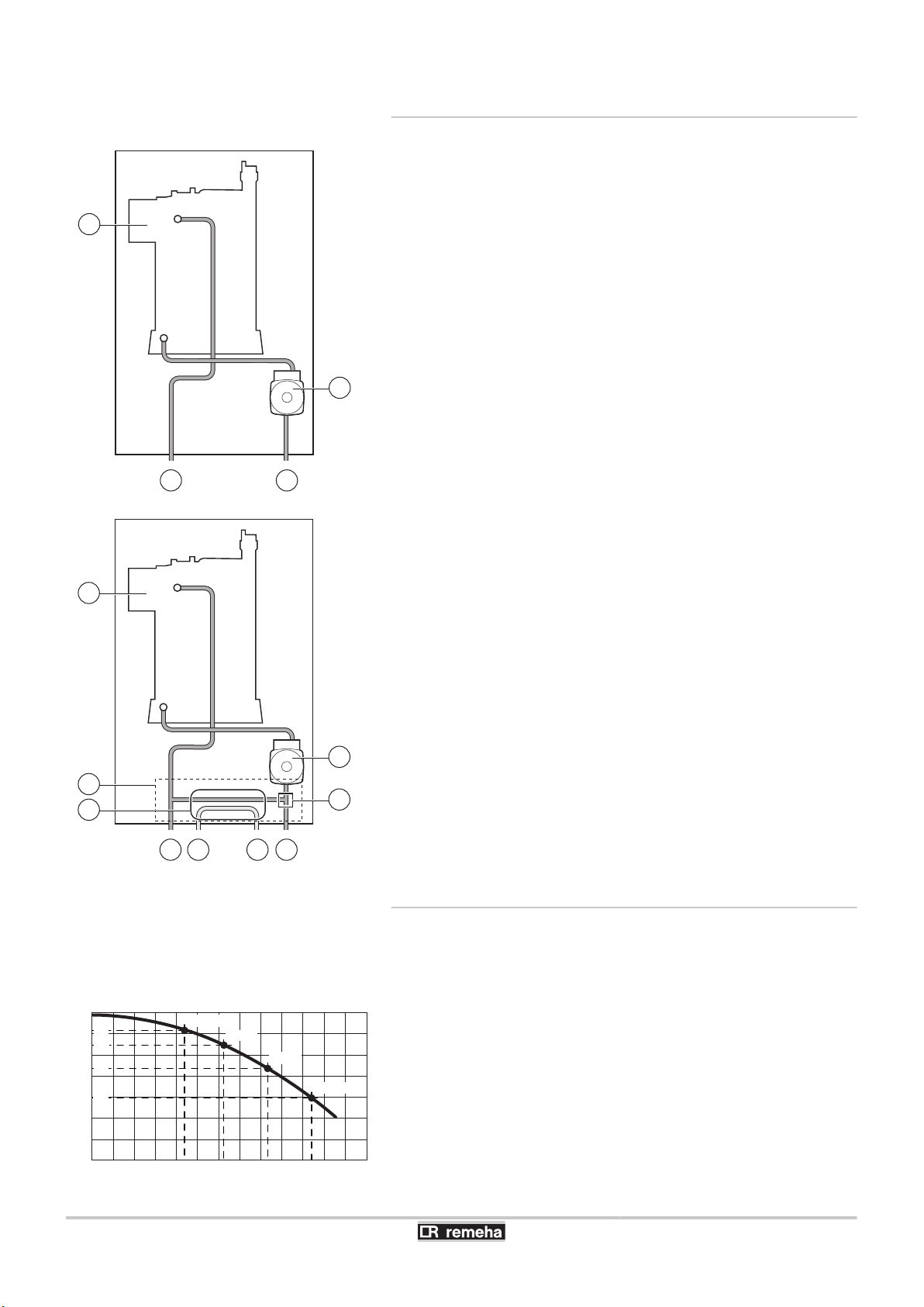
3.3.9. Skeleton Diagrams
Calenta 25s - 35s
1
2
3
4
Heat exchanger (Central heating)
Heating flow
Heating return
Shunt pump (Central heating)
Calenta 28c - 40c
1
2
3
4
Heat exchanger (Central heating)
Hydroblock
Plate heat exchanger (DHW)
Heating flow
16
5
6
7
8
9
Domestic hot water outlet
Domestic cold water inlet
Heating return
3-way valve
Shunt pump (Central heating)
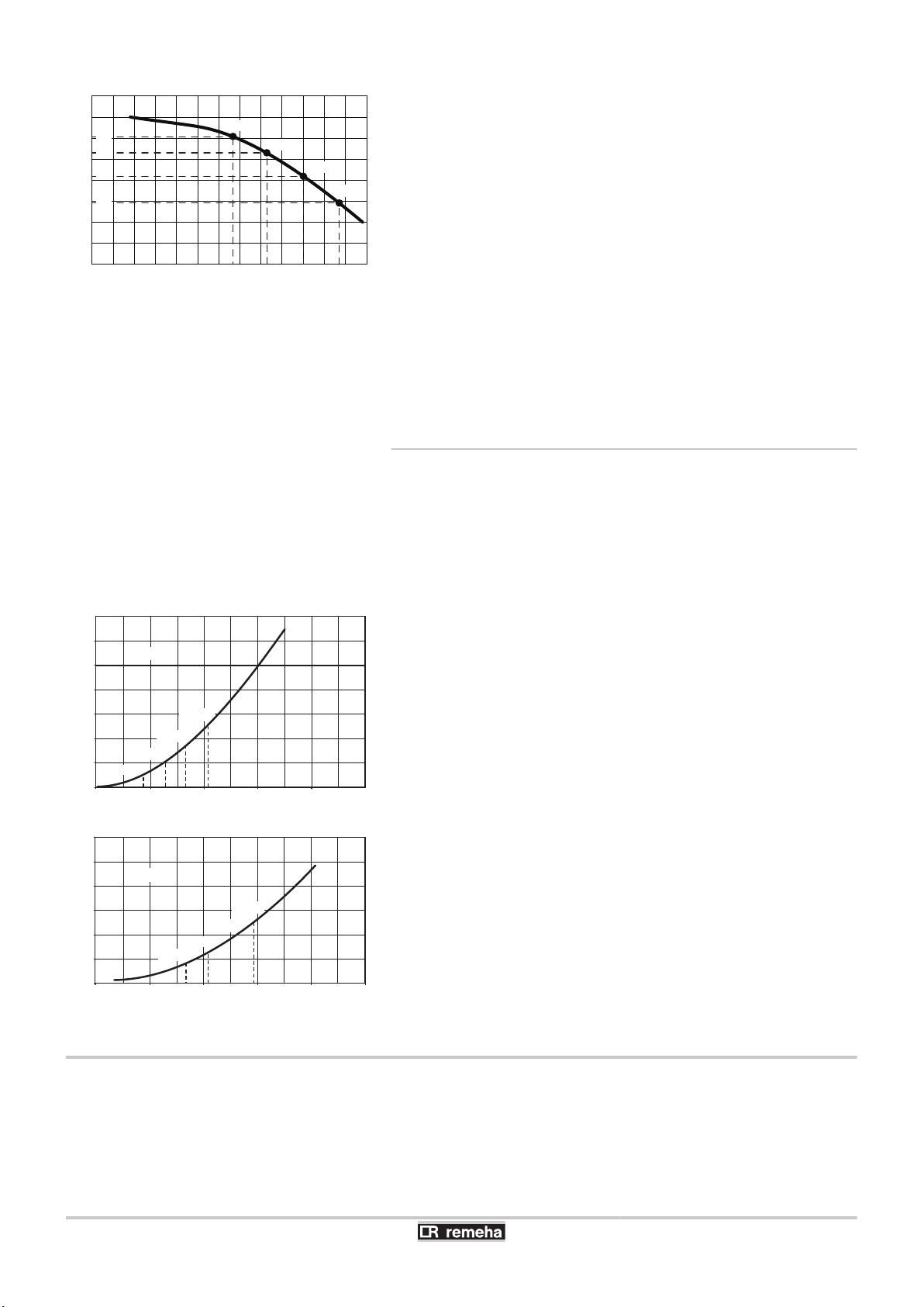
3.3.10. Shunt pump
The boiler is equipped with a circulating pump. This energy-efficient,
modulating circulating pump is controlled by the control unit based on
ΔT. The graph shows the manometric height at various outputs.
Calenta 25s - 28c
H
Q
Manometric height central heating circuit
Water flow
040412 - 7600585-01
T001748-B
0 250 500 750 1000 1250
0
100
200
300
400
500
700
800
H (mbar)
Q (l/h)
600
20 kW
25 kW
30 kW
35 kW
835 1252 1038
1465
606
418
530
291
T001978-A
0
100
200
300
400
500
600
700
0 500
1037437
15001000 2000 2500
∆p [mbar]
Q [l/h]
623 830
∆T = 20K
10 kW
15 kW
20 kW
25 kW
T001749-B
0
100
200
300
400
500
600
0 500
1043 1252 1465835
15001000 2000 2500
∆p [mbar]
Q [l/h]
∆T = 20K
20 kW
25 kW
30 kW
35 kW
Calenta 25s - 28c - 35s - 40c
3. Technical description
Calenta 35s - 40c
H
Q
Manometric height central heating circuit
Water flow
Parameters p"8 and p"9 are used to modify the pump settings:
4 If there are audible flowing noises in the system, the maximum
pump speed must be lowered using parameter p"9 (First of all,
vent the heating system).
4 If there is insufficient flow in the radiators or if they do not warm
up completely, the minimum pump speed can be increased using
parameter p"8.
¼ See chapter: "Modification of the installer-level parameters",
page 67.
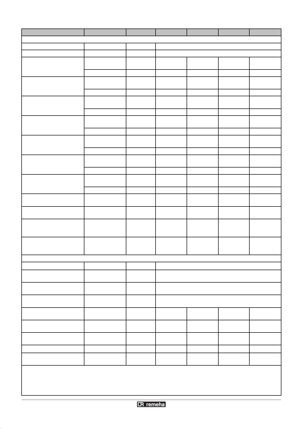
3.3.11. Water flow rate
The boiler's modulating control system limits the maximum difference
in temperature between the heating flow and return and the maximum
speed at which the flow temperature increases. In this way, the boiler
does not require a minimum water flow rate.
¼ If using thermostatic valves, see chapter: "Hydraulic
connections", page 29.
Calenta 25s
3.4 Technical specifications
040412 - 7600585-01
Δp
Q
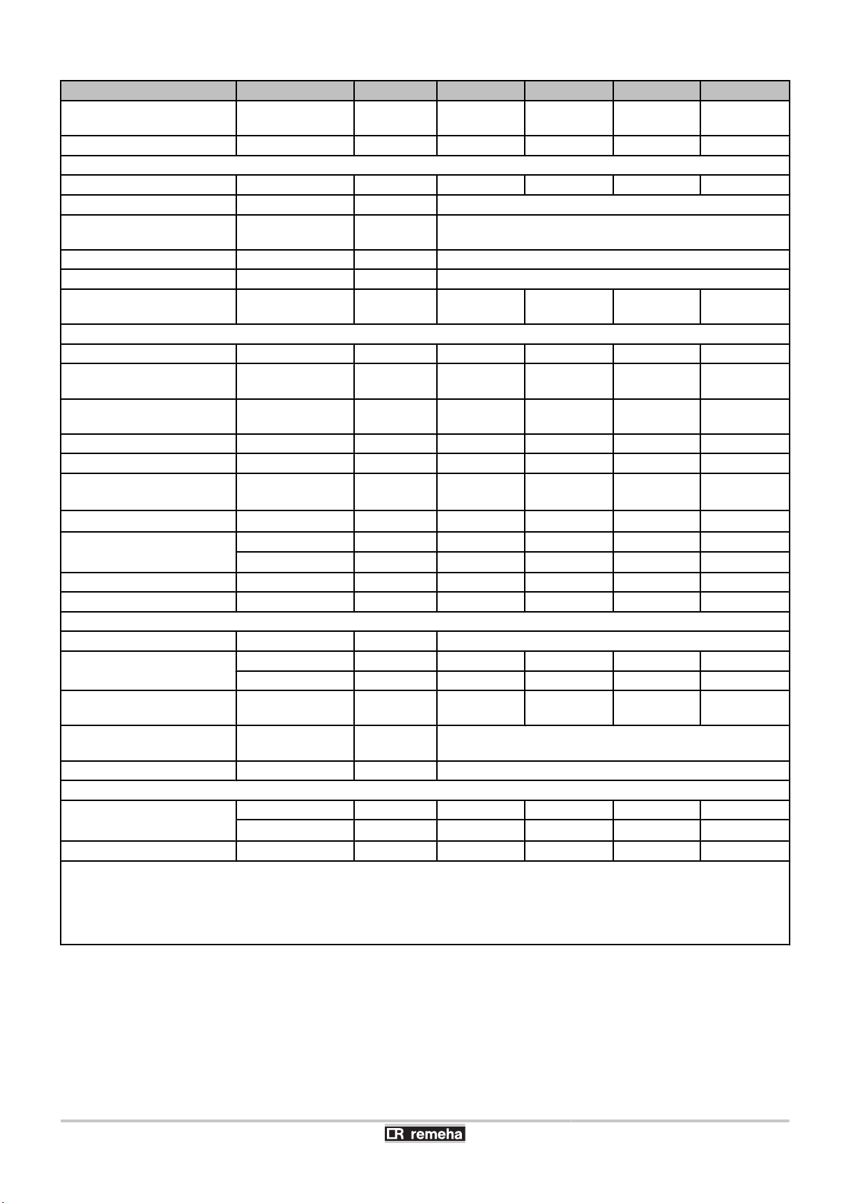
Calenta 35s
Δp
Q
Pressure drop
Water flow (max = 1680 l/h)
Pressure drop
Water flow (max = 2460 l/h)
17
3. Technical description Calenta 25s - 28c - 35s - 40c
Boiler type Calenta
25s 28c 35s 40c
General
EC indentification no. PIN
Flow rate setting Adjustable
Nominal output (Pn)
Heating System (80/60 °C)
Nominal output (Pn)
Heating System (50/30 °C)
Nominal output (Pn)
DHW System
Nominal input (Qn)
Heating System (Hi)
Nominal input(Qn)
Heating System (Hs)
Nominal input (Qnw)
DHW System (Hi)
Nominal input (Qnw)
DHW System (Hs)
Heating efficiency under full
load (Hi) (80/60 °C)
Heating efficiency under full
load (Hi) (50/30 °C)
minimummaximum
Factory setting kW 24,1 19,4 34,0 23,3
minimummaximum
Factory setting kW 25,5 20,5 35,9 24,5
minimummaximum
Factory setting kW - 28,6 - 39,7
minimummaximum
Factory setting kW 25,0 20,1 35,1 24,0
minimummaximum
Factory setting kW 27,8 22,3 39,0 26,7
minimummaximum
Factory setting kW - 28,0 - 38,8
minimummaximum
Factory setting kW - 31,1 - 43,1
- % 96,3 96,3 96,9 96,9
- % 102,0 102,0 102,2 102,2
kW 5,0 - 24,1 5,0 - 24,1 6,3 - 34,0 6,3 - 34,0
kW 5,6 - 25,5 5,6 - 25,5 7,0 - 35,9 7,0 - 35,9
kW - 5,0 - 28,6 - 6,3 - 39,7
kW 5,2 - 25,0 5,2 - 25,0 6,5 - 35,1 6,5 - 35,1
kW 5,8 - 27,8 5,8 - 27,8 7,2 - 39,0 7,2 - 39,0
kW - 5,2 - 28,0 - 6,5 - 38,8
kW - 5,8 - 31,1 - 7,2 - 43,1
Modulating, Start/Stop, 0 - 10 V
0063BT3444
Heating efficiency under
partial load (Hi) (Return
- % 96,1 96,1 96,3 96,3
temperature 60°C)
Heating efficiency under
partial load (EN 92/42)
- % 108,0 108,0 108,2 108,2
(Return temperature 30°C)
Data on the gases and combustion gases
Gas categories
Gas inlet pressure G20 (GasH)minimum-
- I
2L3P
and I
mbar 17 - 30
2H
maximum
Gas inlet pressure G25 (GasL)minimum-
mbar 20 - 30
maximum
Gas inlet pressure G31
(Propane)
Gas consumption G20 (GasH)minimum-
minimummaximum
mbar 30 - 50
m3/h
0,55 - 2,65 0,55 - 2,96 0,69 - 3,71 0,69 - 4,11
maximum
Gas consumption G25 (GasL)minimum-
m3/h
0,64 - 3,08 0,64 - 3,45 0,80 - 4,32 0,80 - 4,78
maximum
Gas consumption G31
(Propane)
NOx-Emission per year (n =1)
Mass flue gas flow rate minimum-
minimummaximum
m3/h
mg/kWh 38 38
0,21 - 1,02 0,21 - 1,15 0,27 - 1,44 0,27 - 1,59
42 42
kg/h 8,9 - 42,1 8,9 - 47,1 11,1 - 57,3 11,1 - 63,9
maximum
(1) Time needed as of the start of water draw-off to obtain an increase in temperature of 40K at the appliance's water outlet for the purposes of
installation calculation, based on the draw-off flow rate CW.
(2) The specific length of the pipe Ø 10/12 mm is the maximum uninsulated length, on the understanding that, in the most unfavourable summer
situation, the appliance will supply hot water in less than 30 s with a permanent increase in temperature of 35 ºC at the draw-off point in the
kitchen.
(3) Front panel removed
18
040412 - 7600585-01
Calenta 25s - 28c - 35s - 40c 3. Technical description
Boiler type Calenta
Flue gas temperature minimum-
maximum
Maximum counter pressure
Characteristics of the heating circuit
Water content
Water operating pressure minimum bar 0,8
Water operating pressure
(PMS)
Water temperature maximum °C 110
Operating temperature maximum °C 90
Manometric height central
heating circuit (ΔT = 20K)
Characteristics of the domestic hot water circuit
CW gas approval
Specific hot water flow D
(60 °C)
Specific hot water flow D
(40 °C)
Domestic water resistance
Flow rate threshold minimum l/min - 1,2 - 1,2
Actual appliance waiting
(1)
time
Specific pipe length
Annual operational efficiency
for domestic water
Water content
Operating pressure (Pmw) maximum bar - 8 - 8
Electrical characteristics
Power supply voltage
Power consumption - Full
load
Power consumption - Part
load
Power consumption Standby
Electrical protection index
Other characteristics
Weight (empty)
Acoustic level at 1 metre
(1) Time needed as of the start of water draw-off to obtain an increase in temperature of 40K at the appliance's water outlet for the purposes of
installation calculation, based on the draw-off flow rate CW.
(2) The specific length of the pipe Ø 10/12 mm is the maximum uninsulated length, on the understanding that, in the most unfavourable summer
situation, the appliance will supply hot water in less than 30 s with a permanent increase in temperature of 35 ºC at the draw-off point in the
kitchen.
(3) Front panel removed
(2)
maximum bar 3,0
without iSense % - 90,6 - 92,3
with iSense % - 91,4 - 93,8
maximum W 116 124 129 139
Factory setting W 72 72 92 92
maximum W 21 21 22 22
maximum W 4
Total kg 30 31 32 33
Mounting
(3)
°C 30 - 80 30 - 85 30 - 75 30 - 80
Pa 120 130 140 160
l 1,7 1,7 2,3 2,3
mbar 295 295 291 291
- - 4 - 5
l/min - 8,2 - 11,1
l/min - 13,7 - 19,5
mbar - 490 - 810
s - 5,15 - 5,18
m - 23,86 - 23,83
l - 0,33 - 0,49
VAC 230
IP X4D
kg 27 28 29 30
dB(A) 42 44 45 47
25s 28c 35s 40c
040412 - 7600585-01
19
4. Installation
4 Installation
4.1 Regulations governing installation
WARNING
Installation of the appliance must be done by a qualified
engineer in accordance with prevailing local and national
regulations.
Installation must also respect the following points:
4 This instruction manual and any other applicable documentation
4 NEN 1006: The general provisions for drinking water installations
(AVWI)
4 NEN 1010: The provisions on safety for low voltage installations
4 NEN 1078: Gas device with an operating pressure of up to 500
mbar - performance requirements - new construction
4 NPR 3378: Guide on NEN 1078
4 NEN 1087: Ventilation of residential buildings
4 NPR 1088: Explanatory instructions on NEN 1087
4 NEN 2078: Requirements applicable to industrial gas installations
4 NEN 2757: Combustive air supply and flue gas discharge for
combustion appliances
4 NEN 3028: Requirements applicable to incineration installations
4 NEN 3215: Drainage systems inside residences and residential
buildings
4 NEN 8078: Gas device with operating pressure of up to 500 mbar
- performance requirements - existing construction
4 Building Regulations
4 Local provisions from the fire brigade, public service companies
and the municipality
4 In the event of application of domestic hot water supply equipment.
Work data sheet Drinking water installations, VEWIN nr. 4.4 B
Calenta 25s - 28c - 35s - 40c
4.2 Package list
20
4.2.1. Standard delivery
The delivery includes:
4 The boiler, fitted with an earthed mains plug
4 Mounting rail and mounting accessories for wall mounting
4 Mounting template
4 Connection kit comprising sleeves and clamping rings
040412 - 7600585-01
Calenta 25s - 28c - 35s - 40c 4. Installation
4 Run-off collector for siphon and safety valve
4 Installation and Service Manual
4 Sticker: This boiler has been set for...
4 User Guide
4 Warranty card
4 Maintenance log
These installation and maintenance instructions deal only with the
items included in a standard delivery. For the installation or mounting
of any accessories supplied with the boiler, a rail or mounting frame,
for example, refer to the mounting instructions delivered with the
accessories in question.
The boiler is also available with a modular adjustment
device, such as the Combi Comfort system. In this case,
the iSense adjustment device is delivered with the
appliance.
4.2.2. Accessories
Various options are available depending on the configuration of the
installation:
Description
Mounting frame
Mounting frame connection kit, comprising stop valves, safety unit and
pressure gauge
Supporting device for feeding pipes behind the appliance
Pipe kit for connections behind the appliance (in combination with the
supporting device)
Protective cover for the connections
Propane conversion kit
Remeha Celcia 10 on/off thermostat
Remeha qSense basic modulating control system
Remeha iSense extended modulating control system
Remeha iSense integration kit
Outside temperature sensor
Passing through walls Type C1
Combustion air/flue gas adapter 80/125 mm
Combustion air/flue gas adapter 60/100 mm
Kit for connection to the water heater
DHW sensor
Kit for connection to the solar water heater
0-10V (IF-01) control PCB
Extended control PCB (SCU-S02)
Box for the control PCBs
Connection set for coupling to the heat recycling system
Cleaning accessories for the heat exchanger (central heating)
Cleaning kit for the plate heat exchanger (DHW)
Maintenance box
Recom communication kit
Installation kit for the water / gas connection if replacing Remeha Quinta
boilers
040412 - 7600585-01
21
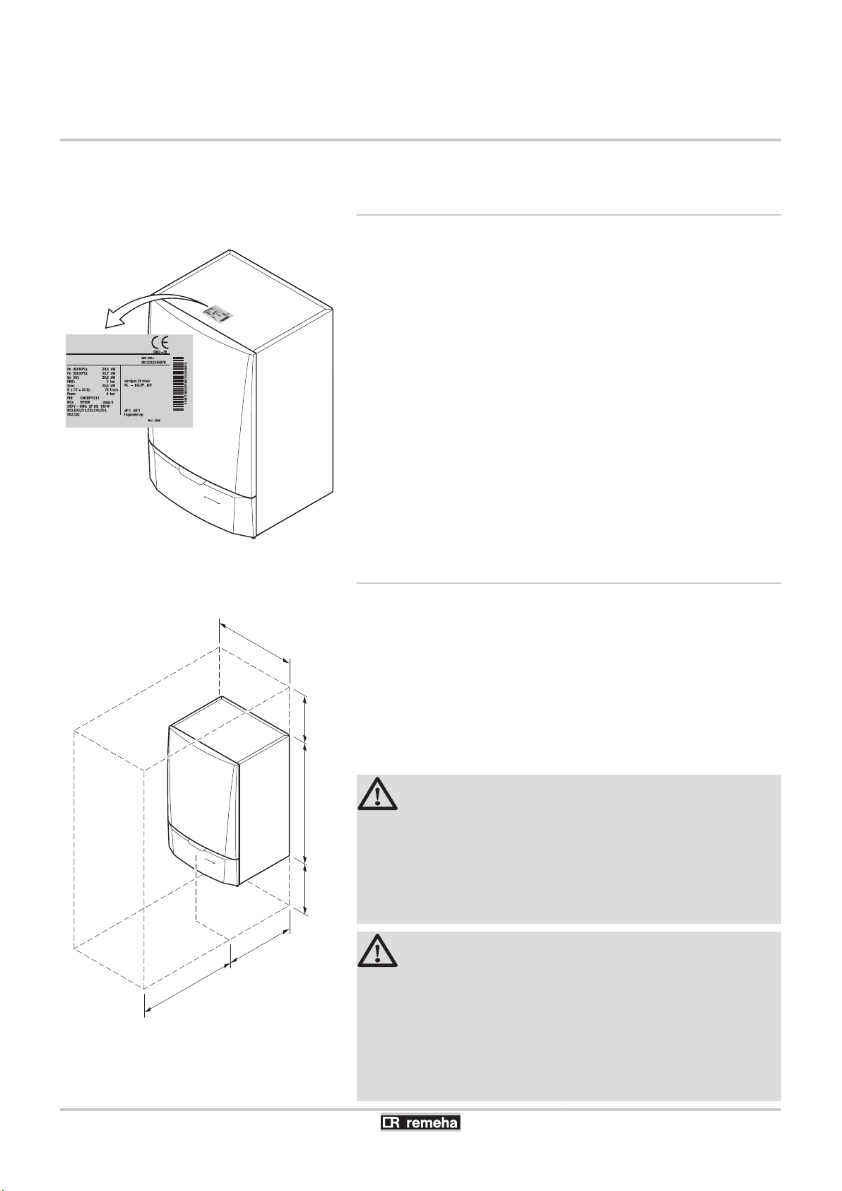
T001539-B
T001531-A
450
min.1000
395
min.
250
min.
250
690
4. Installation Calenta 25s - 28c - 35s - 40c
4.3 Choice of the location
4.3.1. Data plate
The data plate located on top of the boiler provides important
information on the appliance: serial number, model, gas category, etc.
4.3.2. Location of the boiler
4 Before mounting the boiler, decide on the ideal position for
mounting, bearing the Directives and the dimensions of the
appliance in mind.
4 When choosing the position for mounting the boiler, bear in mind
the authorised position of the combustion gas discharge outlets
and the air intake opening.
4 To ensure adequate accessibility to the appliance and facilitate
maintenance, leave enough space around the boiler.
WARNING
4 Fix the appliance to a solid wall capable of bearing
the weight of the appliance when full of water and fully
equipped.
4 It is forbidden to store inflammable products and
materials in the boiler room or close to the boiler,
even temporarily.
CAUTION
4 The boiler must be installed in a frost-free
environment.
4 An earthed wall socket must be available close to the
boiler.
4 A connection to the mains drainage system for the
discharge of condensate must be available close to
the boiler.
22
040412 - 7600585-01
T000756-A
Z
OZ
1
0
B
2 3
60
225
240
T001532-A
min. 550
min.495
min. 250
50 (2)
min. 250
100
min. (1)
Calenta 25s - 28c - 35s - 40c 4. Installation
Safety rating
n
B
Z
OZ
Bathtub or shower tray
Zones
Breakdown of the exterior zone
For safety rating IP X4D, installation in the bathroom is possible in
zones 2 and 3 and in the breakdown of the exterior zone.
4 In this case, connect the 230V power supply as a fixed connection.
4 Also in this case, connect an air intake pipe.
CAUTION
In the case of a fixed connection to the power cord, you
must always install a main bipolar switch with an opening
gap of at least 3 mm (EN 60335-1).
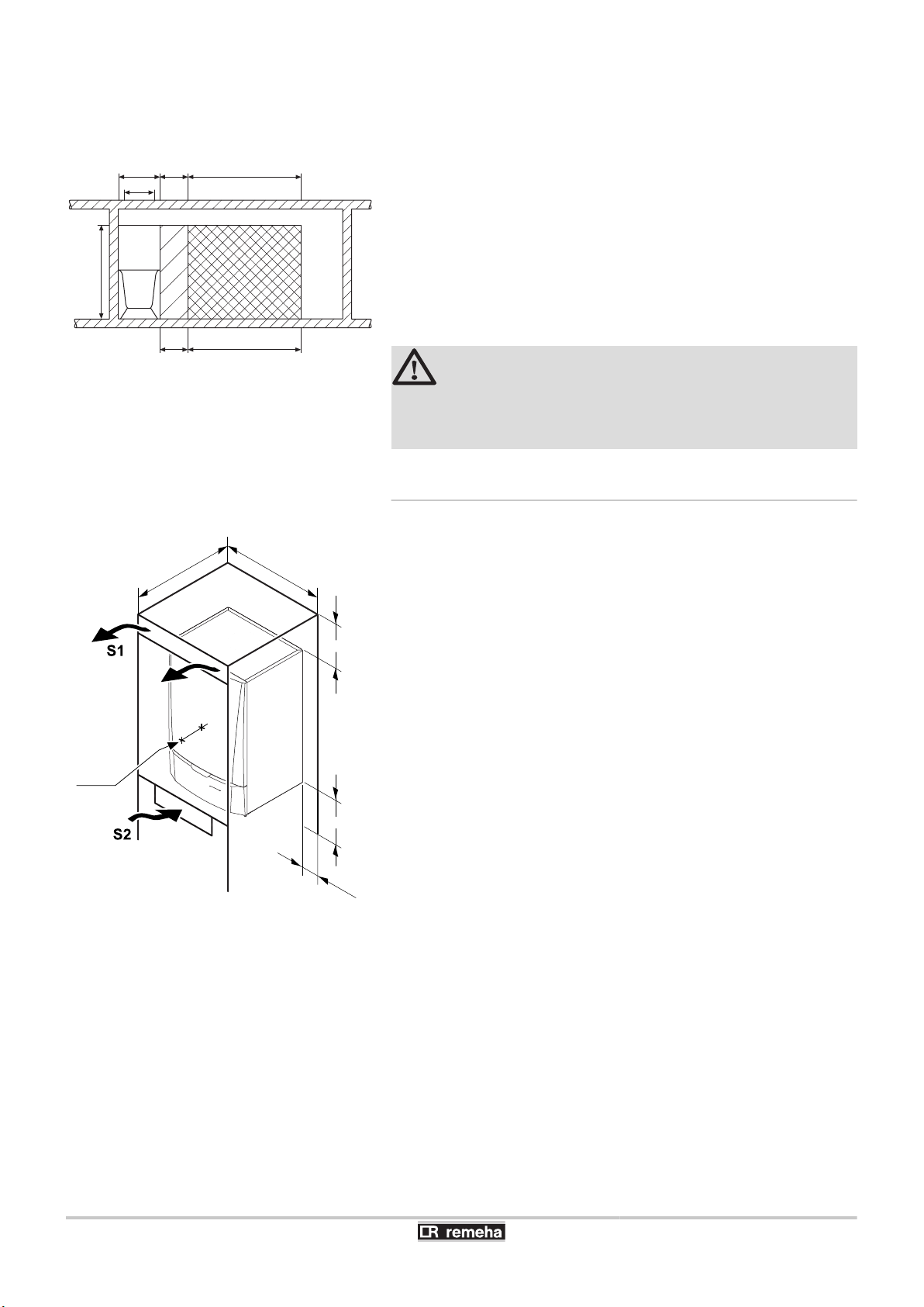
4.3.3. Ventilation
(1)
(2)
Distance between the front of the boiler and the internal
wall of the casing box.
Distance to allow on either side of the boiler.
If the boiler is installed in a closed casing, respect the minimum
dimensions given in the diagram opposite. Also allow openings to
obviate the following hazards:
4 Accumulation of gas
4 Heating of the box
Minimum cross section of the openings: S1 + S2 = 150 cm
2
040412 - 7600585-01
23
T000754-C
67
195
265
132
199
266
331
690
450
395
225
120
140
140
150
257,5
67
195
265
132
199
266
331
690
450
395
225
120
140
140
150
257,5
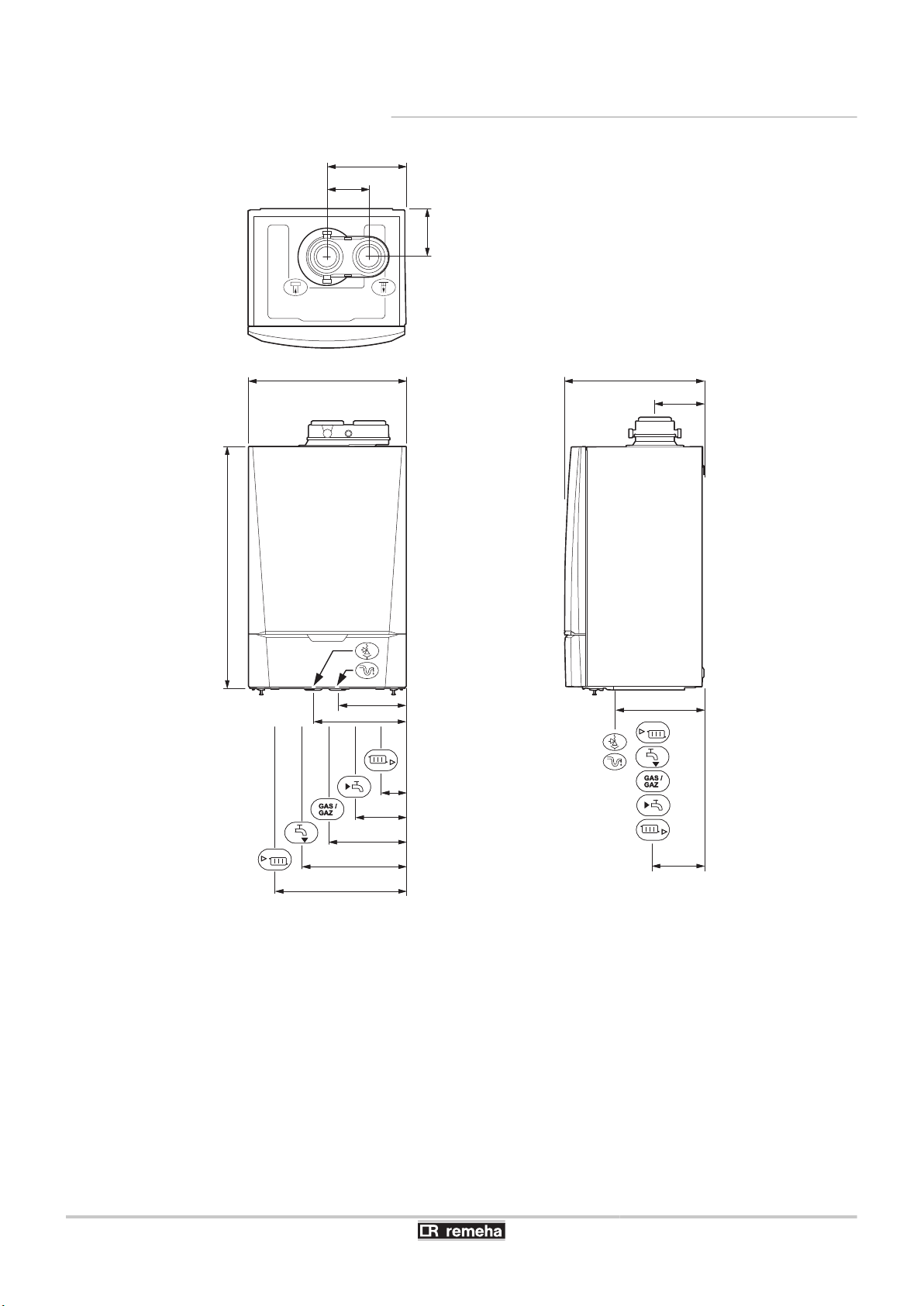
4. Installation Calenta 25s - 28c - 35s - 40c
4.3.4. Main dimensions
i
h
ê
j
z
x
Gas /
Gaz
Connection of the combustion gas exhaust pipe; Ø 80 mm
Connection of the air intake pipe; Ø 80 mm
Safety valve outlet pipe; Ø 25 mm
Condensates discharge; Ø 25 mm
Heating circuit return; Clamping Ø 22 mm
Domestic cold water inlet; Clamping Ø 15 mm
Gas connection; Clamping Ø 15 mm
24
y
{
Domestic hot water outlet; Clamping Ø 15 mm
Heating circuit flow; Clamping Ø 22 mm
040412 - 7600585-01
T001540-A
2
1
5
4
3
Calenta 25s - 28c - 35s - 40c 4. Installation
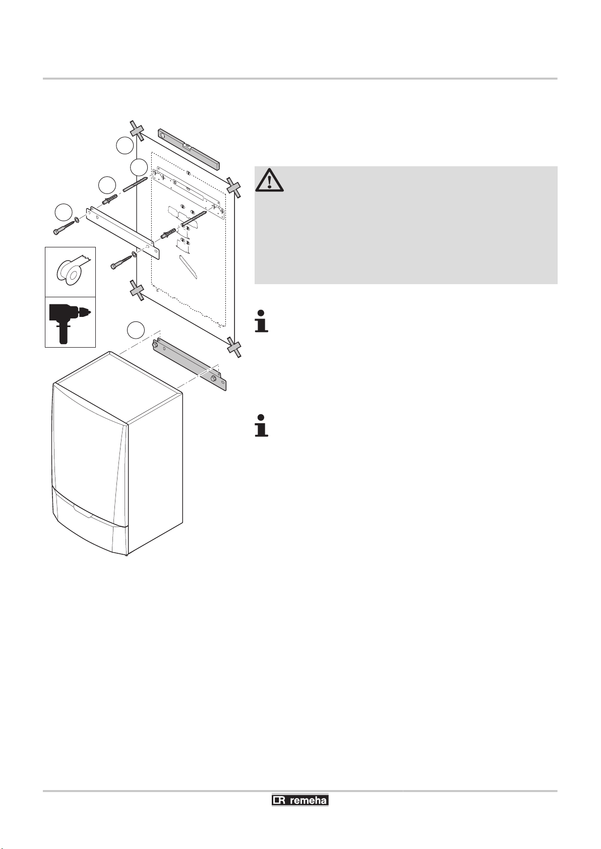
4.4 Positioning the boiler
The boiler is delivered with a mounting template.
A suspension clamp situated at the rear of the casing enables the
boiler to be directly suspended on the mounting bracket.
1. Position the mounting template to the wall with adhesive tape.
CAUTION
4 Using a spirit level, check that the mounting axis is
perfectly horizontal.
4 During mounting, cover up the connection points for
the air supply and the combustion gas exhaust, to
protect the boiler and its connections from dust. Only
remove this protection at the time when these
connections are made.
2. Drill 2 holes with a Ø of 10 mm.
Additional holes are provided in case one or other of the
standard locating holes prevents the correct location of the
plugs.
3. Insert the rawplugs with a Ø of 10 mm.
4. Attach the mounting bracket to the wall with the provided bolts with
a Ø of 10 mm.
5. Hang the boiler on the mounting bracket.
The relevant assembly instruction describes how to hang
the mounting frame (accessory).
040412 - 7600585-01
25
T001535-C
1
2
3
7
5
6
4
T001534-C
1
2
3
4
5
8
6
7
4. Installation Calenta 25s - 28c - 35s - 40c
4.5 Alternatives for hydraulic connections
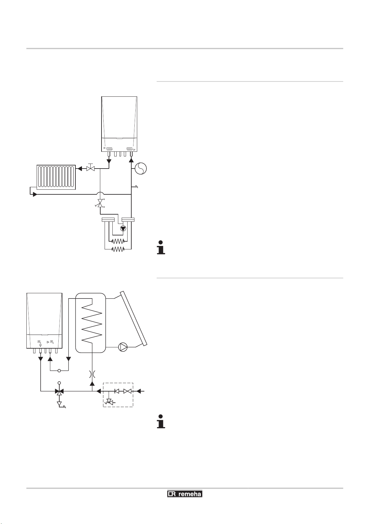
4.5.1. Connection of the underfloor heating
1
2
3
4
5
6
7
Boiler
Expansion vessel
Stopcock
Regulator valve
Filling/drainage valve
Underfloor heating
Heating by radiators
The boiler can be connected directly to an underfloor heating circuit.
If using plastic ducting (for the underfloor heating for example), the
plastic tubes must be totally oxygen-tight according to standard DIN
4726/4729. If the synthetic ducting used in the installation does not
conform to these standards, it is advisable to hydraulically separate
the boiler circuit from the central heating circuit by installing a plate
heat exchanger.
Parameters p"8 and p"9 are used to modify the
pump settings.
4.5.2. Connection of a solar hot water tank
1
2
3
4
5
6
7
8
Boilers, of the heating and domestic hot water production type, are
Boiler
Tank
Solar collector
Pump
Flow limiter
Safety unit
Mixer valve
Solar DHW sensor SCU-S02
suitable for reheating downstream from solar DHW tanks. A kit
(accessory) is available for the connection.
See the solar domestic hot water tank's technical notes for
more information concerning hydraulic connections.
26
040412 - 7600585-01
T004865-A
1
2
4
6
7
M
3
5
8
Calenta 25s - 28c - 35s - 40c 4. Installation
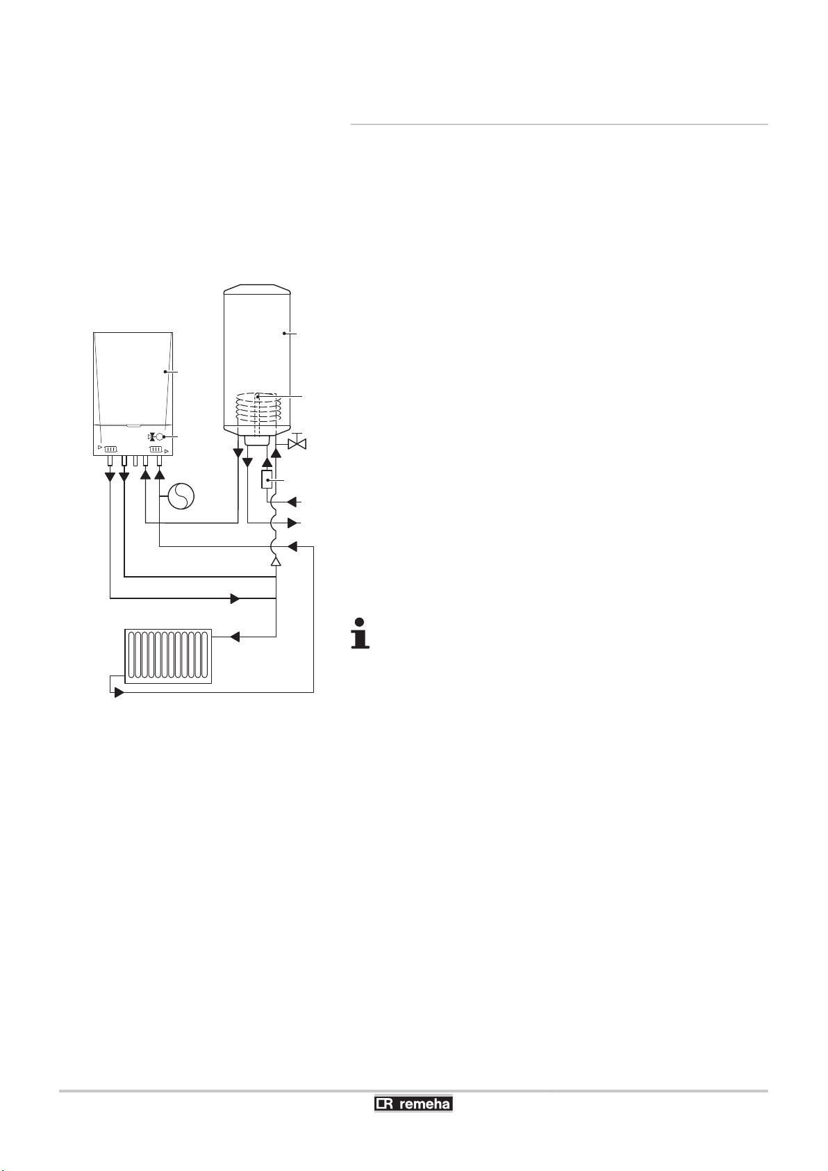
4.5.3. Connection of an independent hot water
tank
The standard version of the heating-only type of boiler is fitted with a
command for regulation of the hot water tank circuit. The command
is adjusted to switch preferentially to the hot water tank circuit. This
gives priority to the hot water tank when simultaneous requests for
heat come from the hot water tank and the central heating. The
indirectly heated calorifier can be connected using an internal or
external three-way valve.
Internal three-way valve
1
2
3
4
5
6
7
8
Boiler
Independent hot water tank
DHW sensor
Air vent kit of the hot water tank
Safety unit
Expansion vessel
Heating-Installation
3-way valve
The boiler connection kit must be used to install the three-way valve
in the boiler (Accessory). The three-way valve (230 V) is controlled
by the boiler control unit of the boiler.
¼ For the installation or mounting of any accessories, refer to the
mounting instructions delivered with the accessories in question.
4
A safety unit is installed at the point where cold water
arrives at the hot water tank to prevent backflow or
overpressure.
4 The central heating pipes for the boiler circuit must be
in Ø 22 mm (From Ø 15 mm to Ø 22 mm at the boiler
itself).
040412 - 7600585-01
27
T001537-C
1
2
4
8
6
7
M
3
5
9
T001536-B
1
2
3
4. Installation Calenta 25s - 28c - 35s - 40c
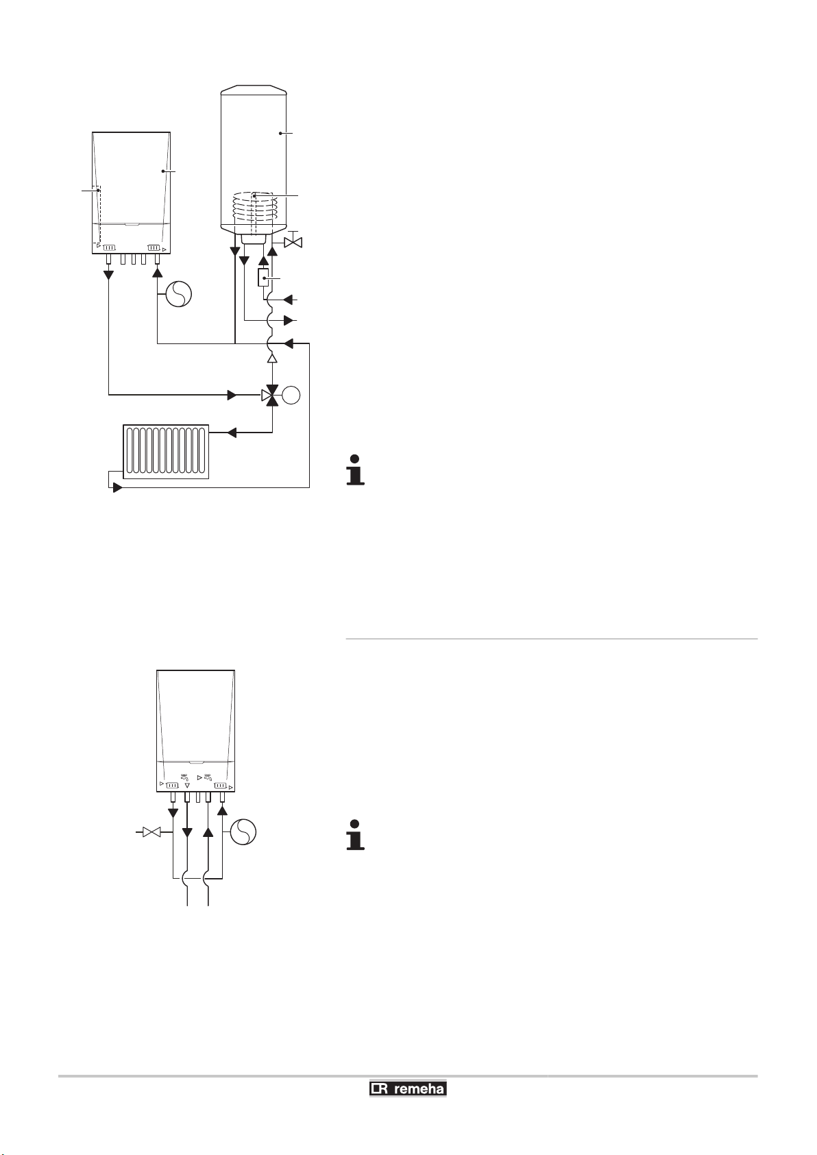
External three-way valve
1
2
3
4
5
6
7
8
9
Boiler
Independent hot water tank
DHW sensor
Air vent kit of the hot water tank
Safety unit
Expansion vessel
Heating-Installation
3-way valve
SCU-X02 control PCB
Control SCU-X02 must be used to install the three-way valve outside
of the boiler (Accessory). The three-way valve 24 V/230 V is
controlled by control SCU-X02. The control must be installed in the
electronics expansion kit (Accessory).
¼ For the installation or mounting of any accessories, refer to the
mounting instructions delivered with the accessories in question.
4 In order to prevent an uncontrolled flow in the heating
circuit, the return channel to the hot water tank must
always be connected directly to the return channel to
the boiler and therefore never directly connected to
the heating installation.
4 A safety unit is installed at the point where cold water
arrives at the hot water tank to prevent backflow or
overpressure.
4.5.4. Geyser use
1
2
3
The combi boiler can also be used solely for DHW operation. The
boiler can then function as a geyser. The central heating function has
to be switched off for this purpose, using parameter p3.
Boiler
Filling/drainage valve
Expansion vessel
The flow and return connections of the unit have to be
connected.
28
040412 - 7600585-01

T001958-A
1
2
3
5
4
Calenta 25s - 28c - 35s - 40c 4. Installation
4.5.5. Solo use
4.6 Hydraulic connections
1
2
3
4
5
Boiler
Expansion vessel
Stopcock
Filling/drainage valve
Heating by radiators
The combi boiler can also be used solely for central heating
operation. The hot water function has to be switched off for this
purpose, using parameter p3.
The sanitary pipes do not have to be connected or capped
off. The dust caps supplied are sufficient.
4.6.1. Flushing the system
Installing the boiler in new installations (installations less than
6 months old)
4 Clean the installation with a universal cleaner to eliminate debris
from the appliance (copper, hemp, flux).
4 Thoroughly flush the installation until the water runs clear and
shows no impurities.
Installing the boiler in existing installations
4 Remove sludge from the installation.
4 Flush the installation.
4 Clean the installation with a universal cleaner to eliminate debris
from the appliance (copper, hemp, flux).
4 Thoroughly flush the installation until the water runs clear and
shows no impurities.
040412 - 7600585-01
29

T001573-C
T001570-B
T001633-B
4. Installation
Calenta 25s - 28c - 35s - 40c
4.6.2. Connection of the heating circuit
1. Remove the anti-dust plug located on the heating outlet
connection { under the boiler.
2. Connect the heating water outlet pipe to the heating flow
connection.
3. Install a filling and drainage valve on the installation for filling and
draining the boiler.
4. Remove the anti-dust plug located on the heating return
connection z under the boiler.
5. Connect the heating water return pipe to the heating return
connection.
4 The boiler is factory fitted with a safety valve mounted
on the left hydroblock.
4 To facilitate maintenance work, we recommend
mounting a shut off valve on the heating flow and
return pipes.
CAUTION
4 The heating pipe must be mounted in accordance
with prevailing provisions.
4 If installing shut off valves, position the filling/
drainage valve and the expansion vessel between
the shut off valves and the boiler.
¼ If using thermostatic valves, see chapter: "Connecting the
expansion vessel", page 31
30
040412 - 7600585-01

T001572-B
T001571-C
Calenta 25s - 28c - 35s - 40c 4. Installation
4.6.3. Hydraulic connection of the water circuit
for domestic use
1. Remove the anti-dust plug located on the domestic cold water
connection x under the boiler.
2. Remove the anti-dust plug located on the domestic hot water
connection y under the boiler.
3. Connect the cold water inlet pipe to the domestic cold water
connection. Install a safety unit labelled KIWA on this pipe directly
under the boiler.
4. Place a tube, connected to the drains, underneath the safety unit
for water from expansion.
5. Connect the domestic hot water outlet pipe to the domestic hot
water connection.
CAUTION
4 The domestic water pipes must be connected in
accordance with prevailing provisions.
4 If using synthetic pipes, follow the manufacturer's
(connection) instructions.
4.6.4. Connecting the expansion vessel
Install the expansion vessel on the heating return pipe z.
If using a heating and domestic hot water production type
boiler on an installation in which the flow can be fully
disconnected from the return (e.g. by using thermostatic
valves), you should either fit a bypass or fit an expansion
vessel to the heating flow conduit.
4.6.5. Connecting the condensate discharge pipe
1. Mount a standard drainage pipe, Ø 32 mm or more, leading to the
mains drainage system.
2. Into this, insert the condensate collector hose coming from the
siphon j and the safety valve ê.
3. Mount a trap or a siphon in the discharge pipe.
CAUTION
Do not make a fixed connection owing to maintenance
work on the siphon.
040412 - 7600585-01
4 Do not plug the condensate discharge pipe.
4 Set the discharge pipe at a gradient of at least 30 mm
per metre, maximum horizontal length 5 metres.
4 Do not drain condensation water into a roof gutter at
any time.
4 Connect the condensate discharge pipe in
accordance with prevailing standards.
31
T001575-B
4. Installation Calenta 25s - 28c - 35s - 40c
4.7 Gas connection
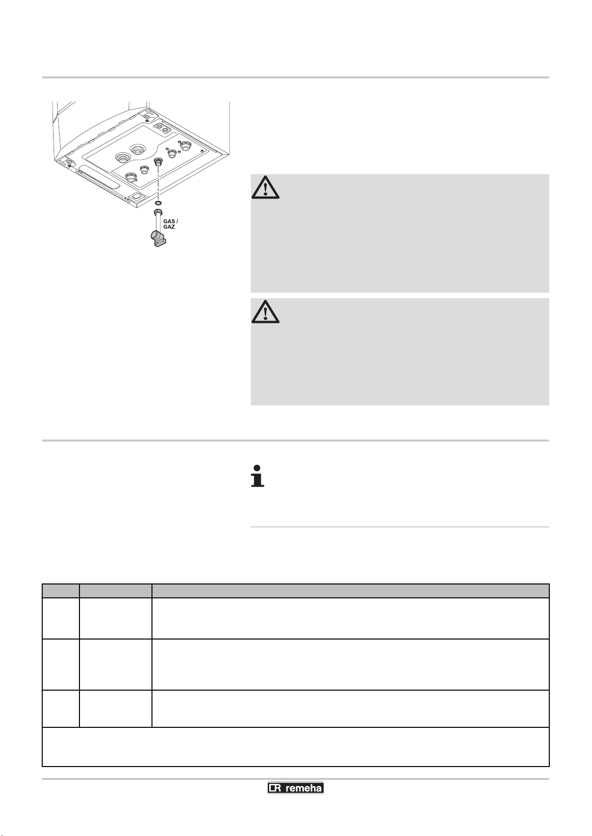
1. Remove the anti-dust plug located on the gas connection GAS/
GAZ under the boiler.
2. Connect the gas inlet pipe.
3. Mount a gas isolation valve on this pipe, directly under the boiler.
4. Connect the gas pipe to the gas shut off valve.
WARNING
4 Close the main gas valve before starting work on the
gas pipes.
4 Before mounting, check that the gas meter has
sufficient capacity. To do this, you should keep in
mind the consumption of all domestic appliances.
4 If the gas meter has too low a capacity, inform the
energy supply company.
CAUTION
4 Ensure that there is no dust in the gas pipe. Blow into
the pipe or shake it before mounting.
4 We recommend installing a gas filter on the gas pipe
to prevent clogging of the gas valve unit.
4 Connect the gas pipe in accordance with prevailing
standards and regulations.
4.8 Connections for the air and exhaust pipes
¼ The boiler is suitable for the following types of flue
gas connections. See chapter: "Certifications", page 7
4.8.1. Classification
The table specifies this classification in detail according to [.
Type
B23
B23P
B33 Open
C13 Closed
(1) Including the pressure classification P1
(2) EN483: 0,5 mbar suction by pressure reduction
(3) An under pressure of 4 mbar is possible
(4) See table for minimum sizes of duct or sleeving
Execution Description
Open
(1)
4 Without fire-stop approval.
4 Exhaust of combustion gases above the roof.
4 Air in the installation room.
4 Without fire-stop approval.
4 Common exhaust of combustion gases above the roof.
4 Common exhaust of combustion gases mixed in the air, air in the installation room (special
4 Vent in the outside wall.
4 The opening for the air-supply inlet is located in the same pressure zone as the vent (For
construction).
example, a common passage through the outside wall).
32
040412 - 7600585-01

Calenta 25s - 28c - 35s - 40c
Type Execution Description
C33 Closed
(2)
C43
C53 Closed
C63 Closed
C83
C93
(1) Including the pressure classification P1
(2) EN483: 0,5 mbar suction by pressure reduction
(3) An under pressure of 4 mbar is possible
(4) See table for minimum sizes of duct or sleeving
Closed/Cascade
(3)
Closed
(4)
Closed
4 Exhaust of combustion gases above the roof.
4 The opening for the air-supply inlet is located in the same pressure zone as the vent (For
example, a concentric passage to the roof).
4 Common channelling for the air-supply and exhaust of combustion gases (CLV):
- Concentric.
- Eccentric; Air supply from the shaft.
4 This also relates to the overpressure cascades.
4 Closed equipment.
4 Separate channelling for the air-supply.
4 Separate channelling for the combustion gases.
4 Terminating on different pressure surfaces.
4 The manufacturer delivers this type of equipment without a supply or exhaust system.
4 The equipment can be connected on a so-called semi-CLV system (with common combustion
gas exhaust).
4 Channel for the air-supply and exhaust fumes in a duct or surrounded by a sleeve:
- Concentric.
- Eccentric; Air supply from the shaft.
- Exhaust of combustion gases above the roof.
- The opening for the air-supply inlet is located in the same pressure zone as the vent.
4. Installation
Type Execution Diameter Minimum size of the duct or jacket.
Without air-supply With air-supply
∅ Channel Channel ∅ Channel Channel
C93 Rigid 60 mm 110 mm 110 x 110 mm 120 mm 110 x 110 mm
80 mm 130 mm 130 x 130 mm 140 mm 130 x 130 mm
100 mm 160 mm 160 x 160 mm 170 mm 160 x 160 mm
Flexible 60 mm 110 mm 110 x 110 mm 120 mm 110 x 110 mm
80 mm 130 mm 130 x 130 mm 145 mm 130 x 130 mm
100 mm 160 mm 160 x 160 mm 170 mm 160 x 160 mm
Concentric 60/100 mm 120 mm 120 x 120 mm 120 mm 120 x 120 mm
80/125 mm 145 mm 145 x 145 mm 145 mm 145 x 145 mm
100/150 mm 170 mm 170 x 170 mm 170 mm 170 x 170 mm
4.8.2. Outlets
in general, it is possible to use a standard kit for passage via the roof
or outside wall. In the case of such passage via the outside wall
directly above the boiler, use the Remeha kit for passage via an
outside wall. This is available as an accessory.
For exhausting combustion gases of types C1, C3 and C5, it is
appropriate to use a M&G Skyline / Mugro 3000 or a Coxstand E
HR. When exhausting combustion gases of type C6, the material of
the exhaust must conform with Gastec QA and/or be provided with
CE marking.
040412 - 7600585-01
The exhaust vent for combustion gases must conform to EN
1856-1. The flue gas pipes must be calculated conforming to EN
13384 (parts 1 & 2).
33

T000765-B
L
4. Installation Calenta 25s - 28c - 35s - 40c
For open exhaust of combustion gases above the roof, the
vent must always be provided with a suitable stainless steel
wire grill.
4.8.3. Lengths of the air/flue gas pipes
4 To define the maximum final length, you must deduct
the pipe length in accordance with the reduction table.
4 The boiler is also suitable for longer chimney lengths
with diameters other than those indicated in the
table. Please contact us for further information.
Open flue (B23, B23P, B33)
n
If using an open flue version, the air supply opening remains open;
only the combustion gas opening is connected. The boiler then takes
in the combustion air required directly from the premises in which it
is installed. For the application of air discharge and combustion gas
discharge piping with a diameter other than 80 mm, a reducer should
be used.
CAUTION
4 The air supply opening must remain open.
4 The premises in which the appliance is installed must
be fitted with the necessary air supply openings.
They must not be reduced or closed.
Chimney length for the open flue version
Situation Diameter
60 mm 19 m 16 m 11 m 10 m
Free vent in zone I
Restricted vent in
zone III
Countryside (ΔP
static = + 25 Pa)
Restricted vent in
zone III Near the
coast (ΔP static =
+ 40 Pa)
70 mm 35 m 30 m 21 m 19 m
80 mm 40 m 40 m 40 m 40 m
90 mm 40 m 40 m 40 m 40 m
60 mm 15 m 13 m 9 m 9 m
70 mm 28 m 24 m 17 m 16 m
80 mm 40 m 40 m 40 m 39 m
90 mm 40 m 40 m 40 m 40 m
60 mm 12 m 11 m 8 m 8 m
70 mm 23 m 21 m 14 m 14 m
80 mm 40 m 40 m 35 m 35 m
90 mm 40 m 40 m 40 m 40 m
Calenta
25s
Maximum length (L)
Calenta
28c
Calenta
35s
Calenta
40c
34
040412 - 7600585-01

T000766-B
L
T000780-C
L
Calenta 25s - 28c - 35s - 40c 4. Installation
Room sealed flue (C13, C33, C43, C63, C93)
n
If using a room sealed version, it is necessary to connect both the
combustion gas exhaust and the air-supply opening (parallel). For the
application of air discharge and combustion gas discharge piping with
a diameter other than 80 mm, a reducer should be used.
Chimney length for room sealed operation
Maximum length (L)
Situation Diameter
Free vent in
zone I or
Restricted vent
in zone III
60-60 mm 7 m 5 m - -
70-70 mm 18 m 15 m 9 m 8 m
80-80 mm 20 m 20 m 20 m 19 m
90-90 mm 20 m 20 m 20 m 20 m
Calenta
25s
Calenta
28c
Calenta
35s
Calenta
40c
Connection in areas of different pressure (C53, C83)
n
Combustion air supply and combustion gas discharge are possible in
various pressure zones, semi-CLV systems. With the exception of
coastal areas. The maximum permissible difference in height
between the combustion air supply and the combustion gas discharge
is 36 m.
Chimney length in the various pressure zones
Maximum length (L)
Situation Diameter
70 mm 13 m 13 m 5 m 5 m
Free vent in
zone I
Reduction table
n
Pipe reductions per element used
Diameter
60 mm 0,9 m 3,1 m
70 mm 1,1 m 3,5 m
80 mm 1,2 m 4,0 m
90 mm 1,3 m 4,5 m
100 mm 1,4 m 4,9 m
80 mm 36 m 36 m 24 m 23 m
90 mm 36 m 36 m 36 m 36 m
100 mm 30 m 36 m 36 m 36 m
Elbow 45° Elbow 90°
Pipe reduction Pipe reduction
Calenta
25s
Calenta
28c
Calenta
35s
Calenta
40c
040412 - 7600585-01
35

4. Installation
Calenta 25s - 28c - 35s - 40c
4.8.4. Specific air/flue gas applications
If the boiler has been modified, for example:
4 high pressure systems
4 WTW coupling
4 CLV overpressure (combusted gas discharge
systems)
It is necessary to mention on the sticker provided: This
boiler has been set for.... This sticker must be affixed to the
top of the boiler next to the identification plate.
4 Please contact us for further information.
high pressure systems
n
Flue gas discharge hoses with smaller diameters are available
commercially for use with the boiler, these hoses are specifically for
renovations where the existing flue gas discharge duct is not suitable
for condensing flue gases.. Some boiler settings must be changed for
this application of the boiler.
This is described in detail in the flue gas discharge systems
practical manual Calenta.
WTW coupling
n
The boiler has been prepared for use in conjunction with a Itho
HRU heat exchanger unit. Some boiler settings must be changed for
this application of the boiler. Full details are provided with the special
connection kit (accessory component).
Always use the heat exchanger connection kit when using
the heat exchanger coupling.
CLV overpressure (combusted gas discharge systems)
n
Under certain conditions, the boiler can be used in a CLV
overpressure system. Some boiler settings must be changed for this
application of the boiler. The setting can be modified using
parameters p19 and p"0.
¼ See chapter: "Changing the settings", page 64
36
4.8.5. Additional Directives
4 Please refer to the manufacturer's instructions for the material in
question when installing the flue gas discharge and air supply
materials. If the flue gas discharge and air supply materials are not
installed according to the instructions (e.g. they are not leakproof,
not clamped in place etc.), this may cause hazardous situations
and/or result in bodily injury. After assembly, check at least all flue
gas and air–carrying parts for tightness.
040412 - 7600585-01

T001972-A
Calenta 25s - 28c - 35s - 40c 4. Installation
4 Connection of the combustion gas exhaust directly to the buildings
brick chimneys or flues is forbidden for condensation reasons.
4 If flues or chimneys are to be used, they must have an airtight
construction with thick walls and be made from rigid aluminium or
stainless steel. Flexible supply flue pipes made from plastic or
stainless steel are also permissible. Aluminium is permissible only
if there is no contact between the building supply section and the
combustion gas exhaust pipe.
4 Always clean the ducts thoroughly in cases where lining pipes are
used and/or a connection of the air-supply.
It must be possible to inspect the flue or chimney.
4
4 In cases where condensate coming from the stainless steel or
plastic sections of the flue gas pipe can be driven back towards
the aluminium section, this condensate must be removed using a
collecting device before the aluminium section is reached
(conforming with NPR 3378).
4 For long, aluminium, combustion-gas exhaust pipes it is initially
necessary to consider the relatively high quantity of corrosive
products which are brought together with the condensate from the
exhaust pipe. The siphon on the equipment requires regular
cleaning or, preferably, an additional condensate collector can be
installed above the equipment.
4 The combusted gas discharge pipe must be sufficiently inclined
towards the boiler (at least 50 mm per metre) and an adequate
condensate collection tank and discharge system constructed (at
least 1 m before the boiler opening). The elbows fitted must be at
more than 90° to guarantee the provision of an adequate gradient
and tightness on the lip rings.
Please contact us for further information.
4.8.6. Air/Exhaust adapter
The boiler is factory fitted with a two pipe connection. During
installation, the room ventilated or room sealed version can be
selected. Where needed, the outlet of the combustion gas / air supply
can be turned through 180º. The air supply will then be located to the
left of the combustion gas outlet and not to the right.
040412 - 7600585-01
37

T001512-A
80mm
S
T001513-A
80mm
S
4. Installation Calenta 25s - 28c - 35s - 40c
4.8.7. Connection of the combustion gas exhaust
pipe
S
Insertion depth 3 cm
Mounting
1. Fit the combustion product discharge conduit.
2. Fit together the combustion gas exhaust pipes, without welding.
4 The pipes must allow no leakage of flue gases and be
resistant to corrosion.
4 Connect the pipes together without stress between
the sections.
4 The horizontal sections need to be constructed with a
gradient of 50 mm per metre: Boiler orientation.
Material
Thick aluminium wall Approval according to EN-1856-1
Stainless steel Approval according to EN-1856-1
A rigid wall
Flexible
(1) The sealing must conform with pressure class 1
(1)
Synthetic material T120 Approval according to Gastec
QA or KOMO
Stainless steel Approval according to EN-1856-1
(1)
Synthetic material T120 Approval according to Gastec
QA or KOMO
4.8.8. Connection of the air intake pipe
S
Mounting
1. Fit the air-intake conduit.
2. Fit the air-intake conduits together without welding.
Material
A rigid wall
Flexible
Insertion depth 3 cm
The pipes must allow no leakage of flue gases and be
4
resistant to corrosion.
4 Connect the pipes together without stress between
the sections.
4 The horizontal sections need to be constructed with a
gradient: Downwards in the direction of the supply
opening.
aluminium/Stainless steel/Synthetic material
38
040412 - 7600585-01

Calenta 25s - 28c - 35s - 40c
4.9 Electrical connections
4. Installation
4.9.1. Control unit
The boiler is not line- and neutral sensitive. The boiler is fully prewired. All external connections can be made on the connection
connector (low voltage). The main characteristics of the control unit
are described in the table below.
Power supply voltage 230 VAC/50Hz
Rating of the main fuse F1 (230 VAC) 6.3 AT
Fuse rating F2 (230 VAC) 2 AT
Fan-DC 27 VDC
CAUTION
The following boiler components are at a voltage of
230V:
4 Electrical connection of the heating pump (Central
heating) (if used).
4 Electrical connection of the combined gas valve unit.
4 Electrical connection of the 3-way valve (if used).
4 The majority of components in the control panel.
4 Ignition transformer.
4 Connection of the power supply cable.
The boiler is fitted with an earthed plug (cable length 1,5 m) suitable
for a 230VAC/50Hz power supply with live/neutral/earth system. The
power supply cable is connected to the X1 connector. A spare fuse
can be found in the housing of the control system.
CAUTION
4 When the power supply cable has to be replaced, it
must be ordered from Remeha.
4 The boiler plug must be accessible at all times.
It is possible to connect various control, safety and regulation systems
to the boiler. The standard control PCB (PCU) can be extended with
the following, for example:
4 The 0-10V control PCB (accessory IF-01). For installation behind
the left hand cover on the control panel.
4 The extended control PCB (accessory SCU-S02). For installation
in a box (accessory).
¼ For the optional PCBs, see chapter: "Optional electrical
connections", page 46
040412 - 7600585-01
39

4. Installation Calenta 25s - 28c - 35s - 40c
4.9.2. Recommendations
WARNING
4 Only qualified professionnals may carry out electrical
connections, always with the power off.
4 The boiler is entirely pre-wired. Do not modify the
connections inside the control panel.
4 Earth the appliance before making any electrical
connections.
Make the electrical connections of the boiler according to:
4 The instructions of the prevailing standards.
4 The instructions on the electrical diagrams provided with the
boiler.
4 The recommendations in the instructions.
CAUTION
Separate the sensor cables from the 230 V cables.
40
040412 - 7600585-01

R000073-A
OT
On/
off
Tout
T
dh
w
BL
RL
X13
X12
7
4
4
3 3
3
1
90º
1
Calenta 25s - 28c - 35s - 40c 4. Installation
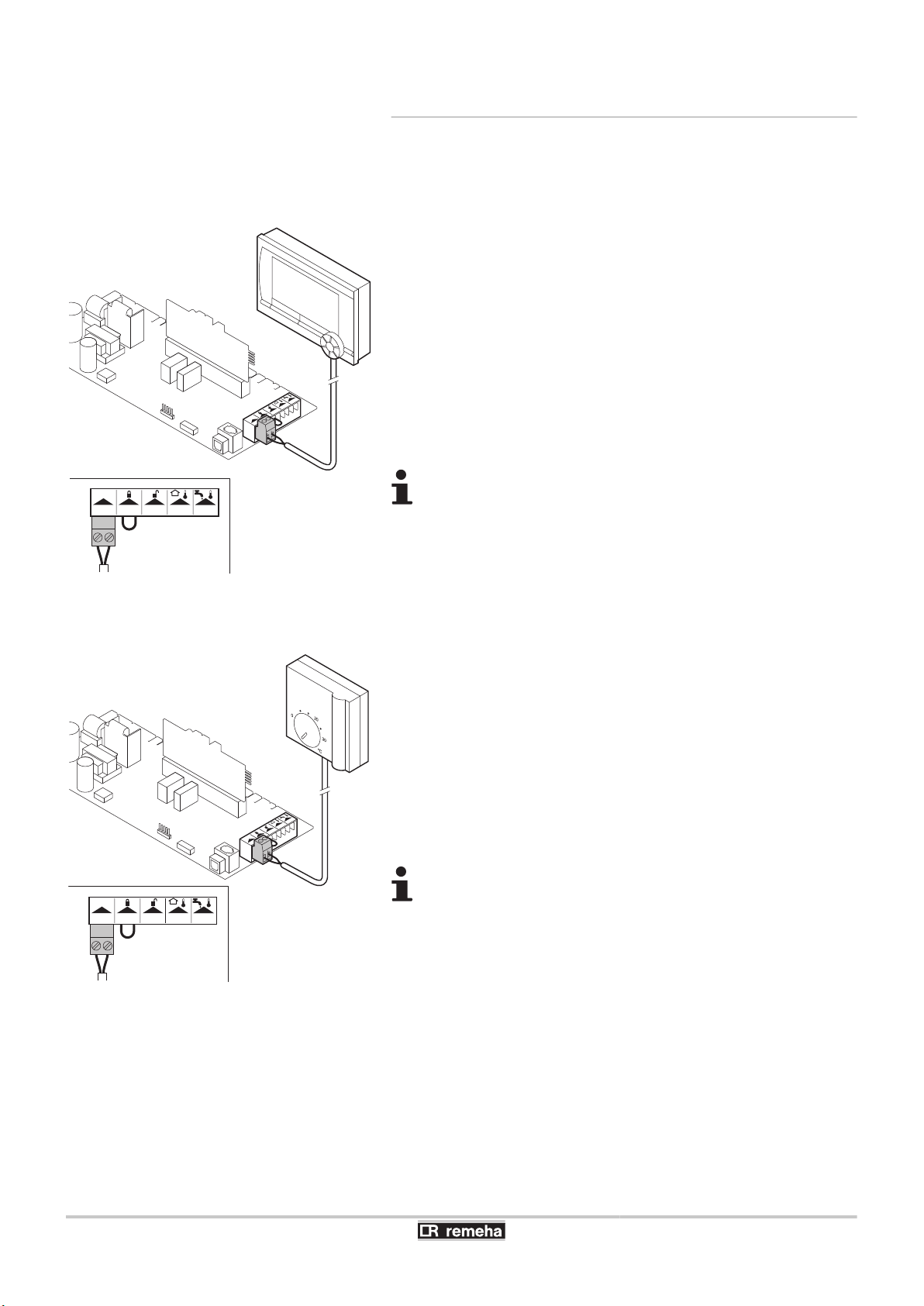
4.9.3. Standard control PCB
Various thermostats and controllers can be connected to the standard
control PCB (PCU) (X12 connector block). The possible connections
on the standard control PCB are described in the following
paragraphs.
Access to the connector block:
1. Unscrew the two screws located under the front panel by a quarter
turn and remove the panel.
2. Thread the cables from the regulator or thermostat through the
right-hand grommet(s) on the lower plate of the boiler.
3. Tilt the control box forwards by opening the holding clips located
at the sides.
4. Open the tooling box by opening the clip fastener on the front side.
5. Run the connection cable(s) through the grommet(s) in the control
unit box.
6. Unscrew the necessary cable clamps (to access the connector
block) and introduce the cables.
7. Connect the cables to the appropriate terminals on the connector
block.
8. Firmly retighten the cable clamps and close the control panel.
040412 - 7600585-01
41
T000776-D
On/off
OT BL RL Tou t Tdhw
OT
On/off
Tou
t
Tdhw
BL
RL
OT
T001590-B
Tk
OT
On/off
Tou
t
Tdhw
BL
RL
On/off
OT BL RL Tou t Tdhw
4. Installation Calenta 25s - 28c - 35s - 40c
4.9.4. Connecting the room thermostat
Connecting modulating controller
n
OT
OpenTherm regulator
The boiler is fitted with a OpenTherm connection as standard.
As a result, modulating OpenTherm room controllers can be
connected without any further adjustments. The boiler is also suitable
for OpenTherm Smart Power.
4 Install the regulator in the reference room (generally the living
room).
4 Connect the two-wire cable to terminals On/off-OT of the
connector.
If the tap water temperature can be set on the
OpenTherm controller, then the boiler supplies this
temperature, with the set value on the boiler as the
maximum.
Connect on/off thermostat
n
Tk
ON/OFF room thermostat
The boiler is suitable for connection to a 2 wire on/off room thermostat.
4 Install the regulator in the reference room (generally the living
room).
4 Connect the 2 wire 24V room thermostat to the On/off-OT
terminals of the connector.
4 Connect the power stealing thermostat to the On/off-OT terminals
of the connector.
If a room thermostat with an anticipation element is used,
this must be converted using parameter p5.
42
040412 - 7600585-01
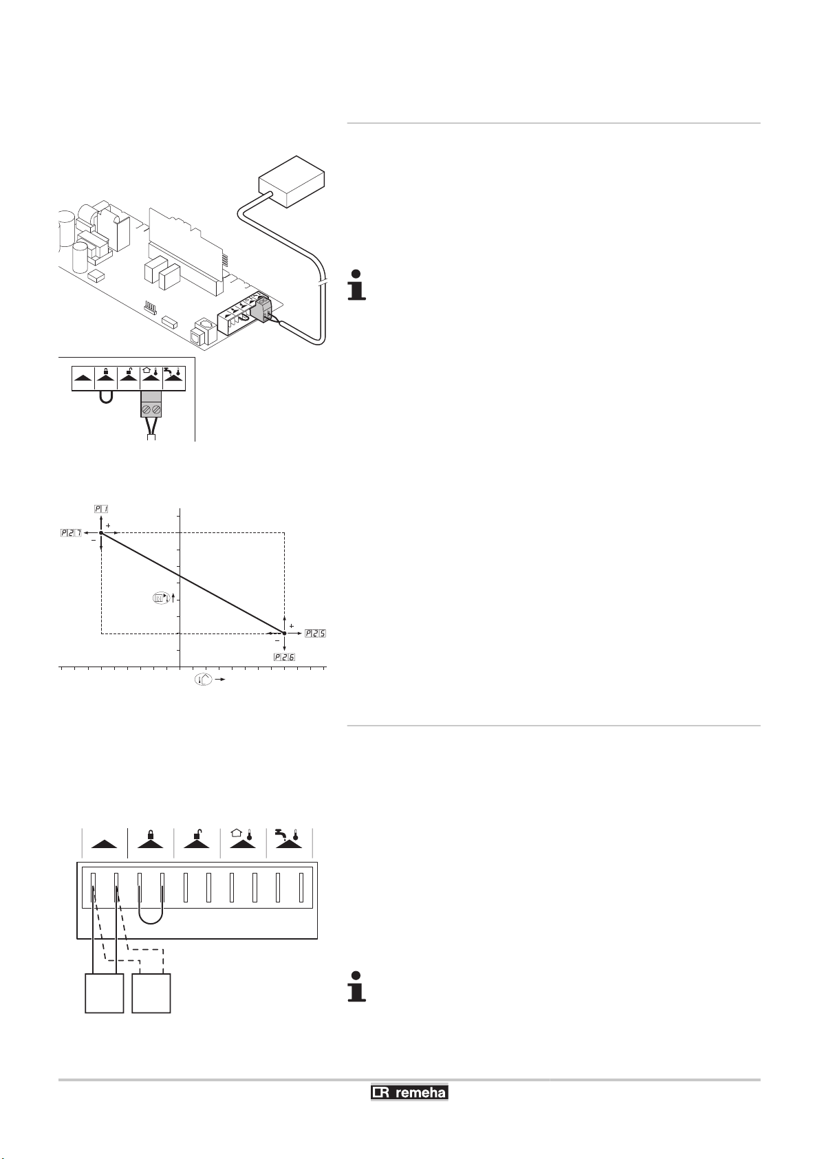
T001591-B
Ba
OT
On/off
Tout
Tdhw
BL
RL
On/off
OT BL RL Tou t Tdhw
R000038-A
0 10 20
-20
-10
10
30
70
50
90
F
T000778-C
On/off
OT RLBL Tou t Tdhw
Tk Tv
Calenta 25s - 28c - 35s - 40c 4. Installation
4.9.5. Connecting the outside temperature
sensor
Ba
Outside sensor
An outside sensor can be connected to the Tout terminals of the
connector. Where there is an on/off thermostat controller, the boiler
will control the temperature with the set point of the internal heating
curve.
A OpenTherm controller can also use this outside sensor.
The heating curve required must then be set on the
controller.
Heating curve setting
n
If an outside temperature sensor is connected, it is possible to adapt
the heating curve. The setting can be modified using parameters
p1, p"5, p"6 and p"7.
040412 - 7600585-01
4.9.6. Connect frost protection
Frost protection in combination with on/off thermostat
n
If an on/off thermostat is used, it is advisable to protect any rooms
where there is risk of frost by using a frost thermostat. The radiator
valve in a room where there is a risk of frost must, however, be open.
4 In rooms where there is a risk of frost, a frost thermostat (Tv)
should preferably be installed.
4 Connect the frost thermostat in parallel with an on/off room
thermostat (Tk) to the On/off-OT terminals of the connector.
When using a OpenTherm thermostat, a frost thermostat
cannot be connected in parallel to the On/off-OT
terminals. Implement frost protection for the central heating
system in combination with an external sensor.
43

T000443-B
Ws
OT
On/off
Tou
t
Tdhw
BL
RL
On/off
OT BL RL Tou t Tdhw
4. Installation Calenta 25s - 28c - 35s - 40c
Frost protection in combination with an outside sensor
n
The central heating system can also be protected against frost in
combination with an outside sensor. The radiator valve in a room
where there is a risk of frost must, however, be open. Connect the
outside sensor to the Tout terminals of the connector.
The frost protection functions as follows where an outside sensor is
used:
4 At an outside temperature lower than -10°C (can be set with
parameter p30): the circulation pump switches on.
4 At an outside temperature higher than -10°C (can be set with
parameter p30): the circulation pump continues to run and then
switches off.
4.9.7. Connecting the calorifier sensor/
thermostat
Ws
DHW sensor
Connect the calorifier sensor or thermostat to the Tdhw terminals of
the connector.
44
040412 - 7600585-01

T000442-A
OT
On/off
Tou
BL
RL
X13
T001917-B
On/off
OT RLBL Tou t Tdhw
T001917-B
On/off
OT RLBL Tou t Tdhw
Calenta 25s - 28c - 35s - 40c
4. Installation
4.9.8. PC/Laptop connection
A PC or Laptop can be connected to the telephone connector using
the optional Recom interface. Using the Recom PC/Laptop service
software, you can enter, change and read out various boiler settings.
4.9.9. Shutdown input
The boiler has a shutdown input. This input is on the BL terminals of
the connector.
CAUTION
Only suitable for potential-free contacts.
Remove the bridge before using the input
The behaviour of the input can be changed using parameter
p36.
¼ See chapter: "Parameter descriptions", page 64
4.9.10. Release input
The boiler has a release input. This input is on the RL terminals of the
connector.
CAUTION
Only suitable for potential-free contacts.
040412 - 7600585-01
The behaviour of the input can be changed using parameter
p37.
¼ See chapter: "Parameter descriptions", page 64
45

T000784-A
Status 0-10 0-10
Nc NoC
Nc No OTm 0 + 0 +C
OTm 0 + 0 +
X5
X4
X1
IF-01
%
1
2
T000785-A
1
2
%
2
2
4. Installation Calenta 25s - 28c - 35s - 40c
4.10 Optional electrical connections
4.10.1. Connection options for the 0-10 V control
PCB (IF-01)
The IF-01 control PCB can be built into the instrument box or the
housing for the control PCBs. Refer to the instructions supplied with
the product.
CAUTION
Do not connect a frost thermostat or room thermostat to
the boiler if using the 0-10 V control PCB.
Connection status (Nc)
n
If the boiler locks out, a relay is de-energised and the alarm can be
transmitted via a potential-free contact (maximum 230 V, 1A) on
terminals Nc and C of the connector.
Connection (OTm)
n
The interface communicates with the boiler control via OpenTherm.
The OTm connection must be connected to the OpenTherm input
OT of the boiler control.
Analogue input (0-10 V)
n
This control can be based on temperature or heat output. The two
controls are described briefly below. For analogue control, the 0-10
V signal must be connected to the interface.
n
Analogue temperature-based control (*)
The 0-10 V signal controls the boiler flow temperature between 0°C
and 100°C. This control modulates on the basis of flow temperature,
whereby the heat output varies between the minimum and maximum
values on the basis of the flow temperature set point calculated by
the controller.
46
A jumper (2) on the interface is used to select either temperature
control (*) or heat output control (%).
Jumper 2
*
Input signal (V) Temperature ºC Description
0 - 1,5 0 - 15 Boiler off
1,5 - 1,8 15 - 18 Hysteresis
1,8 - 10 18 - 100 Temperature required
040412 - 7600585-01

T000800-A
1
2
%
1 1
T001255-B
Status
CNc No
C
Nc No
Pump
N L
Pump
N L
EgV
N L
EgV
N L
3wV
X3
SCU-SO2
X1
X4 X5
N C
3wV
N C
D
D
X2
D3
Tsol Gps
Tsol Gps
Hru
Hru
F 4AT
Calenta 25s - 28c - 35s - 40c 4. Installation
Analogue heat output-based control (%)
n
The 0-10V signal controls the boiler output between 0% and 100%.
The minimum and maximum values are limited. The minimum output
is linked to the boiler's modulation depth. The output varies between
the minimum and maximum value on the basis of the value
determined by the controller.
Jumper 2 Input signal (V) Heat output (%) Description
(1)
0 - 2,0
%
2,0 - 2,2
2,0 - 10
(1) Dependent on the minimum modulation depth (set speeds, standard 20%)
Analogue output (0-10 V)
n
(1)
(1)
0 - 20 Boiler off
20 - 22 Hysteresis
20 - 100 Heat output requested
The temperature or heat output can be chosen for this feedback
message. The two controls are described briefly below.
A jumper (1) on the interface is used to select either temperature
control (*) or heat output control (%).
Jumper 1
Jumper 1 Output signal (V) Heat output (%) Description
%
(1) Dependent on the minimum modulation depth (set speeds, standard 20%)
Output signal (V)
*
Temperature À
Description
0,5 - Alarm
1 - 10 10 - 100 Delivered temperature
0 0 - 15 Boiler off
0,5 15 - 20 Alarm
2,0 - 10
(1)
20 - 100 Heat output supplied
4.10.2. Connection possibilities for the PCB (SCU-
S02)
When using the print PCB (SCU-S02), the housing for control PCBs
will first have to be built in. Refer to the instructions supplied with the
product. If the boiler is fitted with the control PCB (SCU-S02), then
this is automatically recognised by the automatic control unit of the
boiler.
040412 - 7600585-01
CAUTION
On removing this PCB, the boiler will show fault code
e[38. To prevent this fault, an auto-detect must be
carried out after removing this PCB.
¼ See chapter: "Carrying out an auto-detect", page
70.
47
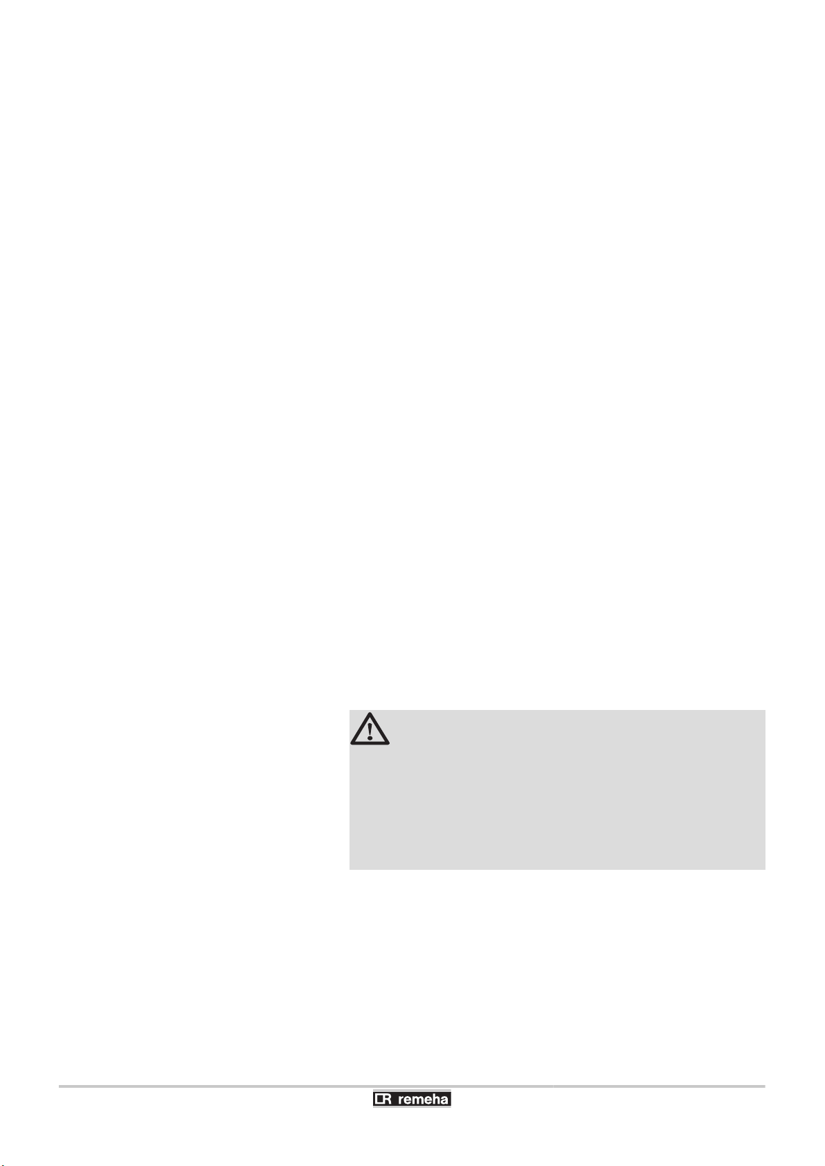
4. Installation
Calenta 25s - 28c - 35s - 40c
The status indicator D3 at the top right of the control PCB indicates
the status:
4 Continuous signal: PCB working normally
4 Flashing signal: No connection
4 No signal: No voltage or faulty PCB (Check the wiring)
Control of external central heating pump (Pump)
n
An external central heating pump can be connected to the Pump
terminals of the connector. The maximum input power is 400 VA.
Control of external three-way valve (3wV)
n
The external three-way valve (230 VAC) can be used when
connecting an indirectly heated calorifier. The neutral position of the
three-way valve can be set using parameter p34.
The three-way valve is connected as follows:
4 N = neutral
4 C = central heating
4 D = tank
Control of external sanitary hot water pump (3wV)
n
It is also possible to connect an external DHW pump to the terminals
3wV. Connect the pump as follows:
4 N = N pump
4 D = L pump
4 Q = PE pump
CAUTION
If the neutral position of the three-way valve is adjusted
with parameter p34, the pump should be connected as
follows:
4 N = N pump
4 C = L pump
4 Q = PE pump
48
Control of external gas valve (EgV)
n
If there is a heat demand, an alternating voltage of 230 VAC, 1 A
(maximum) becomes available on the EgV terminals of the connector
to control an external gas valve.
040412 - 7600585-01

Calenta 25s - 28c - 35s - 40c 4. Installation
Operation signal and failure signal (Status)
n
The alarm or operation signal is selected using parameter p40.
4 If the boiler is operating, the operation signal can be switched via
a potential-free contact (maximum 230 VAC, 1 A) on the No and
C terminals of the connector.
4 If the boiler locks out, the alarm can be transmitted via a potential-
free contact (maximum 230 VAC, 1 A) on the Nc and C terminals
of the connector.
Solar DHW sensor Tsol
n
The solar boiler temperature is controlled using a sensor. Connect
this sensor to the connector terminals Tsol.
Pressure switch minimum Gps
n
The minimum gas pressure switch shuts the boiler down if the inlet
gas pressure becomes too low. Connect the minimum gas pressure
switch to the Gps terminals of the connector. The presence of the gas
pressure switch must be set using parameter p41.
Heat Recovery Unit (Hru)
n
Connect the wires from the heat recovery unit to the Hru terminals of
the connector. The presence of the heat recovery unit must be set
using parameter p4".
040412 - 7600585-01
49

T001047-G
2 31
K1
X1
X14
X13
X12
X3
X2
X4
X5
X6
X7
X8
X9
X10
X11
1
PC
OT OS WS
HLS
1 2 7 8 9 103 4 5 6
X6
1 2 3
GN/
YW
WH
BL
153
X21
X8
1 2 3
BR
BL
GN/
YW
3 1 2
X41
SCUSCU
1 2 3 4 5 6
WH
GY
OR
RD
GN
YW
X7
1 2 3
WH
BK
RD
1 3 2
X121
X5
2 3 4 1
E
BK
BL
GN/
YW
GY
1 23
X22
PWM
PUMP
12 13
BK
BK
1 2
X116
FTSRTS
9
RD
1
BK
1
2 2
X115
8
BL
1
22
X114
PS
10 11
BK
BK
3 1
X112
FS
2 3
BK
BK
1 3
X113
4 5 7 6
X111
BK
BK
BK
BK
1 2 3 4
PSU
X9
2 3 4 5
X91
BK
BK
BK
BK
1 2 4 5
1
BK
BK
1
2
X117
P
230V, 50Hz
L N
SCU
X2
1 32
BL
BR
GN/
YW
X1
1 23
BR
BL
GN/YW
DIS
1 10
1 10
X3
4 3 2 15
BR
BL
BR
BL
GN/
YW
3 1
4 2
X51
GB PUMP ADV
IT FAN
S
X13
X12
X11
X10
X14
4. Installation Calenta 25s - 28c - 35s - 40c
4.11 Electrical diagram
P
Power supply
SCU
Extended control PCB
S
On/Off switch
IT
Ignition transformer
E
Ignition power relay
GB
Combined venturi and gas valve unit
DV
3-way valve
50
PSU
OT
OS
WS
PC
DIS
Storage parameter
Thermostat
Outside sensor
DHW sensor
Connecting a computer
Display
PUMP A
HLS
FAN
FS
RTS
FTS
PS
Shunt pump
Safety thermostat
Fan
Flow switch
Return sensor
Flow sensor
Pressure sensor
040412 - 7600585-01

T001523-B
Calenta 25s - 28c - 35s - 40c 4. Installation
4.12 Filling the system
4.12.1. Water treatment
In most cases, the boiler and the central heating installation can be
filled with normal tap water and no water treatment will be necessary.
WARNING
Do not add chemical products to the central heating water
without consulting Remeha. For example: antifreeze,
water softeners, products to increase or reduce the pH
value, chemical additives and/or inhibitors. These may
cause faults in the boiler and damage the heat exchanger.
4 Rinse the central heating installation with at least 3x
the volume of the central heating installation. Flush
the DHW pipes with at least 20 times the volume of
the pipes.
4 For untreated water, the pH value of the water in the
installation must be between 7 and 9 and for treated
water between 7 and 8,5.
4 The maximum hardness of the water in the installation
must be between 0,5 - 20,0 °dH (Depending on the
total installed heat output).
4 For more information, refer to our publication water
quality rules. The rules in the aforementioned
document must be respected.
4.12.2. Filling the siphon
1. Remove the siphon.
2. Fill the siphon with water. This must be filled up to the level
markers.
3. Re-assemble the siphon.
CAUTION
4 Fill the water siphon before starting the boiler to avoid
combustion products escaping from the boiler.
4 Mount the vent hose above the siphon.
040412 - 7600585-01
51

1
2
3
4
T000181-B
T001574-B
T001507-B
4. Installation Calenta 25s - 28c - 35s - 40c
4.12.3. Filling the system
CAUTION
Before filling, open the valves on every radiator in the
installation.
In order to be able to read off the water pressure from the
boiler display, the boiler must be switched on.
1. Fill the system with clean tap water (advised water pressure is
between 1,5 and 2 bar).
2. Check the tightness of the water connections.
After switching on the power and if there is adequate water
pressure, the boiler always runs through an automatic
venting program lasting approximately 3 minutes (During
filling, air can escape from the system via the automatic air
vent). If the water pressure is lower than 0,8 bar, the symbol
e will appear. If necessary, top up the water level in the
heating system (recommended hydraulic pressure
between 1,5 and 2 bar).
CAUTION
4 The filling must be carried out within 30 minutes,
otherwise the venting program starts and that would
be undesirable if the device is not filled. Switch off the
boiler if the central heating system is not being
topped up immediately.
4 When venting, prevent water from getting into the
boiler casing and electrical parts of the boiler
52
040412 - 7600585-01

T001996-A
1
2 3 4 5 8
6 7
Calenta 25s - 28c - 35s - 40c 5. Commissioning
5 Commissioning
5.1 Control panel
5.1.1. Functions of the keys
1
2
3
4
5
6
Display
> [Escape] or J key
D Heating temperature key or [-]
N DHW temperature key or [+]
S [Enter] or cancel d Key lock-out
B [Chimney-sweeping] keys
(press the 2 and 3 keys simultaneously)
7
f [Menu] keys
(press the 4 and 5 keys simultaneously)
8
a On/off switch
The display has several positions and symbols and provides
information on the operating condition of the boiler and any possible
failures. A service message may also appear in the display. Numbers,
dots and/or letters may be displayed. The symbols located above the
function keys indicate their current function.
4 The display content can be changed using parameter p6.
4 The brightness of the display lighting can be changed using
parameter p8.
Information menu:
Reading the various current values.
Q
Chimney-sweeping position:
B
Forced full or part load for CO2 measurement.
User menu:
W
Parameters at user level can be changed.
Heating programme deactivated:
C
The heating function is deactivated.
040412 - 7600585-01
Key lock-out is activated by setting parameter p6 to 3. If no key is
pressed for 3 minutes, the display lighting switches off and only the
current water pressure, the > key and the d symbol are
displayed. Press the S key for about 2 seconds to reactivate the
display and other keys. The d symbol disappears from the display.
5.1.2. Meaning of the symbols on the display
On/Off switch:
After 5 lock-outs, the boiler must be switched off/on
a
again.
Shunt pump:
b
The pump operates.
Central heating function:
D
Access to central heating temperature parameter.
DHW function:
N
Access to sanitary hot water temperature parameter.
53

5. Commissioning
Calenta 25s - 28c - 35s - 40c
Manual mode:
E
Boiler is set to manual operation.
DHW programme deactivated:
T
The DHW mode is deactivated.
Service menu:
?
Parameters at installer level can be changed.
Energy-saving mode:
)
Economic mode activated.
Defect:
Boiler indicates a fault. This can be seen from the e code
c
and red display.
Frost protection:
]
Boiler is running in frost protection mode.
Hour counter menu:
Readout of the operating hours, number of successful
\
starts and hours on mains supply.
K
e
g
[
I
d
5.2 Check points before commissioning
5.2.1. Preparing the boiler for commissioning
Yellow display with the symbols:
$ + K + Z (Maintenance message).
Water pressure:
The water pressure is too low.
Battery symbol:
Status of battery of wireless controller.
Signal strength symbol:
Signal strength of the wireless controller.
Burner level:
Boiler is running at full or low load.
Locking the keys:
Key lock-out is activated.
WARNING
Do not put the boiler into operation if the supplied gas is
not in accordance with the approved gas types.
Preparatory procedure for boiler commissioning:
4 Check that the gas type supplied matches the data shown on the
boiler's data plate.
4 Check the gas circuit.
4 Check the hydraulic circuit.
4 Check the water pressure in the heating system.
4 Check the electrical connections to the thermostat and the other
external controls.
4 Check the other connections.
4 Test the boiler at full load. Check the setting of the gas/air ratio
and, if necessary, correct it.
4 Test the boiler at part load. Check the setting of the gas/air ratio
and, if necessary, correct it.
4 Finalizing work.
54
040412 - 7600585-01

T001518-B
C
Calenta 25s - 28c - 35s - 40c
5. Commissioning
5.2.2. Gas circuit
WARNING
Ensure that the boiler is switched off.
1. Open the main gas supply.
2. Unscrew the two screws located under the front panel by a quarter
turn and remove the panel.
3. Tilt the control box forwards by opening the holding clips located
at the sides.
4. Check the gas supply pressure at the pressure outlet C on the gas
valve unit.
WARNING
To ascertain the gas types permitted, see chapter:
¼
"Equipment categories", page 9
5. Check the tightness of the gas connections made after the gas
valve unit in the boiler.
6. Check the tightness of the gas line, including the gas valves. The
test pressure must not exceed 60 mbar.
7. Purge the gas supply pipe within the boiler by unscrewing the
pressure outlet on the gas block. Tighten the measurement point
when the pipe has been sufficiently purged.
8. Check the tightness of the gas connections in the boiler.
5.3 Commissioning the boiler
5.2.3. Hydraulic circuit
4 Check the condensate discharge siphon; it must be filled with
clean water up to the mark.
4 Check that there are no leaks on the hydraulic connections.
5.2.4. Electrical connections
4 Check the electrical connections, particularly the earth.
4 Check the electrical connections to the thermostat and the other
external controls.
1. Tilt the control box upwards again and fasten it using the clips
located at the sides.
2. Open the main gas supply.
3. Open the gas valve on the boiler.
4. Insert the boiler plug into an earthing socket.
5. Turn on the boiler using the on/off switch.
040412 - 7600585-01
55

5. Commissioning Calenta 25s - 28c - 35s - 40c
6. Set the controls (thermostats, control system) so that they request
heat.
7. The start-up cycle begins and cannot be interrupted. During the
start-up cycle, the display shows the following information:
A short test where all segments of the display are visible.
fK[xx
pK[xx
: Software version
: Parameter version
The version numbers are displayed alternately.
8. A vent cycle of a duration of around 3 minutes is carried out
automatically.
If a DHW sensor is connected and the anti-legionella
function is activated, the boiler starts to heat the water in
the DHW tank as soon as the vent programme has been
completed.
By pressing the S key for a short time, the current operating status
is shown on the display:
Heat demand 5D
1 : Fan ON 1 : Post-ventilation 1 : Fan ON 1 : Post-ventilation
" : Boiler is igniting 5 : Burner stop " : Boiler is igniting 5 : Burner stop
3 : Heating System 0 : Standby 4 : Domestic hot water mode 0 : Standby
Heat demand stopped
6 : Post-circulation of the pump
Hot tap water demand N
Heat demand stopped
6 : Post-circulation of the pump
In addition to 0, in STAND-BY the display normally shows the water
pressure and the symbols 5D, 5H and N.
Error during the start-up procedure:
4 No information is shown on the display:
- Check the mains supply voltage
- Check the main fuses
- Check the fuses on the control panel:
(F1 = 6,3 AT, F2 = 2 AT)
- Check the connection of the mains lead to the connector X1 in
the instrument box
4 A fault is indicated on the display by the fault symbol c and a
flashing fault code.
- The meaning of the error codes is given in the error table.
- Press for 3 seconds on key J to restart the boiler.
If the economy setting (eco setting) is on, then, after central
heating operation, the boiler will not start to run for hot tap
water production.
56
040412 - 7600585-01

T001526-A
Calenta 25s - 28c - 35s - 40c 5. Commissioning
5.4 Gas settings
5.4.1. Adapting to another gas type
WARNING
Only a qualified engineer may carry out the following
operations.
The boiler is preset in the factory to operate on natural gas G25 (Gas
L).
4 If the boiler is converted, for example, to:
- G20 (Gas H)
- G31 (Propane)
It is necessary to mention on the sticker provided: This
boiler has been set for.... This sticker must be affixed
to the top of the boiler next to the identification plate.
4 If operating on propane, Remeha cannot guarantee
compliance with all aspects of comfort in accordance
with the CW label.
For operation on another group of gases, carry out the following
operations:
4 Regulate the fan speed as indicated in the table (if required). The
setting can be modified using parameters p17, p18,
p19 and p20:
¼ See chapter: "Parameter descriptions", page 64
4 Set the air/gas ratio. For more detailed information:
¼ See chapter: "Setting the air/gas ratio (Full load)", page
57
¼ See chapter: "Setting the air/gas ratio (Part load)", page
59
5.4.2. Setting the air/gas ratio (Full load)
1. Unscrew the plug of the flue gas measurement point.
2. Connect the flue gas analyser.
WARNING
Ensure that the opening around the sensor is completely
sealed when taking measurements.
040412 - 7600585-01
57

T001586-A
rpm
kWµA
± 30l/min
barPsi
St ºC
ºCºFh
A
T000932-A
5. Commissioning Calenta 25s - 28c - 35s - 40c
3. Set the boiler to full load. Press the two B keys simultaneously.
The display shows
. The symbol B appears.
h3
4. Measure the percentage of O2 or CO2 in the flue gases (Front
panel removed).
5. If this rate does not match the required value, correct the gas/air
ratio using the adjustment screw A on the gas valve unit.
6. Check the flame through the flame inspection window.
The flame must not be detached.
O2/CO2 control and setting values at full load for G20 (Gas H)
Boiler type Setting value Checking value
O 2 (%) CO 2 (%) O 2 (%) CO 2 (%)
Calenta 25s 5,2 ± 0,4 8,8 ± 0,2 5,2 ± 0,5 8,8 ± 0,3
Calenta 28c 5,2 ± 0,4 8,8 ± 0,2 5,2 ± 0,5 8,8 ± 0,3
Calenta 35s 4,8 ± 0,4 9,0 ± 0,2 4,8 ± 0,5 9,0 ± 0,3
Calenta 40c 4,8 ± 0,4 9,0 ± 0,2 4,8 ± 0,5 9,0 ± 0,3
O2/CO2 control and setting values at full load for G25 (Gas L)
Boiler type Setting value Checking value
O 2 (%) CO 2 (%) O 2 (%) CO 2 (%)
Calenta 25s 5,0 ± 0,4 8,8 ± 0,2 5,0 ± 0,5 8,8 ± 0,3
Calenta 28c 5,0 ± 0,4 8,8 ± 0,2 5,0 ± 0,5 8,8 ± 0,3
Calenta 35s 4,5 ± 0,4 9,1 ± 0,2 4,5 ± 0,5 9,1 ± 0,3
Calenta 40c 4,5 ± 0,4 9,1 ± 0,2 4,5 ± 0,5 9,1 ± 0,3
Diameter of the gas diaphragm (x.xx) O2/CO2 control and setting values at full load for G31 (Propane)
Fit the gas restrictor in the gas block Boiler type Setting value Checking value
Ø mm O 2 (%) CO 2 (%) O 2 (%) CO 2 (%)
4,00 Calenta 25s 5,2 ± 0,3 10,3 ± 0,2 5,2 ± 0,5 10,3 ± 0,3
4,00 Calenta 28c 5,2 ± 0,3 10,3 ± 0,2 5,2 ± 0,5 10,3 ± 0,3
- Calenta 35s 5,2 ± 0,3 10,3 ± 0,2 5,2 ± 0,5 10,3 ± 0,3
- Calenta 40c 5,2 ± 0,3 10,3 ± 0,2 5,2 ± 0,5 10,3 ± 0,3
58
040412 - 7600585-01

T001526-A
T001587-A
rpm
kWµA
± 30l/min
barPsi
St ºC
ºCºFh
B
T000933-B
B
Calenta 25s - 28c - 35s - 40c 5. Commissioning
5.4.3. Setting the air/gas ratio (Part load)
1. Unscrew the plug of the flue gas measurement point.
2. Connect the flue gas analyser.
WARNING
Ensure that the opening around the sensor is completely
sealed when taking measurements.
3. Set the boiler to part load. Press the two B keys
simultaneously. The symbol B appears. Press the [-] key several
times until
4. Measure the percentage of O2 or CO2 in the flue gases (Front
panel removed).
is displayed on the screen.
l3
5. If this rate does not match the required value, correct the gas/air
ratio using the adjustment screw B on the gas valve unit.
4
Turn the screw B anticlockwise to obtain a lower
CO2 value.
4 Turn the screw B clockwise to obtain a higher CO
2
value.
6. Check the flame through the flame inspection window.
The flame must be stable and blue in colour with orange
particles around the edge of the burner.
O2/CO2 control and setting values at part load for G20 (Gas H)
Boiler type Setting value Checking value
O 2 (%) CO 2 (%) O 2 (%) CO 2 (%)
Calenta 25s 5,9 ± 0,4 8,4 ± 0,2 5,9 ± 0,4 8,4 ± 0,2
Calenta 28c 5,9 ± 0,4 8,4 ± 0,2 5,9 ± 0,4 8,4 ± 0,2
Calenta 35s 5,5 ± 0,4 8,6 ± 0,2 5,5 ± 0,4 8,6 ± 0,2
Calenta 40c 5,5 ± 0,4 8,6 ± 0,2 5,5 ± 0,4 8,6 ± 0,2
O2/CO2 control and setting values at part load for G25 (Gas L)
Boiler type Setting value Checking value
O 2 (%) CO 2 (%) O 2 (%) CO 2 (%)
Calenta 25s 5,7 ± 0,4 8,4 ± 0,2 5,7 ± 0,4 8,4 ± 0,2
Calenta 28c 5,7 ± 0,4 8,4 ± 0,2 5,7 ± 0,4 8,4 ± 0,2
Calenta 35s 5,2 ± 0,4 8,7 ± 0,2 5,2 ± 0,4 8,7 ± 0,2
Calenta 40c 5,2 ± 0,4 8,7 ± 0,2 5,2 ± 0,4 8,7 ± 0,2
040412 - 7600585-01
59

B
T001985-B
A
8
9 10
T001522-A
5. Commissioning
Calenta 25s - 28c - 35s - 40c
O2/CO2 control and setting values at part load for G31 (Propane)
Boiler type Setting value Checking value
O 2 (%) CO 2 (%) O 2 (%) CO 2 (%)
Calenta 25s 5,8 ± 0,3 9,9 ± 0,2 5,8 ± 0,3 9,9 ± 0,2
Calenta 28c 5,8 ± 0,3 9,9 ± 0,2 5,8 ± 0,3 9,9 ± 0,2
Calenta 35s 5,8 ± 0,3 9,9 ± 0,2 5,8 ± 0,3 9,9 ± 0,2
Calenta 40c 5,8 ± 0,3 9,9 ± 0,2 5,8 ± 0,3 9,9 ± 0,2
Repeat the high speed test and the low speed test as often
as necessary until the correct values are obtained without
having to make additional adjustments.
5.4.4. Basic setting for the gas/air ratio
If the gas/air ratio is out of adjustment, the gas valve unit has a basic
setting. To do this, proceed as follows:
1. Cut the power supply to the boiler.
2. Close the gas valve on the boiler.
3. Remove the air inlet flue on the venturi.
4. Unscrew the top connection on the gas valve unit.
5. Disconnect the connector located under the fan.
6. Release the 2 clips holding the fan/mixing elbow unit in place on
the heat exchanger.
7. Completely remove the fan/mixing elbow unit.
For steps 3 to 7 inclusive, see chapter: "Checking the burner
¼
and cleaning the heat exchanger", page 78
8. Turn the setting screw A on the gas valve unit to modify the
position of the restrictor.
9. Turn the setting screw B on the gas valve unit anticlockwise until
it matches the front panel.
10.Turn the setting screw B on the gas valve unit by 6 turns clockwise.
11.Follow the procedure in reverse to re-assemble all of the
components.
5.5 Checks and adjustments after commissioning
60
5.5.1. Finalizing work
1. Remove the measuring equipment.
2. Put the flue gas sampling plug back in place.
3. Refit the front panel. Tighten the two screws by a quarter turn.
4. Push key
5. Raise the temperature in the heating system to approximately
70°C.
6. Shut down the boiler.
7. After about 10 minutes, vent the air in the heating system.
8. Switch on the boiler.
to return the boiler to normal operating mode.
>
040412 - 7600585-01

Calenta 25s - 28c - 35s - 40c 5. Commissioning
9. Check the tightness of the flue gases evacuation and air inlet
connections.
10.Checking the hydraulic pressure. If necessary, top up the water
level in the heating system (recommended hydraulic pressure
between 1,5 and 2 bar).
11.Tick the gas category used on the data plate.
12.Complete the checklist in the supplied service book.
13.Explain the operation of the installation, the boiler and the
regulator to the users.
14.Give all the instruction manuals to the user.
15.Together with the end user, fill in the warranty sheet provided.
16.Confirm the commissioning with a signature and a company
stamp.
5.6 Reading out measured values
5.6.1. Reading the various current values
The following current values can be read off the information menu
Q:
4 5t = State.
4 5v = Sub-status.
4 t1 = Supply temperature (°C).
4 t" = Return temperature (°C).
4 t3 = Calorifier temperature (°C).
4 t4 = Outside temperature (°C) (Only with an outside
temperature sensor).
4 t5 = Solar boiler temperature (°C).
4 5p = Internal set point (°C).
4 fl = Ionization current (µA).
4 Mf = Fan speed in rpm.
4 pr = Water pressure (bar).
4 p; = Supplied relative heat output (%).
040412 - 7600585-01
61

T000810-F
4x
2x
T000816-G
5x
2x
5. Commissioning
Calenta 25s - 28c - 35s - 40c
The current values can be read as follows:
1. Press the two f keys simultaneously. The symbol Q flashes.
2. Confirm using key S.
is displayed, alternating with the
5t
current status 3 (for example).
3. Press the [+] key.
sub-status
(for example).
30
4. Press the [+] key.
flow temperature
is displayed, alternating with the current
5v
is displayed, alternating with the current
t1
°C (for example).
60
5. Press the [+] key successively to scroll down the various
parameters.
t", t3, t4, t5
6. Press the [+] key.
set point
°C (for example).
88
7. Press the [+] key.
ionization current
8. Press the [+] key.
fan rotation speed
9. Press the [+] key.
water pressure
#0
is displayed, alternating with the internal
5p
is displayed, alternating with the current
fl
µA (for example).
70
is displayed, alternating with the current
Mf
3000
pr
rpm (for example).
is displayed, alternating with the current
bar (for example). If no water pressure sensor
.
is connected, [-.-] appears on the display.
10.Press the [+] key.
modulation percentage
11.Press the [+] key. The readout cycle starts again with
12.Press the
key 2 times to return to the current operating
>
is displayed, alternating with the current
p;
% (for example).
78
5t
mode.
.
5.6.2. Readout from the hour counter and
percentage of successful starts
1. Press the two keys f simultaneously and then key [+] until the
symbol \ flashes on the menu bar.
2. Press the S key.
operation
3600
3. Press the [+] key. The display shows D.
alternating with the number of operating hours in central heating
operation
4. Press the [+] key. The display shows N.
560
alternating with the number of operating hours used for heating
tap water
320
(for example).
5. Press the [+] key. The display shows @.
alternating with the percentage of successful starts
example).
6. Press the
key 2 times to return to the current operating
>
mode.
and the number of hours of boiler
hr
(for example) are displayed alternately.
is displayed,
hr
(for example).
is displayed,
hr
is displayed,
5Z
92
% (for
62
040412 - 7600585-01

Calenta 25s - 28c - 35s - 40c 5. Commissioning
5.6.3. Status and sub-status
The information menu Q gives the following status and sub-status
numbers:
State 5t Sub-status 5v
0
1
2
3 / 4 Burner for central heating operation / DHW System
5
6
8
9
17
Rest
Boiler start (Heat demand)
Burner start
Burner stop
Boiler stop (End of heat demand)
Control stop
Blocking
Bleed
0
Rest
1
Anti-hunting
2
Control three-way valve
3
Start pump
4
Wait for the correct temperatures for burner start
10
Open flue gas damper/external gas valve
11
Increase fan speed
13
Pre-ventilation
14
Wait for release signal
15
Burner on
17
Pre-ignition
18
Main ignition
19
Flame detection
"0
Intermediate ventilation
30
Temperature control
31
Limited temperature control (ΔT safety)
32
Output control
33
Increase protection level 1 (Modulate down)
34
Increase protection level 2 (Part load)
35
Increase protection level 3 (Blockage)
36
Modulate up for flame control
37
Temperature stabilisation time
38
Cold start
40
Burner off
41
Post ventilation
42
Close flue gas damper/external gas valve
43
Recirculation protection
44
Stop fan
60
Pump post circulation
61
Pump off
62
Control three-way valve
63
Start anti-hunting
0
Wait for burner start
1
Anti-hunting
xx
Shutdown code xx
0
Rest
2
Control three-way valve
3
Start pump
61
Pump off
62
Control three-way valve
040412 - 7600585-01
63

5. Commissioning Calenta 25s - 28c - 35s - 40c
5.7 Changing the settings
The boiler control panel is set for the most common heating
systems. With these settings, practically all heating systems operate
correctly. The user or installer can optimise the parameters according
to own preferences.
5.7.1. Parameter descriptions
Factory setting
Parameter
p1
p2
p3
p4
p5
p6
p7
p8
p17
p18
(1) Do not modify these factory settings unless absolutely necessary. For example, for modification of the boiler for: G20 (H gas) or G31 (propane),
high pressure systems, WTW coupling or CLV overpressure
Description Adjustment range
Supply temperature: T
Domestic hot water temperature:
T
SET
Heating / DHW mode
ECO mode
Anticipation resistance
Display screen
Post-circulation of the pump
Brightness of display lighting
Maximum fan speed (Heating)
Maximum fan speed (DHW)
SET
20 to 90 °C
40 to 65 °C
0 = Heating deactivated / DHW deactivated
1 = Heating activated / DHW activated
2 = Heating activated / DHW deactivated
3 = Heating deactivated / DHW activated
0 = Comfort
1 = Energy-saving mode
2 = Management using a programmable thermostat
0 = No anticipation resistance for the ON/OFF
thermostat
1 = Anticipation resistance for the ON/OFF thermostat
0 = Simple
1 = Comprehensive
2 = Automatic switching to simple after 3 minutes
3 = Automatic switching to simple after 3 minutes; Key
blocking is active
1 to 98 minutes
99 minutes = continuous
0 = Dimmed
1 = Bright
G25 (Gas L)
(x100 rpm)
G20 (Gas H)
(x100 rpm)
G31 (Propane)
(x100 rpm)
G25 (Gas L)
(x100 rpm)
G20 (Gas H)
(x100 rpm)
G31 (Propane)
(x100 rpm)
(1)
(1)
Calenta
25s 28c 35s 40c
80
60
1
2
0
2
1
1
56 46 62 42
56 46 62 42
53 43 62 42
56 62 62 68
56 62 62 68
53 59 62 68
64
040412 - 7600585-01

Calenta 25s - 28c - 35s - 40c 5. Commissioning
Factory setting
Parameter Description Adjustment range
Calenta
25s 28c 35s 40c
(1)
18 18 17 17
18 18 17 17
18 18 18 17
p19
Minimum fan speed (Heating
+DHW)
G25 (Gas L)
(x100 rpm)
G20 (Gas H)
(x100 rpm)
G31 (Propane)
(x100 rpm)
CLV overpressure (combusted gas discharge
systems)
21 21 23 23
(x100 rpm)
G25 (Gas L)
(1)
50 50 75 75
G20 (Gas H) 50 50 75 75
p20
p21
p22
p23
p24
p25
p26
p27
p28
Minimum fan speed (offset)
Start speed
G31 (Propane) 50 50 75 75
CLV overpressure (combusted gas discharge
systems)
Do not modify
(x100 rpm)
50 50 40 40
30 30 40 40
Minimum water pressure 0 - 3 bar(x 0,1 bar) 8
Maximum flow temperature of
0 to 90 °C
system
Anti-hunting differential for central
-15 to 15 °C
heating operation
Heat curve set point
(Maximum outside temperature)
Heat curve set point
(Supply temperature)
Heat curve set point
(Minimum outside temperature)
Setting the pump speed
0 to 30 °C
(Only with an outside temperature sensor)
0 to 90 °C
(Only with an outside temperature sensor)
-30 to 0 °C
(Only with an outside temperature sensor)
2 - 10 (x 10 % )
-15
(Minimum pump speed for central
90
3
20
20
2
heating operation)
p29
Setting the pump speed
(Maximum pump speed for
2 - 10 (x 10 % )
6
central heating operation)
p30
Antifreeze temperature from - 30 to 0°C -10
0 = Stop
1 = Start
p31
Legionella protection
(After commissioning, the boiler will operate once a
1 0 1 0
week at 65°C for DHW)
2 = Management using a programmable thermostat
p32
p33
p34
p35
Set point increase for calorifier 0 to 20 °C 15
DHW cut-in temperature DHW
sensor
Control of three-way valve
Boiler type
from 2 to 15°C 6
0 = Normal
1 = Reverse
0 = Heating and instant domestic hot water
1 = Heating only
1 0 1 0
0
0 = Heating activated
p36
Shutdown input function
1 = Shutdown without frost-protection
2 = Shutdown with frost protection
1
3 = Lock-out with frost protection (Pump only)
p37
(1) Do not modify these factory settings unless absolutely necessary. For example, for modification of the boiler for: G20 (H gas) or G31 (propane),
high pressure systems, WTW coupling or CLV overpressure
Release function
0 = Hot water on
1 = Release input
1
040412 - 7600585-01
65

T001906-B
1x
2x
5. Commissioning
Parameter Description Adjustment range
p38
p39
p40
p41
p42
p43
p44
p45
p46
Zd
df and dV
(1) Do not modify these factory settings unless absolutely necessary. For example, for modification of the boiler for: G20 (H gas) or G31 (propane),
high pressure systems, WTW coupling or CLV overpressure
Release waiting time 0 to 255 seconds 0
Gas valve switching time 0 to 255 seconds 0
Fault relay function (Optional)
GpS connected (Optional)
HRU connected (Optional)
Mains detection phase
Maintenance message Do not modify 1
Service operating hours Do not modify 175
Service burning hours Do not modify 30
Detection of connected SCUs
Factory setting
0 = Operation signal
1 = Alarm signal
0 = Not connected
1 = Connected
0 = Not connected
1 = Connected
0 = Stop
1 = Start
0 = No detection
1 = Detection
To restore the factory settings or when replacing the
main PCB, enter the values dF and dU from the type
plate in parameters df and dV
Calenta 25s - 28c - 35s - 40c
Factory setting
Calenta
25s 28c 35s 40c
1
0
0
0
0
X
Y
5.7.2. Modification of the user-level parameters
Parameters p1 to p8 can be modified by the user in order to meet
central heating and DHW comfort needs.
CAUTION
Modification of the factory settings may be detrimental to
the functioning of the appliance.
1. Press the two keys f simultaneously and then key [+] until the
symbol W flashes on the menu bar.
2. Select the users menu using the key S.
flashing.
1
3. Press the S key a second time. The value
flashes (for example).
4. Change the value by pressing the [-] or [+] key. In this example
using key [-] to
5. Confirm the value with the S key.
60
°C.
p[1
flashing.
6. Press the
key 2 times to return to the current operating
>
mode.
is displayed with
p[1
°C appears and
80
is displayed with
1
66
040412 - 7600585-01

T000819-E
3x
2x
Calenta 25s - 28c - 35s - 40c 5. Commissioning
4 The parameters p1 to p8 are changed in the
same way as p1. After step 2, use the [+] key to
move to the required parameter.
4 The parameters p1 (the maximum heating water
temperature) and p2 (the maximum drinking water
temperature) can also be modified using the quick
selection menu.
5.7.3. Modification of the installer-level
parameters
Parameters p17 to df must only be modified by a qualified
professional. To prevent unwanted settings, some parameter settings
can only be changed after the special access code 0012 is
entered.
If the boiler has been modified, for example:
4 G20 (Gas H) or G31 (Propane)
4 high pressure systems
4 WTW coupling
4 CLV overpressure (combusted gas discharge
systems)
It is necessary to mention on the sticker provided: This
boiler has been set for.... This sticker must be affixed to the
top of the boiler next to the identification plate.
CAUTION
Modification of the factory settings may be detrimental to
the functioning of the appliance.
1. Press the two keys f simultaneously and then key [+] until the
symbol ? flashes on the menu bar.
2.
Select the fitter menu using the key.
c0de
appears on the
display.
3. Use keys [-] or [+] to input the installer code
4. Confirm using key S.
is displayed with 1 flashing.
p[1
5. Press the S key a second time. The value
0012
80
.
°C appears and
flashes (for example).
6. Change the value by pressing the [-] or [+] key. In this example
using key [-] to
7. Confirm the value with the S key:
60
°C.
is displayed with
p[1
1
flashing.
8. If necessary, set other parameters by selecting them using the
[-] or [+] keys.
9. Press the
key 2 times to return to the current operating
>
mode.
The boiler also returns to operating status if no keys are
pressed for 3 minutes.
040412 - 7600585-01
67
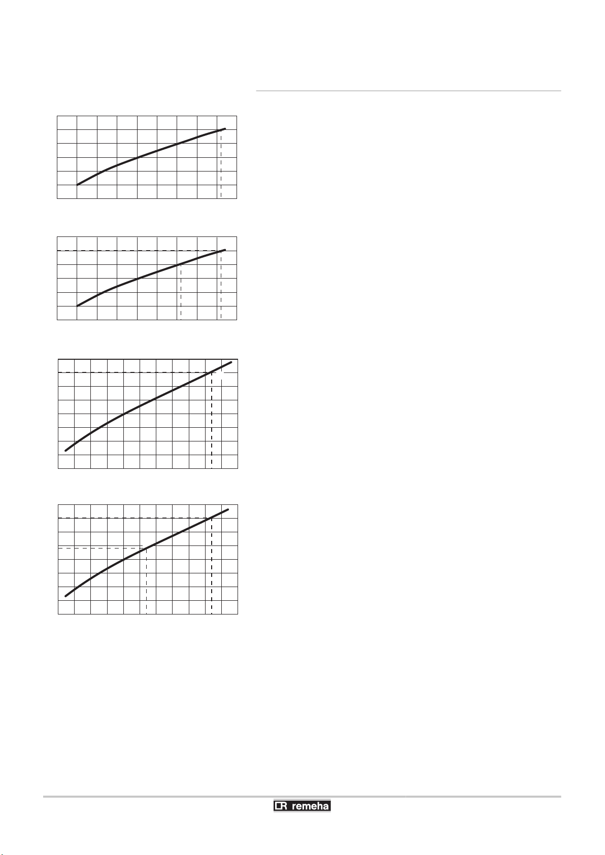
T001848-B
1500
0
5
10
15
20
25
30
2000 2500 3000 3500 4000 4500
5600
5000 5500 6000
F
R
Q
M
T001847-A
1500
0
5
10
15
20
25
30
2000 2500 3000 3500 4000 4500
4600 5600
5000 5500 6000
F
R
Q
M
T001966-B
2000 3000 4000 5000 6000 7000
0
5
10
15
20
25
30
35
40
6200
F
R
Q
M
T001967-B
2000 3000 4000 5000 6000 7000
0
5
10
15
20
24
30
35
40
6200
R
Q
M
6200
4200
F
5. Commissioning Calenta 25s - 28c - 35s - 40c
5.7.4. Setting the maximum heat input for central
heating operation
Calenta 25s
M
F
Q
R
Calenta 28c
M
F
Q
R
Calenta 35s
M
F
Q
Maximum heat input
Factory setting
Power input (kW)
Fan rotation speed (rpm)
Maximum heat input
Factory setting
Power input (kW)
Fan rotation speed (rpm)
Maximum heat input
Factory setting
Power input (kW)
68
R
Calenta 40c
M
F
Q
R
Fan rotation speed (rpm)
Maximum heat input
Factory setting
Power input (kW)
Fan rotation speed (rpm)
040412 - 7600585-01

T001628-A
3x
...x
...x
2x
T000820-H
3x
...x
Calenta 25s - 28c - 35s - 40c
5. Commissioning
See the graphs for the relationship between heat input and speed for
natural gas. The speed can be changed using parameter p17. To
do this, proceed as follows:
1. Press the two keys f simultaneously and then key [+] until the
symbol ? flashes on the menu bar.
2. Select the installers menu using the key S.
c0de
appears
on the display.
3. Use keys [-] or [+] to input the installer code
4. Confirm using key S.
5. Press the [+] key to go to parameter
is displayed with 1 flashing.
p[1
p[17
0012
.
.
6. Confirm using key S.
7. Press the [+] key to increase the speed from
(see the graphs for the associated heat output).
50
to, for example,
46
8. Confirm the value with the S key.
9. Press the
key 2 times to return to the current operating
>
mode.
5.7.5. Return to the factory settings
1. Press the two keys f simultaneously and then key [+] until the
symbol ? flashes on the menu bar.
2. Select the installers menu using the key S.
c0de
on the display.
3. Use keys [-] or [+] to input the installer code
4. Confirm using key S.
5. Press the [+] key several times.
is displayed with 1 flashing.
p[1
p[df
0012
is displayed with
flashing.
6. Press the S key.
df[x
is displayed with x flashing. This is
the current value of X for dF. Check this against the value of X on
the type plate.
7. Enter the value of X shown on the type plate using the [-] or [+]
key.
8. Confirm the value with the S key,
df[y
is displayed with
flashing. This is the current value of Y for dU. Check this against
the value of Y on the type plate.
9. Enter the value of Y shown on the type plate using the [-] or [+]
key.
10.Confirm the value with the S key. The factory settings are reset.
11.The display returns to the current operating mode.
appears
.
df
y
040412 - 7600585-01
69

T000445-B
3x
...x
T000824-E
2x
2x
bar
5. Commissioning
Calenta 25s - 28c - 35s - 40c
5.7.6. Carrying out an auto-detect
After removing a control PCB, an auto-detect must be carried out. To
do this, proceed as follows:
1. Press the two keys f simultaneously and then key [+] until the
symbol ? flashes on the menu bar.
2. Select the installers menu using the key S.
c0de
appears
on the display.
3. Use keys [-] or [+] to input the installer code
4. Confirm using key S.
5. Press the [+] key several times.
is displayed with 1 flashing.
p[1
p[Zd
is displayed with
0012
.
Zd
flashing.
6. Confirm using key S. Auto-detect is carried out.
7. The display returns to the current operating mode.
5.7.7. Setting the manual mode
In some cases it may be necessary to switch the boiler to manual
operation, For example, if the controller has not yet been
connected. The boiler can be switched to automatic or manual
operation under the symbol E. To do this, proceed as follows:
1. Press the two keys f simultaneously and then key [+] until the
symbol E flashes on the menu bar.
2. Press the S key:
or
The text
with the current water pressure (only if an outside
Zv
sensor is connected). The flow temperature is determined by the
internal heating curve.
or
The value of the minimum flow temperature.
3. Press the [-] or [+] key to increase this value temporarily in manual
operation.
4. Confirm the value with the S key. The boiler is now set to manual
operation.
5. Press the
key 2 times to return to the current operating
>
mode.
5.7.8. Setting the legionella protection function
The boiler is supplied with legionella protection as standard. The
setting can be changed using the parameter p31.
70
¼ See chapter: "Parameter descriptions", page 64.
040412 - 7600585-01

Calenta 25s - 28c - 35s - 40c
6 Switching off the boiler
6.1 Installation shutdown
If the central heating system is not used for a long period, we
recommend switching the boiler off.
4 Switch the On/Off switch to Off.
4 Cut the power supply to the boiler.
4 Shut off the gas supply.
4 Ensure that the boiler and system are protected against frost
damage.
6.2 Frost protection
6. Switching off the boiler
CAUTION
If the home is unoccupied for a long period and there is a
risk of frost, drain the boiler and the heating system.
4 Turn down the temperature of the room thermostat to, for example,
10 °C.
4 Set the boiler to ECO mode using parameter p4, this action will
switch off the standby setting.
¼ See chapter: "Changing the settings", page 64.
The boiler will then only start up to protect itself from frost. To prevent
radiators and the system from freezing in rooms where there is a risk
of frost (e.g. a garage or storage room), a frost thermostat or outside
sensor can be connected to the boiler.
¼ See paragraph: "Connect frost protection", page 43.
CAUTION
4 The antifreeze protection does not function if the
boiler is switched off.
4 The integrated protection system only protects the
boiler, not the installation.
040412 - 7600585-01
When the heating water temperature in the boiler falls by too much,
the integrated protection system in the boiler starts up. This protection
functions as follows:
4 If the water temperature is lower than 7°C, the heating pump starts
up.
4 If the water temperature is lower than 4°C, the boiler starts up.
4 If the water temperature is higher than 10°C, the boiler shuts down
and the circulation pump continues to run for a short time.
71

T000836-E
1x
...x
T000837-C
1x
...x
6. Switching off the boiler Calenta 25s - 28c - 35s - 40c
6.3 Switching off the central heating
The central heating can be deactivated via the "quick menu". To do
this, proceed as follows:
1. Press the D key 1 times.
2. The symbol D and the current temperature are displayed (the
temperature flashes, e.g.
3. Press the [-] key several times until
80
°C).
0ff
is displayed on the
screen.
4. To confirm, press the S key.
5. The symbol C appears on the display.
6.4 Shutting down domestic hot water production
The boiler drinking water mode can be deactivated via the "quick
menu". To do this, proceed as follows:
1. Press the N key 1 times.
2. The symbol N and the current temperature are displayed (the
temperature flashes, e.g.
3. Press the [-] key several times until
60
°C).
0ff
is displayed on the
screen.
4. To confirm, press the S key.
5. The symbol T appears on the display.
72
040412 - 7600585-01

Calenta 25s - 28c - 35s - 40c 7. Checking and maintenance
7 Checking and maintenance
7.1 Maintenance message
Boiler maintenance is kept to a minimum. Nevertheless, we
recommend having the boiler inspected and serviced at regular
intervals. To determine the best time for maintenance, the boiler is
fitted with a function that automatically signals any maintenance to be
carried out. The appearance if this service message on the boiler
display is determined by the automatic control unit. Depending on the
use of the boiler, the first maintenance message appears 3 years after
installation of the boiler at the latest.
For more information, refer to the maintenance log
attached to the appliance.
7.2 Preventive maintenance with automated service message
When it is time to carry out maintenance on the boiler, the following
instructions are shown on the display:
In a yellow display:
4 The symbol ?
4 The symbol K
4 Maintenance message Z , B or c
Thanks to the automatically transmitted maintenance message, it is
possible to carry out preventive maintenance and therefore use the
maintenance kits defined by Remeha, thus reducing breakdowns to
a minimum. The maintenance message indicates which kit should be
used. These maintenance kits (A, B or C) are available from your
spare parts supplier. If no other faults are noted during the inspection
initiated subsequent to the maintenance message, these
maintenance kits include all of the parts needed for the maintenance
concerned (such as the gaskets, for example).
4
When a maintenance message is displayed, it must
be acted upon within the 2 months following the
appearance of the message.
4 If the iSense modulating controller is connected to the
device, then this service message is also passed to
the iSense. In this way, the end user is requested to
contact the installation company. See also the manual
for the iSense controller.
040412 - 7600585-01
CAUTION
Reset the maintenance message to zero after each
inspection.
73
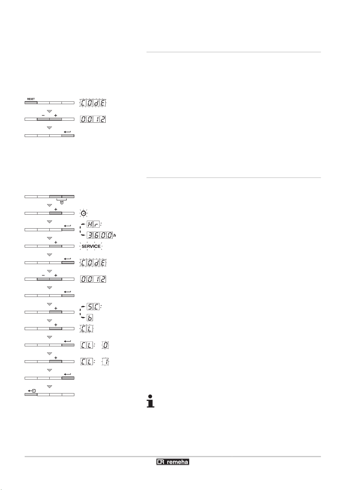
T001629-A
1x
T001630-A
3x
5x
...x
...x
7. Checking and maintenance Calenta 25s - 28c - 35s - 40c
7.2.1. Resetting the automatic maintenance
message
A service message on the boiler display must be reset by a qualified
installer after the maintenance service has been carried out using the
relevant service set and after this has been entered in the checklist
in the supplied service book. To do this, proceed as follows:
1. When the maintenance message is displayed, press key
time.
c0de
2. Use keys [-] or [+] to input the installer code
appears on the display.
0012
.
J
1
3. Confirm using key S. The maintenance message is reset. The
display returns to the current operating mode.
7.2.2. Dealing with the next maintenance
message and starting the new maintenance
period
For an interim service it is advisable to read out in the boiler service
menu what maintenance service should be carried out. Use the
indicated Remeha service sets (A, B or C). This service message
must be prevented by carrying out a reset. Start the next service
interval. To do this, proceed as follows:
1. Press the two keys f simultaneously and then key [+] until the
symbol \ flashes on the menu bar.
2. Press the S key.
operation
3600
3. Press key [+] several times until
4. Press the S key.
5. Use keys [-] or [+] to input the installer code
6. Confirm using key S.
7. Press key [+] several times until
example) flashing To determine the best time to carry out
maintenance, the boiler is fitted with a single automatic
maintenance indicator.
8. Press the [+] key a second time.
9. Press the S key.
10.Press key [+] to modify the value to 1.
and the number of hours of boiler
hr
(for example) are displayed alternately.
flashes on the menu bar.
K
c0de
cl[0
appears on the display.
0012
5c[B
cl
is displayed with B (for
appears on the display.
.
is displayed with 0 flashing.
11.Confirm using key S. The new maintenance period begins.
12.Press the
key 3 times to return to the current operating
>
mode.
After maintenance operations, fill in the corresponding
checklist in the maintenance log provided. Stick
maintenance sticker A, B or C from the maintenance kit
concerned in the maintenance log and inside the front
panel.
74
040412 - 7600585-01

Calenta 25s - 28c - 35s - 40c
7.3 Standard inspection and maintenance operations
CAUTION
During inspection and maintenance operations, always
replace all gaskets on the parts removed.
Before carrying out any work, check whether the boiler has
been adapted to one of the following situations:
4 G20 (Gas H) or G31 (Propane)
4 high pressure systems
4 WTW coupling
4 CLV overpressure (combusted gas discharge
systems)
See the sticker on top of the boiler next to the identification
plate.
7.3.1. Checking the hydraulic pressure
7. Checking and maintenance
The hydraulic pressure must reach a minimum of 0,8 bar. If the water
pressure is lower than 0,8 bar, the symbol e will appear.
If necessary, top up the water level in the heating system
(recommended hydraulic pressure between 1,5 and 2 bar).
7.3.2. Checking the ionization current
Check the ionization current at full load and low load. The value is
stable after 1 minute. If the value lies below 3 µA, replace the ignition
electrode.
¼ See chapter: "Reading the various current values", page 61.
7.3.3. Checking the transfer capacity
If the transfer capacity is noticably low (temperature too low and/or
flow rate less than 6,2 l/min), clean the plate exchanger (domestic hot
water side) and the water filter cartridge.
¼ See chapter: "Cleaning the plate exchanger (domestic hot
water end) and the water filter cartridge", page 79
040412 - 7600585-01
75

T001525-A
T001526-A
T001631-B
...x
7. Checking and maintenance
Calenta 25s - 28c - 35s - 40c
7.3.4. Checking the tightness of the flue gas
evacuation and air inlet connections
Check the tightness of the flue gases evacuation and air inlet
connections.
7.3.5. Checking combustion
The check on combustion is done by measuring the percentage of
O2/CO2 in the flue gas discharge flue. To do this, proceed as follows:
1. Unscrew the plug of the flue gas measurement point.
2. Connect the flue gas analyser.
CAUTION
Ensure that the opening around the sensor is completely
sealed when taking measurements.
3. Set the boiler to full load. Press the two B keys simultaneously.
The B symbol is visible on the menu bar and
appears in the
h3
display. The boiler is now operating at full load.
4. Measure the percentage of CO2 and compare this value with the
checking values given.
See chapter: "Setting the air/gas
¼
ratio (Full load)", page 57.
5. Set the boiler to part load. Press the [-] key several times until
is displayed on the screen. The boiler is now operating on
l3
part load.
6. Measure the percentage of CO2 and compare this value with the
checking values given.
See chapter: "Setting the air/gas
¼
ratio (Part load)", page 59.
76
040412 - 7600585-01

R000074-B
6
5
5
5
4
90º
4
1
Gas/Gaz
2 3
Calenta 25s - 28c - 35s - 40c
7. Checking and maintenance
7.3.6. Checking the automatic air vent
1. Cut the power supply to the boiler.
2. Close the gas valve on the boiler.
3. Close the main gas inlet valve.
4. Unscrew the two screws located under the front panel by a quarter
turn and remove the panel.
5. Tilt the control box forwards by opening the holding clips located
at the sides.
6. Check whether there is any water in the small hose on the
automatic air vent.
7. If any leaks are detected, replace the air vent.
7.3.7. Checking the safety valve
1. Take out the flow collector located under the boiler.
2. Check whether there is any water in the end of the flow pipe on
the safety valve.
3. If any leaks are detected, replace the safety valve.
7.3.8. Checking the siphon
1. Remove the siphon and clean it.
2. Fill the siphon with water.
3. Put the siphon back in place.
040412 - 7600585-01
77

T001220-B
2
X91
1
10
11
3
5
4
4
12
7
8
9
6
7. Checking and maintenance Calenta 25s - 28c - 35s - 40c
7.3.9. Checking the burner and cleaning the heat
exchanger
CAUTION
During inspection and maintenance operations, always
replace all gaskets on the parts removed.
1. Remove the air inlet flue on the venturi.
2. Unscrew the top connection on the gas valve unit.
3. Disconnect the connector located under the fan.
4. Release the 2 clips holding the fan/mixing elbow unit in place on
the heat exchanger.
5. Completely remove the fan/mixing elbow unit.
6. Tilt the burner and remove it, along with the heat exchanger
gasket.
7. Use a vacuum cleaner fitted with a special endpiece (accessory)
to clean the top part of the heat exchanger (combustion chamber).
8. Thoroughly clean with the vacuum cleaner again without the top
cleaning brush on the endpiece.
9. Check (using a mirror, for example) whether any dust can still be
seen. If so, hoover it up.
10.The burner does not require any maintenance, it is self-cleaning.
Check that there are no cracks and/or other tears on the surface
of the dismantled burner. If this is not the case, replace the burner.
11.Checking the ignition electrode / ionization sensor.
12.To re-assemble, perform the above actions in reverse order.
13.Open the gas inlet valves and reconnect the plug to the mains.
CAUTION
4 Remember to reconnect the connector to the fan.
4 Check that the gasket is correctly positioned between
the mixing elbow and the heat exchanger.
(Completely flat in the appropriate groove means it is
leak proof).
78
040412 - 7600585-01

T001528-A
1
2
3
Calenta 25s - 28c - 35s - 40c
7.4 Specific maintenance operations
If the standard inspection and maintenance operations have revealed
the necessity to carry out additional maintenance work, proceed as
follows, depending on the nature of the work:
7.4.1. Replacing the ionization/ignition electrode
Replace the ionization/ignition electrode in the following cases:
4 Ionization current <3 µA.
4 Electrode worn.
4 Electrode available in the maintenance kit.
7. Checking and maintenance
CAUTION
After maintenance operations, fill in the corresponding
checklist in the maintenance log provided .
If replacement is necessary, proceed as follows:
1. Remove the cable from the ionization/ignition electrode on the
ignition transformer.
2. Unscrew the 2 screws and remove the ionization/ignition
electrode.
3. Replace the ionization/ignition electrode.
7.4.2. Cleaning the plate exchanger (domestic hot
water end) and the water filter cartridge
Depending on the water quality and the operating mode, limescale
deposits may form in the plate exchanger and the water filter
cartridge. Periodic descaling may therefore be necessary. As a
general rule, a periodic inspection, along with cleaning, if necessary,
is sufficient. The following factors may affect the periodicity:
4 Water hardness.
4 Composition of the limescale.
4 Number of hours' operation of the boiler.
4 Draw-off rate.
4 Domestic hot water set point temperature.
040412 - 7600585-01
79

T001622-C
3
4
5
6
7
7
3
2
1
8
H2O
21
+/+ H2O
7. Checking and maintenance Calenta 25s - 28c - 35s - 40c
Cleaning the plate exchanger
n
If descaling of the plate exchanger is necessary, proceed as follows:
1. Close the main water valve.
2. Drain the boiler.
3. Remove the air vent hose above the siphon.
4. Remove the siphon.
5. Remove the clip holding the heating flow hose in place on the left
side of the hydroblock.
6. Dismantle the heating flow hose on the left side of the hydroblock
and not on the heat exchanger side (heating circuit).
7. Unscrew the 2 hexagonal socket screws located to the right and
left of the plate exchanger.
8. Slightly turn the plate exchanger and carefully remove it from the
boiler.
9. Clean the plate exchanger with a descaling product (e.g. citric acid
with a pH of approximately 3). To do this, a specific cleaning
appliance is available as an accessory. After cleaning, rinse
thoroughly under running water.
10.Re-assemble all of the components.
80
040412 - 7600585-01

T001624-B
+/+ pH 3
+/+ H2O
3
4
5
6
7 8
H2O
21
Calenta 25s - 28c - 35s - 40c 7. Checking and maintenance
Cleaning the domestic water cartridge
n
If cleaning or replacement of the water filter cartridge is necessary,
proceed as follows:
1. Close the main water valve.
2. Drain the boiler.
3. Remove the air vent hose above the siphon.
4. Remove the siphon.
5. Remove the clip holding the water filter cartridge in place. While
doing this, be sure that the silencer is left in place.
6. Remove the domestic water cartridge.
7. Rinse the water filter cartridge with tap water and, if need be, clean
it with a descaling product (e.g. citric acid with a pH of
approximately 3). After cleaning, rinse thoroughly under running
water.
8. Replace the water filter cartridge if faulty or when the maintenance
kit includes one.
9. Re-assemble all of the components.
040412 - 7600585-01
81

T002639-C
3
4
5
6
21
7
8
9
1
2
10
1 2
7. Checking and maintenance Calenta 25s - 28c - 35s - 40c
7.4.3. Replacing the 3-way valve
If it becomes necessary to replace the 3-way valve, proceed as
follows:
1. Close the main water valve
2. Drain the boiler.
3. Remove the air vent hose above the siphon.
4. Remove the siphon.
5. Remove the clip holding the heating return hose in place on the
right side of the hydroblock.
6. Remove the heating return hose on the right side of the hydroblock
and not on the heat exchanger side (heating circuit).
7. Unplug the actuator.
8. Remove the clip holding the 3-way valve in place.
9. Remove the 3-way valve.
Lift and rotate by a quarter turn.
10.Proceed as for dismantling in reverse.
CAUTION
Be careful of the positioning cams on the 3-way valve.
82
040412 - 7600585-01

T002517-B
2x
6
2
X91
3
1
4
2x
5
Calenta 25s - 28c - 35s - 40c 7. Checking and maintenance
7.4.4. Replacing the non-return valve
Replace the nonreturn valve when faulty or when the maintenance kit
contains one. To do this, proceed as follows:
1. Remove the air inlet flue on the venturi.
2. Unscrew the top connection on the gas valve unit.
3. Disconnect the connector located under the fan.
4. Release the 2 clips holding the fan/mixing elbow unit in place on
the heat exchanger.
5. Completely remove the fan/mixing elbow unit.
6. Replace the non-return valve located between the mixing elbow
and the fan.
7. To re-assemble, perform the above actions in reverse order.
040412 - 7600585-01
83

T001529-B
7. Checking and maintenance Calenta 25s - 28c - 35s - 40c
7.4.5. Assembling the boiler
1. Follow the procedure in reverse to re-assemble all of the
components.
CAUTION
During inspection and maintenance operations, always
replace all gaskets on the parts removed.
2. Fill the siphon with clean water up to the mark.
3. Put the siphon back in place.
CAUTION
Mount the vent hose above the siphon.
4. Carefully open the main water valve, fill the installation, vent it and,
if need be, top it up with water.
5. Check the seals on the gas and water connections.
6. Switch the boiler back on.
After maintenance operations, fill in the corresponding
checklist in the maintenance log provided.
84
040412 - 7600585-01

Calenta 25s - 28c - 35s - 40c 8. Troubleshooting
8 Troubleshooting
8.1 Error codes
The boiler is fitted with an electronic regulation and control unit. The
heart of the control system is a microprocessor, the Comfort
Master©, which controls the boiler and also protects the boiler. If a
fault is detected anywhere in the boiler, the boiler locks out and the
display will show the fault code as follows:
In a red flashing display:
4 The symbol c
4 The symbol J
4 The fault code (for example e[01)
The meaning of the error codes is given in the error table. To do this,
proceed as follows:
Error
code
e[00
e[01
e[02
e[03
4 Note the error code displayed.
The error code is important for rapid and correct tracking
of the type of problem and for any technical assistance from
Remeha.
4 Press the J key for 2 seconds. If the error code continues to
display, search for the cause in the error table and apply the
solution.
If the display does not show J but rather a, the boiler
must be switched off and then switched on again after 10
seconds before the fault can be reset.
Description Probable causes Checking / solution
Storage unit PSU
parameter not found
The safety parameters
are incorrect
Flow temperature sensor
short circuited
Flow temperature sensor
open circuit
4 Bad connection 4 Check the wiring
4 Bad connection
4 PSU defective
4 Bad connection
4 Sensor fault
4 Sensor not or badly
connected
4 Bad connection
4 Sensor fault
4 Sensor not or badly
connected
4 Check the wiring
4 Replace PSU
4 Check the wiring
4 Check that the sensors are operating correctly
4 Check that the sensor has been correctly fitted
4 Replace the sensor if necessary
4 Check the wiring
4 Check that the sensors are operating correctly
4 Check that the sensor has been correctly fitted
4 Replace the sensor if necessary
040412 - 7600585-01
85

8. Troubleshooting Calenta 25s - 28c - 35s - 40c
Error
code
e[04
e[05
e[06
e[07
e[08
e[09
e[10
e[11
e[12
Description Probable causes Checking / solution
4 Check the wiring
4 Replace the sensor if necessary
Temperature of heat
exchanger too low
Exchanger temperature
too high
4 Bad connection
4 Sensor fault
4 Sensor not or badly
connected
4 No circulation
4 Vent the air in the heating system
4 Check the circulation (direction, pump, valves)
4 Check the water pressure
4 Check that the sensors are operating correctly
4 Check that the sensor has been correctly fitted
4 Check the cleanliness of the heat exchanger
Return temperature
sensor short circuited
Return temperature
sensor open circuit
4 Bad connection
4 Sensor fault
4 Sensor not or badly
connected
4 Bad connection
4 Sensor fault
4 Sensor not or badly
connected
4 Check the wiring
4 Check that the sensor has been correctly fitted
4 Check that the sensors are operating correctly
4 Check the wiring
4 Check that the sensor has been correctly fitted
4 Check that the sensors are operating correctly
4 Check the wiring
4 Replace the sensor if necessary
Return temperature too
low
Return temperature too
high
4 Bad connection
4 Sensor fault
4 Sensor not or badly
connected
4 No circulation
4 Vent the air in the heating system
4 Check the circulation (direction, pump, valves)
4 Check the water pressure
4 Check that the sensors are operating correctly
4 Check that the sensor has been correctly fitted
4 Check the cleanliness of the heat exchanger
4 Replace the sensor if necessary
4 Vent the air in the heating system
Difference between the
flow and return
temperatures too great
4 Sensor fault
4 Sensor not or badly
connected
4 No circulation
4 Check the circulation (direction, pump, valves)
4 Check the water pressure
4 Check that the sensors are operating correctly
4 Check that the sensor has been correctly fitted
4 Check the cleanliness of the heat exchanger
4 Check that the heating pump is operating correctly
4 Check the wiring
4 Replace the sensor if necessary
Temperature of heat
exchanger above normal
range (high-limit
thermostat STB)
4 Bad connection
4 Sensor fault
4 Sensor not or badly
connected
4 No circulation
4 Vent the air in the heating system
4 Check the circulation (direction, pump, valves)
4 Check the water pressure
4 Check that the sensors are operating correctly
4 Check that the sensor has been correctly fitted
4 Check the cleanliness of the heat exchanger
86
040412 - 7600585-01

Calenta 25s - 28c - 35s - 40c 8. Troubleshooting
Error
code
e[14
e[16
e[17
e[34
e[35
e[36
e[37
Description Probable causes Checking / solution
4 Check cabling of ignition transformer
4 Check the ionization/ignition electrode
4 No ignition
4 Check breakdown to earth
4 Check the condition of the burner set
4 Check the earthing
4 Defective control SU PCB
4 Purge the gas supply to remove air
4 Check that the gas valve is fully opened
4 Check the supply pressure
5 burner start-up failures
4 Ignition arc, but no flame
formation
4 Check the operation and setting of the gas valve unit
4 Check that the air inlet and flue gas discharge flues
are not blocked
4 Check the wiring on the gas valve unit
4 Defective control SU PCB
4 Check that the gas valve is fully opened
4 Presence of the flame
but insufficient ionization
(<3 µA)
4 Check the supply pressure
4 Check the ionization/ignition electrode
4 Check the earthing
4 Check the wiring on the ionization/ignition electrode
4 Ionization current
present when there
False flame signal
should not be a flame
4 Ignition transformer
defective
4 Gas valve defective
4 Check the ionization/ignition electrode
4 Check the gas valve and replace if necessary
4 Set the CO
2
4 The burner remains very
hot: CO2 too high
Problem on the gas
valve SU PCB
Fan fault
4 Bad connection
4 Defective SU PCB
4 Bad connection
4 Fan defective
4 Check the wiring
4 Inspect the SU PCB and replace it if need be
4 Check the wiring
4 Replace the fan if need be
4 Check for adequate draw on the chimney connection
4 Bad connection
4 Replace the sensor if necessary
4 Check the circulation (direction, pump, valves)
4 Check that the sensors are operating correctly
4 Check that the sensor has been correctly fitted
Flow and return reversed
4 Sensor fault
4 Sensor not or badly
connected
4 Water circulation
direction reversed
4 Purge the gas supply to remove air
4 Check that the gas valve is fully opened
4 Check the supply pressure
5x Flame loss
4 No ionization current
4 Check the operation and setting of the gas valve unit
4 Check that the air inlet and flue gas discharge flues
are not blocked
4 Check that there is no recirculation of flue gases
Communication error
with the SU PCB
4 Bad connection
4 Check whether the SU PCB has been correctly fitted
in the connector on PCU PCB
040412 - 7600585-01
87

T001632-B
8. Troubleshooting Calenta 25s - 28c - 35s - 40c
Error
code
e[38
e[39
e[40
Description Probable causes Checking / solution
Communication error
with the SCU PCB
Shutdown input in
locked-out mode
HRU/URC unit test error
4 Bad connection
4 Defective SCU PCB
4 Bad connection
4 External cause
4 Parameter incorrectly
set
4 Bad connection
4 External cause
4 Parameter incorrectly
set
8.2 Shutdowns and lock-outs
4 Check the wiring
4 Replace SCU PCB
4 Check the wiring
4 Suppress the external cause
4 Check the parameters
4 Check the wiring
4 Suppress the external cause
4 Check the parameters
8.2.1. Blockage
If the blocking conditions still exist after several start up attempts, the
boiler will switch into locking mode (fault). The boiler can only start
operating again once the causes of the lock-out have been rectified
and after pressing the > key.
8.2.2. Blocking
A (temporary) blocking mode is a boiler operating function caused by
an unusual situation. In this case, the display gives a code of blocking
(code 5t[9). The boiler control will try to re-start several times.
The boiler will start up again after the blocking conditions have been
eliminated. The shutdown codes can be read out as follows:
1. Press the two f keys simultaneously.
2. Confirm by pressing key S.
the shutdown code 9.
3. Press the [+] key.
appears on the display.
5v
is displayed, alternating with
5t
88
040412 - 7600585-01

Calenta 25s - 28c - 35s - 40c 8. Troubleshooting
The boiler starts up again automatically when the reason
for the blocking has been removed.
Shutdown
Description Probable causes Checking / solution
code
5v[0
5v[1
5v[2
5v[7
Parameter error
Maximum flow temperature
exceeded
Maximum increase of the
flow temperature has been
exceeded
Maximum difference
between the flow and return
temperature exceeded
4 Parameter error on the
4 Non-existent or
4 Non-existent or
4 Sensor error
4 Non-existent or
4 Sensor error
4 External cause
5v[8
No release signal
4 Parameter error
4 Bad connection
4 Mains supply incorrectly
5v[9
Phase and neutral of mains
supply mixed up
4 Floating or 2 phase
4 External cause
5v[10
Shutdown input is open
4 Parameter error
4 Bad connection
4 External cause
5v[11
Shutdown input active or frost
protection active
4 Parameter error
4 Bad connection
4 Bad connection with BUS
4 SCU PCB not installed in
4 Water pressure too low
5v[13
5v[14
Communication error with the
SCU PCB
Water pressure too low
4 Non-existent or
5v[15
5v[16
5v[17
(1) These lock-outs are not stored in the fault memory
Gas pressure too low
Configuration fault or SU
(1)
PCB not recognised
Configuration fault or default
(1)
parameter table incorrect
4 Incorrect setting of the
4 Wrong SU PCB for this
4 Parameter error on the
PSU PCB
insufficient circulation
insufficient circulation
insufficient circulation
wired
network
the boiler
insufficient circulation
Gps gas pressure switch
on the SCU PCB
boiler
PCU PCB
4 Reset df and dV
4 Restore parameters with Recom
4 Check the circulation (direction, pump,
valves)
4 Reasons for the heat demand
4 Check the circulation (direction, pump,
valves)
4 Check the water pressure
4 Check that the sensors are operating
correctly
4 Check that the sensor has been correctly
fitted
4 Check the cleanliness of the heat exchanger
4 Check the circulation (direction, pump,
valves)
4 Check the water pressure
4 Check that the sensors are operating
correctly
4 Check that the sensor has been correctly
fitted
4 Check the cleanliness of the heat exchanger
4 Suppress the external cause
4 Check the parameters
4 Check the wiring
4 Invert phase and neutral
4 Set parameter p43 to 0
4 Suppress the external cause
4 Check the parameters
4 Check the wiring
4 Suppress the external cause
4 Check the parameters
4 Check the wiring
4 Check the wiring
4 Carry out automatic detection
4 Check the water pressure
4 Fill the boiler and the installation with water
4 Check that the gas valve is fully opened
4 Check the supply pressure
4 Check whether the Gps gas pressure control
system has been correctly fitted
4 Replace the Gps gas pressure control
system if need be
4 Replace the SU PCB
4 Replace the PCU PCB
040412 - 7600585-01
89
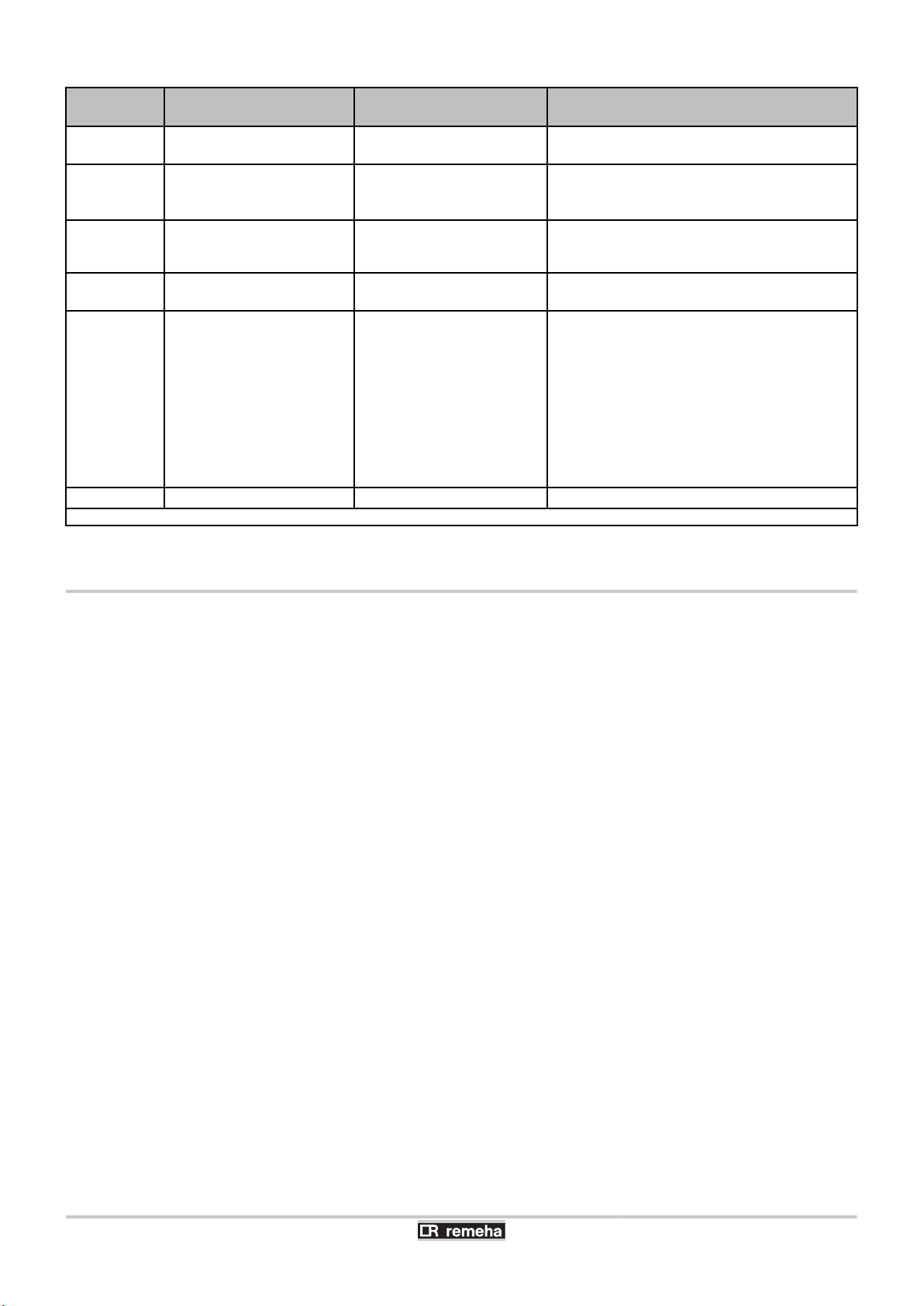
8. Troubleshooting Calenta 25s - 28c - 35s - 40c
Shutdown
code
5v[18
5v[19
5v[20
5v[21
5v[22
5v[25
(1) These lock-outs are not stored in the fault memory
Description Probable causes Checking / solution
Configuration fault or PSU
(1)
PCB not recognised
Configuration fault or
(1)
parameters df-dV
unknown
Configuration procedure
(1)
active
Communication error with the
SU PCB
No flame during operation
Internal error on the SU PCB
4 Wrong PCU PCB for this
4 Active for a short time
4 Bad connection
4 No ionization current
boiler
after switching on the
boiler
4 Replace the PCU PCB
4 Reset df and dV
4 No action required
4 Check whether the PCU PCB has been
correctly fitted in the connector on SU PCB
4 Purge the gas supply to remove air
4 Check that the gas valve is fully opened
4 Check the supply pressure
4 Check the operation and setting of the gas
valve unit
4 Check that the air inlet and flue gas discharge
flues are not blocked
4 Check that there is no recirculation of flue
gases
4 Replace the SU PCB
8.3 Error memory
The boiler control is equipped with an error memory. The last 16 errors
encountered are recorded in this memory.
In addition to the error codes, the following data are also saved:
4 Number of times that the error occured: (MK[xx).
4 Boiler operating mode selected (5t[xx).
4 The flow temperature (t1[xx) and the return temperature
(t2[xx) when the error occured.
To view the error memory, you first have to enter access code
0012.
90
040412 - 7600585-01

T001530-B
4x
2x
Calenta 25s - 28c - 35s - 40c
8. Troubleshooting
8.3.1. Error readout memorised
1. Press the two keys f simultaneously and then key [+] until the
symbol c flashes on the menu bar.
2. Select the installers menu using the key S.
c0de
on the display.
3. Use keys [-] or [+] to input the installer code
4. Press the S key.
er[xx
appears on the display.
0012
5. The fault list or shutdown list can be displayed by pressing the
[-] or [+] key..
6. Confirm using key S.
er[xx
is displayed with
flashing = Last error which occured, For example
7. Use the [-] or [+] key to scroll through the faults or shutdowns.
8. Press the S key to display the details of the faults or shutdowns.
9. Press the [-] or [+] key to view the following information:
= Number of times that the error occured.
M[1
= The number of operating hours.
hr
= State.
5t
= Sub-status.
5v
= Supply temperature ºF/ºC.
t1
= Return temperature ºF/ºC.
t"
= Calorifier temperature ºF/ºC.
t3
= Outside temperature ºF/ºC (Only with an outside
t4
temperature sensor).
= Solar boiler temperature ºF/ºC.
t5
= Internal set point ºF/ºC.
5p
= Ionization current (µA).
fl
= Fan speed in rpm.
Mf
= Water pressure psig/bar.
pr
= Supplied relative heat output (%).
p;
10.Press the
displayed with
key to interrupt the display cycle.
>
flashing = Last error which occured.
xx
11.Use the [-] or [+] key to scroll through the faults or shutdowns.
12.Press the
13.Press
>
key to show the fault list or shutdown list.
>
times on the key 2 to exit the error memory.
appears
.
xx
.
K2
er[xx
is
040412 - 7600585-01
91

T000831-D
3x
4x
8. Troubleshooting Calenta 25s - 28c - 35s - 40c
8.3.2. Deletion of the error display
1. Press the two keys f simultaneously and then key [+] until the
symbol c flashes on the menu bar.
2. Select the installers menu using the key S.
c0de
on the display.
3. Use keys [-] or [+] to input the installer code
4. Press the S key.
er[xx
appears on the display.
0012
5. The fault list or shutdown list can be displayed by pressing the
[-] or [+] key..
6. Confirm using key S.
er[xx
7. Press the [+] key several times until
is displayed with
er[cl
is displayed on the
screen.
8. Press the S key.
cl[0
is displayed with 0 flashing.
9. Press key [+] to modify the value to 1.
10.Press the S key to delete the errors from the error memory.
11.Press
times on the key 3 to exit the error memory.
>
xx
appears
.
flashing.
92
040412 - 7600585-01

Calenta 25s - 28c - 35s - 40c
9 Spare parts
9.1 General
9. Spare parts
When it is observed subsequent to inspection or maintenance work
that a component in the boiler needs to be replaced, use only original
spare parts or recommended spare parts and equipment.
Send the component to be replaced to the Returned Goods
Department at Remeha when the corresponding part falls under the
warranty terms (see the general terms and conditions of sale and
supply).
Always ensure that your return package is accompanied
by the duly completed return form, see attached
example. In this way, Remeha can more easily and more
effectively expedite its warranty obligations.
Customer
Reference
Name
Address
Town/Postcode
Telephone
Contact person
Order number
Code no. Description
(1) This information can be found on the rating plate.
Serial number
(1)
Date
Type Installation date Reason for the exchange Reference
9.2 Spare parts
040412 - 7600585-01
93

T000428-C
2025
2028
2026
2027
2028
2024
2022
2023
2006
2002
2034
2034
2013
2014
2012
2011
2011
4016
2015
2033
2015
2005
2005
2032
2010
2007
2004
2003
2009
2030
2030
2032
2010
2020
2021
2016
2001
2018
2017
2019
2029
2022
1004
1001
1002
1006
1003
3004
3002
3011
3012
3008
3001
3008
3006
3010
3005
3003
3007
4011
4010
4014
4012
4013
4009
4004
4001
4014
4003
5010
4009
5009
4002
5037
5017
5014
5015
5008
5020
5017
5003
5023
5022
5022
5018
5021
5002
5016
5019
5017
5017
5007
5017
5029
5006
5018
5031
5031
5030
5029
5027
5028
5004
5017
5001
5029
5029
5032
5032
5016
5017
9. Spare parts Calenta 25s - 28c - 35s - 40c
Calenta 25s, 28c
94
040412 - 7600585-01

T002883-A
1003
3005
3003
2016
2011
4008
2033
4007
2032
5012
4001
4014
4004
4003
5019
5017
5017
5016(2X)
5004
4013
5029
5029
5030
5027
5028
5055
5006
5020
5018
5007
5016
4009
4014
5001
2004
2025
2029
2028
2025
2022
2024
2019
2018
2013
2014
2015
2034
2003
5014
5017
5008
5015
2030
5025
2030
2009
5011
2007
20154015 /
2032
5012
2012
2017
2001
2021
2020
2002
2006
4009
5017
5018
5029
5032
5002
5031
4010
4011
4012
4002
2022
2010
5013
5017
5017
5029
5017
5032
5031
5029
3002
3012
3001
3008
3006
3010
3004
3011
3008
2005
2005
2010
5013
2027
1001
1004
4005
5009
5023
2023
4006
5010
5023
5003
5022
5004
5021
5022
2011
4008
2050
4016
2034
1002
1006
3007
EV 119377-1/5
Calenta 25s - 28c - 35s - 40c 9. Spare parts
Calenta 35s, 40c
040412 - 7600585-01
95

9. Spare parts Calenta 25s - 28c - 35s - 40c
96
040412 - 7600585-01


Remeha B.V.
Postbus 32
7300 AA Apeldoorn
Tel: +31 55 5496969
Fax: +31 55 5496496
Internet: http://nl.remeha.com
E-mail: remeha@remeha.com
NL
© Copyright
T001778-C
NZ
T001800-B
NZ
7600585
All technical and technological information contained in these technical instructions,
as well as any drawings and technical descriptions supplied, remain our property
and shall not be multiplied without our prior consent in writing.
040412
 Loading...